EP0337235B1 - Schutzrelais-Prüfanordnung für die Verwendung während des Betriebs des Relais - Google Patents
Schutzrelais-Prüfanordnung für die Verwendung während des Betriebs des Relais Download PDFInfo
- Publication number
- EP0337235B1 EP0337235B1 EP19890105808 EP89105808A EP0337235B1 EP 0337235 B1 EP0337235 B1 EP 0337235B1 EP 19890105808 EP19890105808 EP 19890105808 EP 89105808 A EP89105808 A EP 89105808A EP 0337235 B1 EP0337235 B1 EP 0337235B1
- Authority
- EP
- European Patent Office
- Prior art keywords
- circuit
- relay
- coil
- injector
- test
- Prior art date
- Legal status (The legal status is an assumption and is not a legal conclusion. Google has not performed a legal analysis and makes no representation as to the accuracy of the status listed.)
- Expired - Lifetime
Links
- 238000012360 testing method Methods 0.000 title claims description 51
- 230000011664 signaling Effects 0.000 claims description 11
- 238000009434 installation Methods 0.000 claims description 10
- 230000005284 excitation Effects 0.000 claims description 3
- 238000010616 electrical installation Methods 0.000 claims description 2
- 230000003247 decreasing effect Effects 0.000 claims 1
- 238000002347 injection Methods 0.000 description 55
- 239000007924 injection Substances 0.000 description 55
- 230000006870 function Effects 0.000 description 4
- 230000001629 suppression Effects 0.000 description 4
- 238000012795 verification Methods 0.000 description 4
- 238000010586 diagram Methods 0.000 description 3
- 230000015654 memory Effects 0.000 description 3
- 239000004973 liquid crystal related substance Substances 0.000 description 2
- 238000012544 monitoring process Methods 0.000 description 2
- 241000282472 Canis lupus familiaris Species 0.000 description 1
- 230000009849 deactivation Effects 0.000 description 1
- 230000003111 delayed effect Effects 0.000 description 1
- 238000001514 detection method Methods 0.000 description 1
- 230000008030 elimination Effects 0.000 description 1
- 238000003379 elimination reaction Methods 0.000 description 1
- 238000012423 maintenance Methods 0.000 description 1
- 230000014759 maintenance of location Effects 0.000 description 1
- 239000000203 mixture Substances 0.000 description 1
- 230000001681 protective effect Effects 0.000 description 1
- 230000004044 response Effects 0.000 description 1
- 230000000284 resting effect Effects 0.000 description 1
- 230000000717 retained effect Effects 0.000 description 1
- 238000012163 sequencing technique Methods 0.000 description 1
- 238000010200 validation analysis Methods 0.000 description 1
Images


Classifications
-
- G—PHYSICS
- G01—MEASURING; TESTING
- G01R—MEASURING ELECTRIC VARIABLES; MEASURING MAGNETIC VARIABLES
- G01R31/00—Arrangements for testing electric properties; Arrangements for locating electric faults; Arrangements for electrical testing characterised by what is being tested not provided for elsewhere
- G01R31/327—Testing of circuit interrupters, switches or circuit-breakers
- G01R31/3277—Testing of circuit interrupters, switches or circuit-breakers of low voltage devices, e.g. domestic or industrial devices, such as motor protections, relays, rotation switches
- G01R31/3278—Testing of circuit interrupters, switches or circuit-breakers of low voltage devices, e.g. domestic or industrial devices, such as motor protections, relays, rotation switches of relays, solenoids or reed switches
Definitions
- the invention relates to a device for testing a set of electrical protection relays of an installation during its operation.
- An object of the invention is to provide a device for testing a set of protection relays without interrupting the operation of the installation.
- Another object of the invention is to provide a test device allowing an automatic test of the various relays and according to a predetermined sequence.
- the relays are tested individually and successively in a predetermined sequence.
- the test is of the type giving the result: GOOD - not GOOD.
- the circuit of use of the relay tested is open to avoid any untimely tripping.
- a relay work contact is reserved for signaling the test result.
- the invention relates to a device for testing protective relays of an electrical installation without interrupting its operation, each of the relays comprising at least one coil controlling contacts, a number of which is connected to a use circuit comprising in particular a circuit breaker and / or a signaling device, and another of which is inserted in a signaling circuit signaling the operation or non-operation of said protection relay ,
- this device comprising a sequencer circuit comprising an automaton programmed to establish a predetermined test sequence, an injection circuit comprising means for developing currents of calibrated values and voltages of given value, and injection boxes each of which is associated with one of the protection relays tested and includes an injection relay comprising a coil supplied via said sequencer circuit and actuating contacts making it possible to switch and inject a calibrated test current or a voltage of test, supplied by the injection circuit, and this device being essentially characterized in that ch none of said injection boxes comprises a locking relay comprising a coil and contacts in series with the circuit of use of the corresponding tested protection relay, in that said calibr
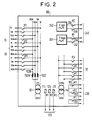
- the example chosen to illustrate the invention shows three protection relays 10, 20 and 30.
- the invention normally applies to the monitoring of an assembly which may include a much larger number of relays, of a few tens some hundreds.
- Relay 10 is a two-phase ammeter relay; the two coils of the relay, 11 and 12, are shown (phases ⁇ 1 and ⁇ 2) connected respectively to the secondary of current transformers 41 and 42 whose primaries 43 and 44 are traversed by the two phases of the current of the protected installation.
- the coils 11 and 12 actuate a contractor having contacts 13, 14 placed in series in a circuit of use comprising of course a cut-off member, but also various signaling members, not shown but generally designated by the letters ut10.
- the contactor has another contact 15, which is used to signal the result of the test to a sequencing circuit 120 whose role and operation will be described later.
- the second relay 20 is another single-phase ammeter relay, comprising a coil 21 connected to the current transformer 41.
- the coil 21 actuates contacts 23 and 24 in series in the use circuit ut20 of the relay and a contact 25 connected to the sequencer circuit 120 to signal the result of the test.
- the third relay 30 is a voltage relay protecting for example the first phase ⁇ 1 from use and which comprises a coil 31, supplied by the secondary of a potential transformer 50, the primary of which receives the voltage U from the installation to monitor.
- the coil 31 actuates a contactor having two contacts 33 and 34 for use ut30 and a contact 35 used by the sequencer circuit 120 to indicate the result of the test.
- the relay test is, as already indicated, carried out by injecting a suitable current or voltage into the relay coil and then disconnecting the output contacts from use.
- Each of the relays is associated with an injection box which performs these functions.
- the injection boxes associated with relays 10, 20 and 30 have been designated by 60, 70 and 80 respectively.
- the injection box 60 comprises an injection relay having a coil 61 actuating two pairs of injection contacts 62, 63, 64 and 68, in series with the coils 11 and 12 and traversed by currents of given value supplied by an injection circuit 100 which will be described in detail below.
- the coil 61 is supplied by the sequencer circuit 120.
- the injection box 60 further comprises a second relay, called a locking relay, having a coil 65 which actuates contacts 66 and 67 in series in the use circuit ut10 of the relay 10 to be tested.
- a second relay called a locking relay
- the contacts 66 and 67 are normally closed and only open when the coil 65 is energized.
- the injection box 70 comprises, in the same way, an injection relay having a coil 71 actuating contacts 72 and 73 in series with the coil 21 and supplied by the injection circuit 100; the injection box has a locking relay having a coil 75 actuating contacts 76 and 77 in series with the use circuit ut20 of the relay 20.
- the injection box 80 associated with the voltage relay 30 contains two resistors 91 and 92, in series in the transformer circuit 50, and whose value is chosen so that only the injected voltage operates the relay during the test .
- the resistances are for example of the order of 1000 ohms.
- the injection box 80 comprises, like the other boxes, an injection relay having a coil 81 controlling two contacts 82 and 83 arranged in series with the coil 31 of the relay to be tested and connected to the injection circuit 100; the box also includes a locking relay having a coil 85 actuating contacts 86 and 87 in series in the use circuit ut30 of the relay 30.
- the coils 81 and 85 are supplied by the sequencer circuit 120.
- the injection circuit is very partially represented since only the supply wires of the phases used ( ⁇ 1, ⁇ 2) and of the size used have been shown.
- the injection circuit comprises a current generator comprising a potential transformer 101 (for example 220 V alternating at the primary and 12 V alternating at the secondary) whose secondary circuit is in series with a resistor 102 providing a current of given intensity.
- a potential transformer 101 for example 220 V alternating at the primary and 12 V alternating at the secondary
- This current is distributed over one of the two phases ⁇ 1 and ⁇ 2 by means of two relays, one having a coil 111 actuating two contacts 112 and 113 (phase ⁇ 1), the other a coil 121 actuating two contacts 122 and 123 ( phase ⁇ 2).
- the coils 111 and 121 are supplied by the sequencer circuit 120.
- the injection circuit 100 further comprises, for the injection of test voltages, a potential transformer whose secondary is provided with contacts 142 and 143 actuated by the coil 111, to distribute the test voltage on phase ⁇ 1.
- the sequencer 120 is a programmable logic controller. It includes, on its front face, a liquid crystal display 150 and a number of push buttons such as 151, 152 and 153.
- the sequencer circuit sends control commands to the coils 111, 121 of the injection circuit relays for the choice of the injection phase as well as to the coils 61, 65, 71, 75 , 81, 85 of the injection and locking relays.
- the current injection by the transformer 101 allows, thanks to several secondary resistors 102A, 102B, 102C, several current ratings (for example 3 amps, 10 amps, 30 amps) which are distributed over the 3 phases by the coil relays 111, 121, 131.
- the relay 111, 121, 131 can also control a set of contacts 151, 152, 153 for short-circuiting the coils of a relay 230, not shown, at undervoltage.
- the injection circuit can also include voltage niche generators, such as generator 241 generating a voltage niche more or less 24 volts at a frequency fn + 10 Hz (fn: frequency of the supply circuit of the installation) and the generator 242 generating slots of frequency fn - 10Hz.
- voltage niche generators such as generator 241 generating a voltage niche more or less 24 volts at a frequency fn + 10 Hz (fn: frequency of the supply circuit of the installation) and the generator 242 generating slots of frequency fn - 10Hz.
- These generators supply one ( ⁇ 1) or the other ( ⁇ 2) of the phases of a frequency relay 240 not shown, by means of contactors 243, 244, 245, 246 controlled by the coils 111 and 121.
- Figure 3 shows how security is ensured in the injection box to prevent the injection voltage from being injected if the locking of the use disconnection relay is not ensured.
- the injection relay 81 is supplied in parallel with the locking relay 85.
- a contact 88, controlled by the locking relay 85 is in series with the coil 81.
- a diode 95 is connected to the supply circuit of the coil 85, and a diode 96 is in parallel on the coils 81 and 85.
- the operation is as follows: to carry out a test of the relay 31 by injecting a test voltage supplied by the injection circuit, the latching relay 85 is energized (by the sequencer 120); the coil 85 then closes the contacts 86 and 87, which disconnects the use circuit ut30 from the relay 31, as well as the contact 88.
- Relay 81 is then energized, which closes contacts 82 and 83 and allows injection of the test voltage.
- the coil V is supplied by the circuit 81, 85, 96 which ensures the maintenance of the locking and the deactivation of the use ut30.
- the latching relay is delayed when the excitation disappears (time greater than one second).
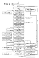
- sequencer 120 is an automaton comprising read-only memories in which the different types of tests to be performed are defined.
Landscapes
- Physics & Mathematics (AREA)
- General Physics & Mathematics (AREA)
- Testing Electric Properties And Detecting Electric Faults (AREA)
- Emergency Protection Circuit Devices (AREA)
Claims (3)
- Prüfvorrichtung für Schutzrelais (10, 20, 30) einer elektrischen Anlage, wobei die Prüfung ohne Betriebsunterbrechung der Anlage erfolgt und jedes Relais mindestens eine Spule (11, 12) und von ihr gesteuerte Kontakte (13, 14, 15) enthält, von denen einige (13, 14) mit einem Nutzkreis (ut10) verbunden sind, der insbesondere einen Trennschalter und/oder ein Meldeorgan aufweist, während ein anderer Kontakt (15) in einen Meldekreis eingefügt ist, der den korrekten Betrieb des Schutzrelais anzeigt, wobei die Vorrichtung weiter eine Folgeschaltung (120) mit einem programmierte Automaten, um eine vorgegebene Prüfsequenz zu erstellen, eine Einspeiseschaltung (100) mit Mitteln, um kalibrierte Stromwerte und Spannungen eines gegebenen Werts zu erzeugen, und Einspeiseboxen (60, 70, 80) enthält, die je einem der getesteten Schutzrelais zugeordnet sind und je ein Einspeiserelais mit einer Spule (61, 71, 81) enthalten, die durch die Folgeschaltung gespeist wird und Kontakte (62, 63, 64, 68; 72, 73; 82, 83) betätigt, über die ein kalibrierter Prüfstrom oder eine Prüfspannung eingespeist werden kann, der bzw. die von der Einspeiseschaltung (100) geliefert wird, dadurch gekennzeichnet, daß jede der Einspeiseboxen ein Verriegelungsrelais mit einer Spule (65, 75, 85) und Kontakten (66, 67; 76, 77; 86, 87) in Reihe mit den Nutzkreis des entsprechenden gepüften Schutzrelais enthält, daß der kalibrierte Prüfstrom oder die Prüfspannung parallel an die eine oder andere der Spulen des geprüften Schutzrelais ohne Schaltung des normalen Erregungskreises dieser Spule geliefert wird und daß diese Spulen (65, 75, 85) der Verriegelungsrelais durch die Folgeschaltung (120) gespeist werden.
- Vorrichtung nach Anspruch 1, dadurch gekennzeichnet, daß in einer der Einspeiseboxen (60, 70, 80), die eine Prüfspannung einspeist, die Spule (85) des Verriegelungsrelais von der Spule (81) des Einspeiserelais während der ganzen Zeit gespeist wird, während der das Einspeiserelais geschlossen ist.
- Vorrichtung nach einem der Ansprüche 1 und 2, dadurch gekennzeichnet, daß die Einspeiseschaltung (100) zwei Schaltungen (241, 242) enthält, die Rechteckspannungsimpulse mit einer Frequenz gleich der einer Speiseschaltung der Anlage plus einem gegebenen Wert sowie Rechteckimpulse einer Frequenz gleich der dieser Speiseschaltung der Anlage minus dem gegebenen Wert erzeugt.
Applications Claiming Priority (2)
| Application Number | Priority Date | Filing Date | Title |
|---|---|---|---|
| FR8804771 | 1988-04-11 | ||
| FR8804771A FR2629917B1 (fr) | 1988-04-11 | 1988-04-11 | Dispositif pour l'essai de relais de protection electrique d'une installation pendant le fonctionnement de celle-ci |
Publications (2)
| Publication Number | Publication Date |
|---|---|
| EP0337235A1 EP0337235A1 (de) | 1989-10-18 |
| EP0337235B1 true EP0337235B1 (de) | 1993-12-01 |
Family
ID=9365184
Family Applications (1)
| Application Number | Title | Priority Date | Filing Date |
|---|---|---|---|
| EP19890105808 Expired - Lifetime EP0337235B1 (de) | 1988-04-11 | 1989-04-03 | Schutzrelais-Prüfanordnung für die Verwendung während des Betriebs des Relais |
Country Status (3)
| Country | Link |
|---|---|
| EP (1) | EP0337235B1 (de) |
| DE (1) | DE68911013T2 (de) |
| FR (1) | FR2629917B1 (de) |
Families Citing this family (6)
| Publication number | Priority date | Publication date | Assignee | Title |
|---|---|---|---|---|
| DE4412305A1 (de) * | 1994-04-09 | 1995-10-12 | Rainer Dipl Phys Berthold | Sich selbsttätig überwachender Fehlerstromschutzschalter |
| FR2729473A1 (fr) * | 1995-01-16 | 1996-07-19 | Schneider Electric Sa | Dispositif d'essai d'un relais de protection connecte a des capteurs amagnetiques |
| ES2114481B1 (es) * | 1996-03-21 | 1999-02-01 | Red Electrica De Espana S A | Sistema de verificacion automatica de protecciones electricas. |
| FR2746941B1 (fr) * | 1996-03-29 | 1998-06-12 | Schneider Electric Sa | Systeme de controle d'energie a prepaiement avec test automatique |
| US7259565B2 (en) | 2003-09-15 | 2007-08-21 | General Electric Company | Testing an electrical switchgear system |
| DE102014103420A1 (de) * | 2014-03-13 | 2015-09-17 | Weidmüller Interface GmbH & Co. KG | Sicherheitsprüfanordnung und Verfahren zu deren Betrieb |
Family Cites Families (2)
| Publication number | Priority date | Publication date | Assignee | Title |
|---|---|---|---|---|
| US3924178A (en) * | 1974-07-03 | 1975-12-02 | Deutsch Relays Inc | Relay tester |
| CH599555A5 (de) * | 1976-03-15 | 1978-05-31 | Bbc Brown Boveri & Cie |
-
1988
- 1988-04-11 FR FR8804771A patent/FR2629917B1/fr not_active Expired - Fee Related
-
1989
- 1989-04-03 DE DE1989611013 patent/DE68911013T2/de not_active Expired - Fee Related
- 1989-04-03 EP EP19890105808 patent/EP0337235B1/de not_active Expired - Lifetime
Also Published As
| Publication number | Publication date |
|---|---|
| FR2629917A1 (fr) | 1989-10-13 |
| EP0337235A1 (de) | 1989-10-18 |
| DE68911013D1 (de) | 1994-01-13 |
| FR2629917B1 (fr) | 1991-01-18 |
| DE68911013T2 (de) | 1994-03-31 |
Similar Documents
| Publication | Publication Date | Title |
|---|---|---|
| EP1449287B1 (de) | Steuer und schutzmodul eines schaltgeräts | |
| EP3502721B1 (de) | Testverfahren des differentialschutzes, differentialschutzvorrichtung und elektrisches gerät, das eine solche vorrichtung umfasst | |
| EP0337235B1 (de) | Schutzrelais-Prüfanordnung für die Verwendung während des Betriebs des Relais | |
| FR2974684A1 (fr) | Systeme de protection et de supervision d'un circuit de distribution d'energie electrique a courant continu | |
| EP3719947A1 (de) | Elektrische schutzverfahren und -systeme | |
| EP0155213A1 (de) | Bearbeitungsanlage mit Mehrprozessorenstruktur zur Steuerung und Kontrolle eines Verfahrens | |
| EP0597746B1 (de) | Prüfgerät für Steckdose mit Erdung und Differentialschutz | |
| FR2689677A1 (fr) | Dispositif de contrôle de l'état d'un fusible multibrins. | |
| FR2748869A1 (fr) | Procede et dispositif de surveillance automatique de disjoncteur de courant de defaut | |
| EP0814555B1 (de) | Differentialschutz | |
| FR2870996A1 (fr) | Protection de circuit electrique en mode veille pour vehicule | |
| EP2999084B1 (de) | Elektrische verbindungsvorrichtung für stromquellen-umschalter, und stromquellen-umschalter, der eine solche vorrichtung umfasst | |
| EP0433514A1 (de) | Prüfbare Eingangs-Ausgangsanordnung für transformatorisch entkoppelte Last | |
| BE856953A (fr) | Reseau fictif pour le controle des protections de reseaux electriques | |
| FR2709867A1 (fr) | Procédé et dispositif de réenclenchement d'un disjoncteur. | |
| CA2453077C (fr) | Dispositif de securite pour chaudiere comprenant une temporisation securisee par un circuit electronique | |
| FR2477282A1 (fr) | Dispositif de controle de la capacite de batteries d'accumulateurs | |
| FR2642178A1 (fr) | Controleur d'isolement pour moteur electrique | |
| FR2638302A1 (fr) | Procede de securite pour moteur pas-a-pas | |
| BE901345A (fr) | Systeme d'alimentation electrique a securite integree. | |
| BE520704A (de) | ||
| EP1279084A1 (de) | Spannungsadaptereinheit | |
| FR2978248A1 (fr) | Dispositif de verification du bon fonctionnement de la chaine de commande d'un systeme de coupure et d'arret d'urgence d'une installation electrique | |
| FR2630594A1 (fr) | Systeme d'alimentation pour equipement de protection numerique dans la distribution de l'electricite | |
| FR2548841A1 (fr) | Declencheur electronique pour disjoncteur differentiel equipe d'un indicateur de declenchement |
Legal Events
| Date | Code | Title | Description |
|---|---|---|---|
| PUAI | Public reference made under article 153(3) epc to a published international application that has entered the european phase |
Free format text: ORIGINAL CODE: 0009012 |
|
| AK | Designated contracting states |
Kind code of ref document: A1 Designated state(s): CH DE LI SE |
|
| RAP1 | Party data changed (applicant data changed or rights of an application transferred) |
Owner name: GEC ALSTHOM SA |
|
| 17P | Request for examination filed |
Effective date: 19900417 |
|
| 17Q | First examination report despatched |
Effective date: 19920616 |
|
| GRAA | (expected) grant |
Free format text: ORIGINAL CODE: 0009210 |
|
| AK | Designated contracting states |
Kind code of ref document: B1 Designated state(s): CH DE LI SE |
|
| REF | Corresponds to: |
Ref document number: 68911013 Country of ref document: DE Date of ref document: 19940113 |
|
| PLBE | No opposition filed within time limit |
Free format text: ORIGINAL CODE: 0009261 |
|
| STAA | Information on the status of an ep patent application or granted ep patent |
Free format text: STATUS: NO OPPOSITION FILED WITHIN TIME LIMIT |
|
| 26N | No opposition filed | ||
| EAL | Se: european patent in force in sweden |
Ref document number: 89105808.3 |
|
| PGFP | Annual fee paid to national office [announced via postgrant information from national office to epo] |
Ref country code: CH Payment date: 19990326 Year of fee payment: 11 |
|
| PGFP | Annual fee paid to national office [announced via postgrant information from national office to epo] |
Ref country code: SE Payment date: 20000320 Year of fee payment: 12 Ref country code: DE Payment date: 20000320 Year of fee payment: 12 |
|
| PG25 | Lapsed in a contracting state [announced via postgrant information from national office to epo] |
Ref country code: LI Free format text: LAPSE BECAUSE OF NON-PAYMENT OF DUE FEES Effective date: 20000430 Ref country code: CH Free format text: LAPSE BECAUSE OF NON-PAYMENT OF DUE FEES Effective date: 20000430 |
|
| REG | Reference to a national code |
Ref country code: CH Ref legal event code: PL |
|
| PG25 | Lapsed in a contracting state [announced via postgrant information from national office to epo] |
Ref country code: SE Free format text: LAPSE BECAUSE OF NON-PAYMENT OF DUE FEES Effective date: 20010404 |
|
| EUG | Se: european patent has lapsed |
Ref document number: 89105808.3 |
|
| PG25 | Lapsed in a contracting state [announced via postgrant information from national office to epo] |
Ref country code: DE Free format text: LAPSE BECAUSE OF NON-PAYMENT OF DUE FEES Effective date: 20020201 |