EP0155254A2 - Lichtbogenplasmabrenner - Google Patents
Lichtbogenplasmabrenner Download PDFInfo
- Publication number
- EP0155254A2 EP0155254A2 EP85870025A EP85870025A EP0155254A2 EP 0155254 A2 EP0155254 A2 EP 0155254A2 EP 85870025 A EP85870025 A EP 85870025A EP 85870025 A EP85870025 A EP 85870025A EP 0155254 A2 EP0155254 A2 EP 0155254A2
- Authority
- EP
- European Patent Office
- Prior art keywords
- anode
- current source
- plasma
- gas
- ignition
- Prior art date
- Legal status (The legal status is an assumption and is not a legal conclusion. Google has not performed a legal analysis and makes no representation as to the accuracy of the status listed.)
- Granted
Links
Images

Classifications
-
- H—ELECTRICITY
- H05—ELECTRIC TECHNIQUES NOT OTHERWISE PROVIDED FOR
- H05H—PLASMA TECHNIQUE; PRODUCTION OF ACCELERATED ELECTRICALLY-CHARGED PARTICLES OR OF NEUTRONS; PRODUCTION OR ACCELERATION OF NEUTRAL MOLECULAR OR ATOMIC BEAMS
- H05H1/00—Generating plasma; Handling plasma
- H05H1/24—Generating plasma
- H05H1/26—Plasma torches
- H05H1/32—Plasma torches using an arc
- H05H1/34—Details, e.g. electrodes, nozzles
- H05H1/3436—Hollow cathodes with internal coolant flow
-
- H—ELECTRICITY
- H05—ELECTRIC TECHNIQUES NOT OTHERWISE PROVIDED FOR
- H05H—PLASMA TECHNIQUE; PRODUCTION OF ACCELERATED ELECTRICALLY-CHARGED PARTICLES OR OF NEUTRONS; PRODUCTION OR ACCELERATION OF NEUTRAL MOLECULAR OR ATOMIC BEAMS
- H05H1/00—Generating plasma; Handling plasma
- H05H1/24—Generating plasma
- H05H1/26—Plasma torches
- H05H1/32—Plasma torches using an arc
- H05H1/34—Details, e.g. electrodes, nozzles
- H05H1/38—Guiding or centering of electrodes
-
- H—ELECTRICITY
- H05—ELECTRIC TECHNIQUES NOT OTHERWISE PROVIDED FOR
- H05H—PLASMA TECHNIQUE; PRODUCTION OF ACCELERATED ELECTRICALLY-CHARGED PARTICLES OR OF NEUTRONS; PRODUCTION OR ACCELERATION OF NEUTRAL MOLECULAR OR ATOMIC BEAMS
- H05H1/00—Generating plasma; Handling plasma
- H05H1/24—Generating plasma
- H05H1/26—Plasma torches
- H05H1/32—Plasma torches using an arc
- H05H1/42—Plasma torches using an arc with provisions for introducing materials into the plasma, e.g. powder or liquid
-
- H—ELECTRICITY
- H05—ELECTRIC TECHNIQUES NOT OTHERWISE PROVIDED FOR
- H05H—PLASMA TECHNIQUE; PRODUCTION OF ACCELERATED ELECTRICALLY-CHARGED PARTICLES OR OF NEUTRONS; PRODUCTION OR ACCELERATION OF NEUTRAL MOLECULAR OR ATOMIC BEAMS
- H05H1/00—Generating plasma; Handling plasma
- H05H1/24—Generating plasma
- H05H1/26—Plasma torches
- H05H1/32—Plasma torches using an arc
- H05H1/34—Details, e.g. electrodes, nozzles
- H05H1/3421—Transferred arc or pilot arc mode
-
- H—ELECTRICITY
- H05—ELECTRIC TECHNIQUES NOT OTHERWISE PROVIDED FOR
- H05H—PLASMA TECHNIQUE; PRODUCTION OF ACCELERATED ELECTRICALLY-CHARGED PARTICLES OR OF NEUTRONS; PRODUCTION OR ACCELERATION OF NEUTRAL MOLECULAR OR ATOMIC BEAMS
- H05H1/00—Generating plasma; Handling plasma
- H05H1/24—Generating plasma
- H05H1/26—Plasma torches
- H05H1/32—Plasma torches using an arc
- H05H1/34—Details, e.g. electrodes, nozzles
- H05H1/3452—Supplementary electrodes between cathode and anode, e.g. cascade
-
- H—ELECTRICITY
- H05—ELECTRIC TECHNIQUES NOT OTHERWISE PROVIDED FOR
- H05H—PLASMA TECHNIQUE; PRODUCTION OF ACCELERATED ELECTRICALLY-CHARGED PARTICLES OR OF NEUTRONS; PRODUCTION OR ACCELERATION OF NEUTRAL MOLECULAR OR ATOMIC BEAMS
- H05H1/00—Generating plasma; Handling plasma
- H05H1/24—Generating plasma
- H05H1/26—Plasma torches
- H05H1/32—Plasma torches using an arc
- H05H1/34—Details, e.g. electrodes, nozzles
- H05H1/3468—Vortex generators
Definitions
- the present invention relates to an electric arc plasma torch.
- Plasma torches also called torches or plasma burners, are devices well known per se, used to produce a gas jet in the plasma state.
- a plasma is an ionized gas which contains at least 10 15 charged corpuscles per cubic meter, and on average, very substantially as many electrons as positive ions.
- the arc In plasma arc torches, the arc is spouted between two electrodes between which a gas flows. The gas particles are ionized by the high energy of the arc and the gas turns into a plasma.
- Plasma electric arc torches can be further divided into two categories, depending on the type of cathode used, i.e. the hot cathode and the cold cathode.
- Called hot cathode a cathode brought to a sufficiently high temperature so that, by thermionic effect, it emits a number of electrons ensuring practically the arc current. Due to the high temperature level required to perform electronic emission corresponding to an arc current intensity sufficient to achieve the desired power and temperature, i.e. about 3000 ° C, the number of materials that can be used to make a such cathode is very limited. Currently, almost only tungsten or some of its alloys are used. As a result, hot cathode arc plasma torches can only work with gases that are chemically inert to tungsten, such as hydrogen, nitrogen and rare gases (argon, xenon, etc ).
- the second type of plasma arc torch cold cathode torches
- a copper cathode which is strongly cooled to prevent it from reaching the thermionic emission temperature.
- aerodynamic or magnetic means are often used or two simultaneously, to move the foot of the arc at high speed on the cathode, in order to limit its erosion.
- Cold cathode torches allow almost all gases to be used.
- the lifespan of these cathodes remains limited to a few hundred hours in the best cases currently known. These lifetimes are much shorter on the one hand, than those of hot cathodes, and on the other hand than those of anodes, which commonly reach one to a few thousand hours.
- US Pat. No. 4,002,466 discloses a plasma torch which can be used for the reduction of metal oxides, in particular for the direct reduction of iron ores.
- This torch of the prior art comprises a tungsten cathode and an anode, connected in a conventional manner respectively to the negative and positive terminals of an electric current source. Between the cathode and the anode is disposed an electrically insulated nozzle, intended in particular to stabilize the arc and to prevent the return of carbonaceous gas from the anode to the cathode.
- the present invention relates to an arc plasma torch which combines the aforementioned advantages of hot and cold cathodes, without having the disadvantages, and which makes it possible to facilitate and improve the procedure for establishing the electric arc between the cathode. and the anode.
- the plasma torch comprises two chambers, separated by the ignition electrode and placed in communication with one another by an orifice formed in the said ignition electrode, one of the two chambers, said cathode chamber, being equipped with the hot cathode (a) and means (d) for introducing an inert gas, and the other chamber, said anode chamber, being constituted in part by the anode (c) and being equipped with means (e) for introducing any plasma gas.
- the means for introducing gas into at least one of said chambers are arranged so as to give the gas a movement, preferably helical in said chamber.
- a particularly interesting variant of the present invention relates to a plasma torch allowing precisely the production of gaseous carbon from a solid fuel.
- this plasma torch includes an ignition electrode disposed between a hot cathode and an anode; it is further characterized in that it has at least one fuel supply duct, which opens into the space between the ignition electrode and the anode, and preferably immediately upstream of the section d entrance to the anode chamber.
- this conduit is preferably parallel to the longitudinal axis of the plasma torch.
- its outlet is oriented so that its axis intersects the longitudinal axis of the anode downstream from the upstream end of the anode.
- the speed with which the fuel enters the anode chamber is adjusted so that it is not centrifuged by the plasma gas and that it does not obstruct the supply passages of the latter. This speed is adjusted according to fuel and plasma gas flow rates. In no case, however, can the fuel speed be less than 5 m / s and that of the plasma gas 50 m / s.
- the plasma torch has several fuel supply conduits, these are advantageously uniformly distributed around the longitudinal axis of the torch, so as to ensure a balanced supply of fuel.
- a conventional plasma torch such as that illustrated in FIG. 1, comprises a chamber (I) limited on the one hand by an enclosure (1) made of insulating material and on the other hand by a wall (2) constituting the anode, usually copper.
- the cathode (3) for example made of tungsten, is housed in a wall of the enclosure (1), preferably opposite the anode (2).
- These two electrodes (2) and (3) are respectively connected to the positive and negative poles of a direct current source or straightened.
- the enclosure (1) is also provided with a passage (4) for introducing the plasma gas and the anode is pierced with an orifice allowing the plasma jet (5) to be ejected.
- the cathode can be made of tungsten, that is to say “hot”; it then requires the use of a chemically inert gas with respect to this element. It can also be “cold”, that is to say in cooled copper, with the drawbacks mentioned above with regard to the resistance to wear by erosion.
- FIG. 2 shows a plasma torch according to the invention, which does not have these drawbacks.
- This torch consists of an open enclosure (1) made of insulating material, extended by a copper anode (2).
- the assembly is divided into two chambers (I) and (II) separated by an ignition electrode (6) arranged in the insulating enclosure, at a certain distance from the end of the latter.
- the chamber (I) called the cathode chamber, is equipped with a hot cathode (3) and provided with an orifice (8) for introducing a gas chemically inert with respect to tungsten.
- the chamber (II) or anode chamber is provided with at least one passage (4) for introducing the plasma gas, which can be any gas.
- This passage (4) is preferably formed in the part of the chamber (II) made of insulating material; it is oriented so as to give the gas a helical movement in the anode chamber.
- the ignition electrode is pierced with at least one channel, preferably central (7), allowing the two chambers (I) and (II) to communicate; this channel is advantageously profiled in the form of a divergence.
- the distance between the cathode (3) and the ignition electrode (6) is adjustable and is between 0 and 5 mm, the distance O corresponding to the contact of the cathode with the electrode of al lighting. The adjustment of this distance is preferably carried out by displacement of the cathode (3) along its longitudinal axis, for example by means of a screw device.
- the anode (2) is connected to the positive pole of a first, so-called main, current source; the ignition electrode (6) is connected simultaneously to the positive pole of the main current source and to the positive pole of a second current source, called ignition, of lower power.
- the power of this source is at least 5 kW and is preferably around 10 kW; its no-load voltage depends on the nature of the cathode gas. For example, it is at least 50 V for argon, 100 V for nitrogen and 200 V for hydrogen.
- the cathode (3) is connected simultaneously to the negative poles of these two sources of current, main and ignition.
- a third source of very low power (at least 50 W), high voltage and high frequency, is connected between the cathode and the ignition electrode.
- the voltage of this third source is greater than the disruptive voltage between the cathode and the ignition electrode (4 kV) and its frequency is produced by an oscillating discharge from an oscillating circuit or by a Tesla transformer.
- the plasma torch of the invention operates as follows. We open the arrival of cathode gas and plasma gas. The second and third current sources are switched on simultaneously. Switching on the third current source breaks the resistance of the gas flowing between the cathode (3) and the ignition electrode (6), allowing the establishment of a sufficiently high ignition current (100 - 400 A) between the cathode and the ignition electrode. This ignition current gives rise to a jet of low power plasma which gushes into the anode chamber through the channel (7) of the ignition electrode (6). As soon as this jet of plasma is established, the third current source is disconnected. We connect the main current source. Thanks to the plasma jet previously established, an electric current from this main source flows between the cathode (3) and the anode (2). The ignition current source is then disconnected, so that only the main current source remains in circuit.
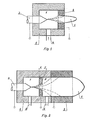
- the plasma torch illustrated in FIG. 3 is, in principle, in accordance with the diagram in FIG. 2 and the corresponding parts are designated by the same numerical references.
- the description relating to FIG. 2 is also applicable to the torch of FIG. 3 and it is therefore not necessary to repeat it.
- the torch of FIG. 3 has several additional characteristics which it is interesting to specify.
- the hot cathode (3) has a pointed head, so as to allow easy lighting of the plasma torch.
- the cathode (3) is furthermore provided with a cooling duct (9) supplied with water in (10).
- the ignition electrode (6) made of copper is also cooled by water, by a circuit which can be put in series with that of the cathode; the cooling water is discharged through the outlet (11).
- the downstream end of the ignition electrode (6) carries a crown in which are formed several passages (4) in the form of conduits or channels, for the introduction of the plasma gas. These passages (4) are uniformly distributed in the crown, their outlet orifices, in the inner surface of the crown, are arranged very close to each other, and are preferably contiguous, so that the plasma gas forms a continuous jet over the entire inner periphery of the crown.
- passages (4) are further oriented substantially tangentially to the inner surface of the crown, so that the outgoing plasma gas is driven in a helical movement in the anode chamber (II).
- the speed of the plasma gas must be at least 50 m / s at the entrance to the anode chamber.
- the anode (2) is provided with a spiral peripheral cooling circuit, consisting of helical fins (12) capped by a tube (13); the cooling water arrives at (14) and is discharged at (15).
- the material of this ring is of current quality; it is for example made up of asbestos, silica, alumina or boron nitride.
- This ring is applied to the downstream end face of the ignition electrode (6), and, if necessary, it closes the channels (4) hollowed out in this face.
- the ring (16) is supported in a shoulder provided in the enclosure (1) and it constitutes the bearing surface of the inlet section of the anode (2).
- the internal diameter of the ring (16) is at least equal to that of the anode (2), and preferably equal to the internal diameter of the anode + 10 mm.
- a pipe (17) for supplying fuel, for example fine coal transported by a gas under pressure Through the body of the plasma torch is formed a pipe (17) for supplying fuel, for example fine coal transported by a gas under pressure.
- the outlet section (18) of this conduit passes through the ignition electrode (6) and opens out inside the ring (16).
- the outlet axis of this section (18) intersects the longitudinal axis of the anode (2) at an angle of about 45 °.
- this torch works in the same way as that of Figure 2.
- a cathode gas inert with respect to tungsten, for example nitrogen, hydrogen, rare gases or a mixture of these gases.
- the plasma gas is introduced at the entrance to the anode chamber (II), through the passages (4) formed in the crown of the ignition electrode (6).
- the fine carbon is introduced in (19) into the conduit (17, 18) and it is injected into the anode chamber (II) in which it passes into the vapor state under the effect of the high temperature, higher than 3500 ° C, prevailing in the plasma jet.
- a fine carbon of the quality known as "for boilers", that is to say having approximately 70% of the grains less than 74 ⁇ m.
- the carbon-carrying gas is preferably air, possibly enriched in nitrogen for well-known explosion safety reasons.
- the injected carbon does not accumulate and does not obstruct the torch, it is almost completely sublimed and it is thus in the form of carbon gas which, injected for example in a blast furnace, reacts very quickly with minerals oxidized and with oxygen from the hot wind.
- the power of the plasma torches of the in vention can be set in three different ways.
- a first means consists in using cathode gases of a different nature. Thus, all other things being equal, the replacement of argon by nitrogen increases the power by about 20%.
- the power is indeed substantially proportional to the intensity of the arc current.
Landscapes
- Physics & Mathematics (AREA)
- Engineering & Computer Science (AREA)
- Plasma & Fusion (AREA)
- Spectroscopy & Molecular Physics (AREA)
- Plasma Technology (AREA)
- Discharge Heating (AREA)
Applications Claiming Priority (2)
| Application Number | Priority Date | Filing Date | Title |
|---|---|---|---|
| BE6/47929A BE898951A (fr) | 1984-02-17 | 1984-02-17 | Torche a plasma a arc electrique. |
| BE6047929 | 1984-02-17 |
Publications (3)
| Publication Number | Publication Date |
|---|---|
| EP0155254A2 true EP0155254A2 (de) | 1985-09-18 |
| EP0155254A3 EP0155254A3 (en) | 1986-03-19 |
| EP0155254B1 EP0155254B1 (de) | 1989-07-12 |
Family
ID=3874937
Family Applications (1)
| Application Number | Title | Priority Date | Filing Date |
|---|---|---|---|
| EP85870025A Expired EP0155254B1 (de) | 1984-02-17 | 1985-02-13 | Lichtbogenplasmabrenner |
Country Status (9)
| Country | Link |
|---|---|
| US (1) | US4596918A (de) |
| EP (1) | EP0155254B1 (de) |
| JP (1) | JPS60189199A (de) |
| AU (1) | AU579851B2 (de) |
| BE (1) | BE898951A (de) |
| BR (1) | BR8500708A (de) |
| CA (1) | CA1230387A (de) |
| DE (1) | DE3571544D1 (de) |
| ZA (1) | ZA851134B (de) |
Cited By (3)
| Publication number | Priority date | Publication date | Assignee | Title |
|---|---|---|---|---|
| FR2654293A1 (fr) * | 1989-11-08 | 1991-05-10 | Aerospatiale | Torche a plasma a injection non refroidie de gaz plasmagene. |
| US5262616A (en) * | 1989-11-08 | 1993-11-16 | Societe Nationale Industrielle Et Aerospatiale | Plasma torch for noncooled injection of plasmagene gas |
| CZ300768B6 (cs) * | 1999-12-09 | 2009-08-05 | Thermal Dynamics Corporation | Plazmový obloukový horák, jeho katoda a elektroda |
Families Citing this family (14)
| Publication number | Priority date | Publication date | Assignee | Title |
|---|---|---|---|---|
| JPH0622719B2 (ja) * | 1985-05-13 | 1994-03-30 | 小野田セメント株式会社 | 複ト−チ型プラズマ溶射方法及びその装置 |
| JPS61259777A (ja) * | 1985-05-13 | 1986-11-18 | Onoda Cement Co Ltd | 単ト−チ型プラズマ溶射方法及び装置 |
| US4995231A (en) * | 1988-02-01 | 1991-02-26 | Olin Corporation | Performance arcjet thruster |
| US4926632A (en) * | 1988-02-01 | 1990-05-22 | Olin Corporation | Performance arcjet thruster |
| US4853515A (en) * | 1988-09-30 | 1989-08-01 | The Perkin-Elmer Corporation | Plasma gun extension for coating slots |
| EP0428671A1 (de) * | 1989-06-08 | 1991-05-29 | Jean Albert François SÜNNEN | Verfahren und vorrichtung zur erhaltung hoher temperaturen |
| FR2654294B1 (fr) * | 1989-11-08 | 1992-02-14 | Aerospatiale | Torche a plasma a amorcage par court-circuit. |
| US20080116179A1 (en) * | 2003-04-11 | 2008-05-22 | Hypertherm, Inc. | Method and apparatus for alignment of components of a plasma arc torch |
| US6946617B2 (en) * | 2003-04-11 | 2005-09-20 | Hypertherm, Inc. | Method and apparatus for alignment of components of a plasma arc torch |
| KR100807806B1 (ko) * | 2006-04-04 | 2008-02-27 | 제주대학교 산학협력단 | 직류 아크 플라즈마트론 장치 및 사용 방법 |
| CN101309546B (zh) * | 2008-07-02 | 2012-12-12 | 北京光耀能源技术股份有限公司 | 交流等离子发射枪 |
| KR101025035B1 (ko) * | 2009-06-23 | 2011-03-25 | 주성호 | 프라즈마를 이용한 버어너 |
| WO2012162562A1 (en) * | 2011-05-24 | 2012-11-29 | Thermal Dynamics Corporation | Plasma arc torch with secondary starting circuit and electrode |
| CN102438387B (zh) * | 2011-09-28 | 2014-12-24 | 南京创能电力科技开发有限公司 | 气旋式低温等离子发生器 |
Family Cites Families (5)
| Publication number | Priority date | Publication date | Assignee | Title |
|---|---|---|---|---|
| GB845410A (en) * | 1955-07-26 | 1960-08-24 | Union Carbide Corp | Improved arc working process and apparatus |
| DE1571153A1 (de) * | 1962-08-25 | 1970-08-13 | Siemens Ag | Plasmaspritzpistole |
| GB1360659A (en) * | 1971-12-09 | 1974-07-17 | British Titan Ltd | Heating device |
| US3832513A (en) * | 1973-04-09 | 1974-08-27 | G Klasson | Starting and stabilizing apparatus for a gas-tungsten arc welding system |
| IT1055884B (it) * | 1976-02-17 | 1982-01-11 | Montedison Spa | Procedimento ad arco plasma di prodotti ceramici metallici e simili |
-
1984
- 1984-02-17 BE BE6/47929A patent/BE898951A/fr unknown
-
1985
- 1985-02-13 EP EP85870025A patent/EP0155254B1/de not_active Expired
- 1985-02-13 DE DE8585870025T patent/DE3571544D1/de not_active Expired
- 1985-02-14 BR BR8500708A patent/BR8500708A/pt unknown
- 1985-02-14 US US06/701,863 patent/US4596918A/en not_active Expired - Fee Related
- 1985-02-14 ZA ZA851134A patent/ZA851134B/xx unknown
- 1985-02-15 CA CA000474456A patent/CA1230387A/en not_active Expired
- 1985-02-18 JP JP60030140A patent/JPS60189199A/ja active Pending
- 1985-02-18 AU AU38930/85A patent/AU579851B2/en not_active Ceased
Cited By (4)
| Publication number | Priority date | Publication date | Assignee | Title |
|---|---|---|---|---|
| FR2654293A1 (fr) * | 1989-11-08 | 1991-05-10 | Aerospatiale | Torche a plasma a injection non refroidie de gaz plasmagene. |
| EP0427591A1 (de) * | 1989-11-08 | 1991-05-15 | AEROSPATIALE Société Nationale Industrielle | Plasmabrenner mit nicht gekühlter Plasmagasinjektion |
| US5262616A (en) * | 1989-11-08 | 1993-11-16 | Societe Nationale Industrielle Et Aerospatiale | Plasma torch for noncooled injection of plasmagene gas |
| CZ300768B6 (cs) * | 1999-12-09 | 2009-08-05 | Thermal Dynamics Corporation | Plazmový obloukový horák, jeho katoda a elektroda |
Also Published As
| Publication number | Publication date |
|---|---|
| US4596918A (en) | 1986-06-24 |
| DE3571544D1 (en) | 1989-08-17 |
| AU579851B2 (en) | 1988-12-15 |
| BE898951A (fr) | 1984-08-17 |
| CA1230387A (en) | 1987-12-15 |
| JPS60189199A (ja) | 1985-09-26 |
| EP0155254A3 (en) | 1986-03-19 |
| AU3893085A (en) | 1985-08-22 |
| BR8500708A (pt) | 1985-10-08 |
| ZA851134B (en) | 1985-09-25 |
| EP0155254B1 (de) | 1989-07-12 |
Similar Documents
| Publication | Publication Date | Title |
|---|---|---|
| EP0155254B1 (de) | Lichtbogenplasmabrenner | |
| EP0576869B1 (de) | Vorrichtung zum Einblasen von Kohlenstaub in einen Hochofen | |
| CH543711A (fr) | Générateur à jet de plasma | |
| FR2577304A1 (fr) | Electrobruleur a gaz a apport d'energie electrique. | |
| CN108608126B (zh) | 等离子分流熔化极弧焊接装置与焊接方法 | |
| WO1999053734A1 (fr) | Torche et procede de coupage ou soudage a l'arc electrique | |
| EP1186211A1 (de) | Plasmabrenner enthaltend durch einen luftspalt getrennte elektroden und einen solchen brenner enthaltender zünder | |
| EP0250308B1 (de) | Plasmaspritzbrenner | |
| WO1992010325A1 (fr) | Ouverture d'un trou de coulee avec une torche a plasma | |
| FR2498409A1 (fr) | Generateur de plasma | |
| RU2206964C1 (ru) | Электродуговой плазмотрон | |
| EP0457994B1 (de) | Gas-Elektrobrenner mit Zufuhr elektrischer Energie und Zündhilfe | |
| EP1147692A1 (de) | Aus kupfer-legierung hergestelltes verschleissteil für lichtbogenbrenner | |
| WO2021160450A1 (fr) | Torche plasma à amorcage direct et tuyère à barrière diélectrique correspondante | |
| FR2601441A1 (fr) | Four rotatif a plasma a alimentation en materiau a traiter a entrainement mecanique | |
| FR2652981A1 (fr) | Generateur de plasma a cathode creuse pour le traitement de poudres par plasma. | |
| EP1181126B1 (de) | Verfahren und anlage zum automatischen mehr-plasmaschweissen | |
| FR2654293A1 (fr) | Torche a plasma a injection non refroidie de gaz plasmagene. | |
| EP3174373B1 (de) | Lichtbogenplasmabrenner mit wolfram-elektrode | |
| EP1578177A1 (de) | Verfahren zum Plasmaschneiden mittels Zweistromgas | |
| FR2986396A1 (fr) | Torche a plasma d'arc avec amelioration du centrage axial de l'electrode | |
| EP0428671A1 (de) | Verfahren und vorrichtung zur erhaltung hoher temperaturen | |
| EP0834049A1 (de) | Schmelzverfahren einer ladung im lichtbogenofen | |
| TW202337274A (zh) | 電漿炬,電漿噴塗裝置,及電漿炬的控制方法 | |
| BE677086A (de) |
Legal Events
| Date | Code | Title | Description |
|---|---|---|---|
| PUAI | Public reference made under article 153(3) epc to a published international application that has entered the european phase |
Free format text: ORIGINAL CODE: 0009012 |
|
| AK | Designated contracting states |
Designated state(s): DE FR GB IT LU NL SE |
|
| PUAL | Search report despatched |
Free format text: ORIGINAL CODE: 0009013 |
|
| AK | Designated contracting states |
Kind code of ref document: A3 Designated state(s): DE FR GB IT LU NL SE |
|
| 17P | Request for examination filed |
Effective date: 19860822 |
|
| 17Q | First examination report despatched |
Effective date: 19880407 |
|
| GRAA | (expected) grant |
Free format text: ORIGINAL CODE: 0009210 |
|
| AK | Designated contracting states |
Kind code of ref document: B1 Designated state(s): DE FR GB IT LU NL SE |
|
| REF | Corresponds to: |
Ref document number: 3571544 Country of ref document: DE Date of ref document: 19890817 |
|
| ITF | It: translation for a ep patent filed | ||
| GBT | Gb: translation of ep patent filed (gb section 77(6)(a)/1977) | ||
| PGFP | Annual fee paid to national office [announced via postgrant information from national office to epo] |
Ref country code: DE Payment date: 19900131 Year of fee payment: 6 |
|
| PGFP | Annual fee paid to national office [announced via postgrant information from national office to epo] |
Ref country code: LU Payment date: 19900223 Year of fee payment: 6 |
|
| ITTA | It: last paid annual fee | ||
| PG25 | Lapsed in a contracting state [announced via postgrant information from national office to epo] |
Ref country code: LU Free format text: LAPSE BECAUSE OF NON-PAYMENT OF DUE FEES Effective date: 19900228 |
|
| PGFP | Annual fee paid to national office [announced via postgrant information from national office to epo] |
Ref country code: NL Payment date: 19900228 Year of fee payment: 6 Ref country code: GB Payment date: 19900228 Year of fee payment: 6 |
|
| PLBE | No opposition filed within time limit |
Free format text: ORIGINAL CODE: 0009261 |
|
| STAA | Information on the status of an ep patent application or granted ep patent |
Free format text: STATUS: NO OPPOSITION FILED WITHIN TIME LIMIT |
|
| 26N | No opposition filed | ||
| REG | Reference to a national code |
Ref country code: FR Ref legal event code: ST |
|
| REG | Reference to a national code |
Ref country code: FR Ref legal event code: RC |
|
| PG25 | Lapsed in a contracting state [announced via postgrant information from national office to epo] |
Ref country code: GB Effective date: 19910213 |
|
| REG | Reference to a national code |
Ref country code: FR Ref legal event code: DA |
|
| PG25 | Lapsed in a contracting state [announced via postgrant information from national office to epo] |
Ref country code: NL Effective date: 19910901 |
|
| GBPC | Gb: european patent ceased through non-payment of renewal fee | ||
| NLV4 | Nl: lapsed or anulled due to non-payment of the annual fee | ||
| PG25 | Lapsed in a contracting state [announced via postgrant information from national office to epo] |
Ref country code: DE Effective date: 19911101 |
|
| PGFP | Annual fee paid to national office [announced via postgrant information from national office to epo] |
Ref country code: SE Payment date: 19950119 Year of fee payment: 11 |
|
| PGFP | Annual fee paid to national office [announced via postgrant information from national office to epo] |
Ref country code: FR Payment date: 19950123 Year of fee payment: 11 |
|
| EAL | Se: european patent in force in sweden |
Ref document number: 85870025.5 |
|
| PG25 | Lapsed in a contracting state [announced via postgrant information from national office to epo] |
Ref country code: SE Effective date: 19960214 |
|
| PG25 | Lapsed in a contracting state [announced via postgrant information from national office to epo] |
Ref country code: FR Effective date: 19961031 |
|
| REG | Reference to a national code |
Ref country code: FR Ref legal event code: ST |