EP0155261B1 - Ventilsteuerung für eine Brennkraftmaschine - Google Patents
Ventilsteuerung für eine Brennkraftmaschine Download PDFInfo
- Publication number
- EP0155261B1 EP0155261B1 EP85890059A EP85890059A EP0155261B1 EP 0155261 B1 EP0155261 B1 EP 0155261B1 EP 85890059 A EP85890059 A EP 85890059A EP 85890059 A EP85890059 A EP 85890059A EP 0155261 B1 EP0155261 B1 EP 0155261B1
- Authority
- EP
- European Patent Office
- Prior art keywords
- valve
- cam
- cams
- valve control
- control according
- Prior art date
- Legal status (The legal status is an assumption and is not a legal conclusion. Google has not performed a legal analysis and makes no representation as to the accuracy of the status listed.)
- Expired
Links
- 238000002485 combustion reaction Methods 0.000 title claims abstract description 22
- 239000002826 coolant Substances 0.000 claims description 3
- 238000010276 construction Methods 0.000 description 5
- 230000008878 coupling Effects 0.000 description 5
- 238000010168 coupling process Methods 0.000 description 5
- 238000005859 coupling reaction Methods 0.000 description 5
- 230000005540 biological transmission Effects 0.000 description 3
- 238000001816 cooling Methods 0.000 description 2
- 230000002349 favourable effect Effects 0.000 description 2
- 230000002028 premature Effects 0.000 description 2
- 230000015572 biosynthetic process Effects 0.000 description 1
- 230000007812 deficiency Effects 0.000 description 1
- 238000006073 displacement reaction Methods 0.000 description 1
- 230000000694 effects Effects 0.000 description 1
- 238000009434 installation Methods 0.000 description 1
- 238000005461 lubrication Methods 0.000 description 1
- 230000000717 retained effect Effects 0.000 description 1
Images


Classifications
-
- F—MECHANICAL ENGINEERING; LIGHTING; HEATING; WEAPONS; BLASTING
- F01—MACHINES OR ENGINES IN GENERAL; ENGINE PLANTS IN GENERAL; STEAM ENGINES
- F01L—CYCLICALLY OPERATING VALVES FOR MACHINES OR ENGINES
- F01L1/00—Valve-gear or valve arrangements, e.g. lift-valve gear
- F01L1/26—Valve-gear or valve arrangements, e.g. lift-valve gear characterised by the provision of two or more valves operated simultaneously by same transmitting-gear; peculiar to machines or engines with more than two lift-valves per cylinder
- F01L1/262—Valve-gear or valve arrangements, e.g. lift-valve gear characterised by the provision of two or more valves operated simultaneously by same transmitting-gear; peculiar to machines or engines with more than two lift-valves per cylinder with valve stems disposed radially from a centre which is substantially the centre of curvature of the upper wall surface of a combustion chamber
-
- F—MECHANICAL ENGINEERING; LIGHTING; HEATING; WEAPONS; BLASTING
- F01—MACHINES OR ENGINES IN GENERAL; ENGINE PLANTS IN GENERAL; STEAM ENGINES
- F01L—CYCLICALLY OPERATING VALVES FOR MACHINES OR ENGINES
- F01L1/00—Valve-gear or valve arrangements, e.g. lift-valve gear
- F01L1/20—Adjusting or compensating clearance
- F01L1/205—Adjusting or compensating clearance by means of shims or the like
-
- F—MECHANICAL ENGINEERING; LIGHTING; HEATING; WEAPONS; BLASTING
- F01—MACHINES OR ENGINES IN GENERAL; ENGINE PLANTS IN GENERAL; STEAM ENGINES
- F01L—CYCLICALLY OPERATING VALVES FOR MACHINES OR ENGINES
- F01L1/00—Valve-gear or valve arrangements, e.g. lift-valve gear
- F01L1/20—Adjusting or compensating clearance
- F01L1/22—Adjusting or compensating clearance automatically, e.g. mechanically
- F01L1/24—Adjusting or compensating clearance automatically, e.g. mechanically by fluid means, e.g. hydraulically
-
- F—MECHANICAL ENGINEERING; LIGHTING; HEATING; WEAPONS; BLASTING
- F01—MACHINES OR ENGINES IN GENERAL; ENGINE PLANTS IN GENERAL; STEAM ENGINES
- F01L—CYCLICALLY OPERATING VALVES FOR MACHINES OR ENGINES
- F01L13/00—Modifications of valve-gear to facilitate reversing, braking, starting, changing compression ratio, or other specific operations
- F01L13/0015—Modifications of valve-gear to facilitate reversing, braking, starting, changing compression ratio, or other specific operations for optimising engine performances by modifying valve lift according to various working parameters, e.g. rotational speed, load, torque
- F01L13/0036—Modifications of valve-gear to facilitate reversing, braking, starting, changing compression ratio, or other specific operations for optimising engine performances by modifying valve lift according to various working parameters, e.g. rotational speed, load, torque the valves being driven by two or more cams with different shape, size or timing or a single cam profiled in axial and radial direction
- F01L13/0042—Modifications of valve-gear to facilitate reversing, braking, starting, changing compression ratio, or other specific operations for optimising engine performances by modifying valve lift according to various working parameters, e.g. rotational speed, load, torque the valves being driven by two or more cams with different shape, size or timing or a single cam profiled in axial and radial direction with cams being profiled in axial and radial direction
-
- F—MECHANICAL ENGINEERING; LIGHTING; HEATING; WEAPONS; BLASTING
- F01—MACHINES OR ENGINES IN GENERAL; ENGINE PLANTS IN GENERAL; STEAM ENGINES
- F01L—CYCLICALLY OPERATING VALVES FOR MACHINES OR ENGINES
- F01L1/00—Valve-gear or valve arrangements, e.g. lift-valve gear
- F01L1/02—Valve drive
- F01L1/04—Valve drive by means of cams, camshafts, cam discs, eccentrics or the like
- F01L1/047—Camshafts
- F01L1/053—Camshafts overhead type
- F01L1/0532—Camshafts overhead type the cams being directly in contact with the driven valve
-
- F—MECHANICAL ENGINEERING; LIGHTING; HEATING; WEAPONS; BLASTING
- F01—MACHINES OR ENGINES IN GENERAL; ENGINE PLANTS IN GENERAL; STEAM ENGINES
- F01L—CYCLICALLY OPERATING VALVES FOR MACHINES OR ENGINES
- F01L1/00—Valve-gear or valve arrangements, e.g. lift-valve gear
- F01L1/02—Valve drive
- F01L1/04—Valve drive by means of cams, camshafts, cam discs, eccentrics or the like
- F01L1/08—Shape of cams
-
- F—MECHANICAL ENGINEERING; LIGHTING; HEATING; WEAPONS; BLASTING
- F01—MACHINES OR ENGINES IN GENERAL; ENGINE PLANTS IN GENERAL; STEAM ENGINES
- F01L—CYCLICALLY OPERATING VALVES FOR MACHINES OR ENGINES
- F01L3/00—Lift-valve, i.e. cut-off apparatus with closure members having at least a component of their opening and closing motion perpendicular to the closing faces; Parts or accessories thereof
- F01L2003/25—Valve configurations in relation to engine
- F01L2003/256—Valve configurations in relation to engine configured other than perpendicular to camshaft axis
-
- F—MECHANICAL ENGINEERING; LIGHTING; HEATING; WEAPONS; BLASTING
- F02—COMBUSTION ENGINES; HOT-GAS OR COMBUSTION-PRODUCT ENGINE PLANTS
- F02B—INTERNAL-COMBUSTION PISTON ENGINES; COMBUSTION ENGINES IN GENERAL
- F02B1/00—Engines characterised by fuel-air mixture compression
- F02B1/02—Engines characterised by fuel-air mixture compression with positive ignition
- F02B1/04—Engines characterised by fuel-air mixture compression with positive ignition with fuel-air mixture admission into cylinder
-
- F—MECHANICAL ENGINEERING; LIGHTING; HEATING; WEAPONS; BLASTING
- F02—COMBUSTION ENGINES; HOT-GAS OR COMBUSTION-PRODUCT ENGINE PLANTS
- F02B—INTERNAL-COMBUSTION PISTON ENGINES; COMBUSTION ENGINES IN GENERAL
- F02B2275/00—Other engines, components or details, not provided for in other groups of this subclass
- F02B2275/18—DOHC [Double overhead camshaft]
-
- F—MECHANICAL ENGINEERING; LIGHTING; HEATING; WEAPONS; BLASTING
- F02—COMBUSTION ENGINES; HOT-GAS OR COMBUSTION-PRODUCT ENGINE PLANTS
- F02F—CYLINDERS, PISTONS OR CASINGS, FOR COMBUSTION ENGINES; ARRANGEMENTS OF SEALINGS IN COMBUSTION ENGINES
- F02F1/00—Cylinders; Cylinder heads
- F02F1/24—Cylinder heads
- F02F1/42—Shape or arrangement of intake or exhaust channels in cylinder heads
- F02F1/4214—Shape or arrangement of intake or exhaust channels in cylinder heads specially adapted for four or more valves per cylinder
-
- F—MECHANICAL ENGINEERING; LIGHTING; HEATING; WEAPONS; BLASTING
- F02—COMBUSTION ENGINES; HOT-GAS OR COMBUSTION-PRODUCT ENGINE PLANTS
- F02F—CYLINDERS, PISTONS OR CASINGS, FOR COMBUSTION ENGINES; ARRANGEMENTS OF SEALINGS IN COMBUSTION ENGINES
- F02F1/00—Cylinders; Cylinder heads
- F02F1/24—Cylinder heads
- F02F2001/244—Arrangement of valve stems in cylinder heads
- F02F2001/245—Arrangement of valve stems in cylinder heads the valve stems being orientated at an angle with the cylinder axis
- F02F2001/246—Arrangement of valve stems in cylinder heads the valve stems being orientated at an angle with the cylinder axis and orientated radially from the combustion chamber surface
Definitions
- the invention relates to a valve control for a reciprocating internal combustion engine with at least one cylinder and with four valves arranged at an angle to one another and actuated by cams of two camshafts in a radial arrangement with respect to the combustion chamber of the cylinder, two of which are one of the two camshafts and the the other two are actuated by the other camshaft, a separate, conical cam being provided for each valve and each valve each having a valve spring and a spring plate.
- hemispherical combustion chambers are sought in internal combustion engines, which require a valve arrangement that is radially oriented with respect to the combustion chamber.
- a particularly advantageous gas exchange is achieved with favorable utilization of the combustion chamber in that two intake and two exhaust valves are provided for each cylinder and that the valves with the same function are diametrically opposed to one another with respect to the cylinder axis.
- camshafts Due to the radial alignment of the valves, camshafts are mainly used for valve actuation, from which the valve lift is derived via bumpers and rocker arms. In such a valve arrangement, the transmission of the lifting movement of conventional control cams of overhead camshafts to the valves is in fact only possible via complex drag and angle levers.
- GB-A 375459 shows an internal combustion engine with two pairs of valves arranged at an angle to one another and radially oriented with respect to the combustion chamber, which can be actuated by means of conically designed cams.
- the transfer of the stroke of the conically shaped cams to the valves takes place, similarly to GE-A 242919, via rocker arms, so that the disadvantages described in connection with DE-B 953 672 occur.
- GE-A 558779 an internal combustion engine with two valves per cylinder is known, which are actuated by a common camshaft arranged above the valves.
- GB-A 558779 also shows an arrangement of the valves in which the axes of the valves do not run parallel but inclined to one another.
- the cam associated with the valve inclined to the axis of the camshaft is conical.
- tappets guided in the cylinder head are provided between the cams - including the conical cams - and the valve, which engage with an adjustable screw on the valve stem.
- tappets of GB-A 558 779 are not cup tappets because they are not cup-shaped and coaxially enclose the valve spring and the valve disk in order to save overall height.
- the tappets of GB-A 558779 are simple sliding cylinders whose high weight caused by the complex valve clearance compensation does not allow the speeds required by modern engines.
- Cup tappets for transferring the cam movement to valves are known (cf. L. Apfelbeck “Paths to high-performance engines” Motorbuch Verlag Stuttgart 1979, chapters V and VII).
- the invention has for its object to avoid these deficiencies and to improve a valve control of the type described in such a way that its advantages can also be used for high-speed internal combustion engines NEN without having to accept the disadvantages of the prior art.
- each camshaft is arranged above the cylinder head and that between each valve and the associated cam there is provided a cup push, which is displaceably guided in the cylinder head and is arranged in the same manner as the valve and is cup-shaped, the valve spring and the spring plate coaxially encloses and on which the associated cam engages directly.
- the cup tappet which is arranged coaxially to the valve stem, can be guided in a bore of the cylinder head that receives the valve spring, so that the transverse forces transmitted from the conical cams to the cup tappet can be transferred to the cylinder head in a simple manner without valve loading. Because of the comparatively large diameter of the guide bore for the cup tappet, the additional load on the tappet guide due to the transverse forces that occur remains within permissible limits, the space required for guiding the cup tappet being advantageously met by the space available with a radial valve arrangement.
- the possible guide length for the cup tappets ensures that the tilting moments occurring during a cam stroke are transferred to the cup tappets. According to a development of the invention, these tilting moments can be avoided if, in the rotational position for the maximum stroke, the cams are pre-curved against the associated bucket tappet from a plane normal to the axis. This means that the bucket tappet is not over-centered even when the cam stroke is full. With a corresponding adjustment to the respective geometrical conditions, the cam curvature can easily achieve that the bucket tappet is always loaded in the center, which allows the bucket tappets to be supported without tilting moment even with comparatively large angles of inclination between the individual valves.
- any desired valve clearance can be set in a simple manner because the distance of the control surface of the cams from the bucket tappet changes when the cams are axially displaced. There is therefore no need to adjust the valve clearance, for example by means of washers between the tappet and the valve stem.
- One possibility of arranging the cams in an axially adjustable manner is to mount the cams on the camshaft in an axially adjustable manner.
- the respective axial position of the cams can be secured, for example, by shaft nuts.
- a further possibility of adjusting the valve clearance can be obtained in that the camshaft is divided and that the partial shafts each having a cam are axially adjustable per se. In this case, the partial shafts of the camshaft must be held axially to fix the set valve clearance, which can be achieved in different ways.
- the arrangement of individually adjustable partial shafts also allows independent adjustment of the valve clearance if the partial shafts of the camshaft are hydraulically adjustable. Particularly simple constructional relationships can be ensured in this way that the partial shafts are acted upon hydraulically via a non-return valve in each case in order to reduce the valve clearance, because the axial position of the respective partial shaft is retained when the non-return valve closes after adjustment.
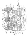
- the internal combustion engine shown consists essentially of a cylinder 1, the cylinder head 2 of which has two intake valves 3 and two exhaust valves 4, the arrangement being such that the valves with the same function are diametrically opposed with respect to the cylinder axis.
- the valves 3, 4 are aligned radially with respect to the combustion chamber, which is closed off by a spherical cap, so that the axes of the valve stems 5 intersect at the center of the ball defining the spherical cap.
- These valves 3 and 4 are assigned in pairs to a camshaft 6 which carries conically shaped cams 7.
- the cam stroke is transmitted to the valve stems 5 via a tappet 8, which is cup-shaped and coaxially encloses the valve spring 9 and the spring plate 10.
- This tappet is in a bore 11 of the Zy Lindenkopfes 2 coaxially guided to the valve stems 5, so that the transverse forces transmitted from the conical cams 7 to the tappet 8 can be transferred to the cylinder head 2 via the wall of the bore 11. Since the bucket tappet 8 lies loosely on the valve stem 5, only a power transmission in the direction of the axis of the valve stem 5 is possible, but not transversely to it.
- the conically shaped cams 7 are pre-curved against the associated bucket tappet 8 in the rotational position for the maximum stroke in the elevation region from a plane normal to the axis, so that the bucket tappet 8 does not become eccentric from the cam during the stroke can be overrun.
- the load on the tappet 8 therefore remains central in every stroke position.
- the camshaft 6 is divided into two partial shafts 6a and 6b, each part being axially displaceably mounted in the cylinder head 2. These two partial shafts 6a and 6b are connected to one another in a rotationally fixed but axially displaceable manner via an axially fixed coupling piece 12, namely a multi-groove connection exists between the partial shafts 6a, 6b and the coupling piece 12.
- the desired valve clearance is set by an axial adjustment of the partial shafts 6a, 6b, washers 13 of corresponding thickness in the form of half rings are inserted between the coupling piece 12 and the shaft collars 14 for fixing the position before the partial shafts are axially clamped together with the coupling piece 12 via a tension bolt 15 will.
- centrifugal forces that occur as a result of centrifugal forces 13 being prevented are prevented by an axially projecting edge projection of the shaft collars 14 that surrounds the washers on the outside.
- the adjustment of the valve clearance can therefore be carried out without complex and time-consuming removal and installation work, it not being necessary to readjust the valve timing.
- FIG. 4 even allows an independent valve lash adjustment in that the partial shafts 6a, 6b of the camshaft 6 are acted upon hydraulically.
- the partial shafts 6a, 6b are connected to pressure cylinders 16, which can be supplied with pressure oil from the lubrication system of the engine via channels 17 provided in the coupling piece 12 and check valves 19 inserted into axial through bores 18 of the partial shafts.
- a flow channel 20 for a cooling medium can be kept free between the two camshafts 6 and the valves 3 and 4 assigned to these camshafts, which also creates favorable cooling conditions in the area of the central spark plug 21, especially in air-cooled engines .
Landscapes
- Engineering & Computer Science (AREA)
- Mechanical Engineering (AREA)
- General Engineering & Computer Science (AREA)
- Chemical & Material Sciences (AREA)
- Combustion & Propulsion (AREA)
- Valve-Gear Or Valve Arrangements (AREA)
- Valve Device For Special Equipments (AREA)
- Lubrication Of Internal Combustion Engines (AREA)
Description
- Die Erfindung betrifft eine Ventilsteuerung für eine Hubkolben-Brennkraftmaschine mit wenigstens einem Zylinder und mit vier im Zylinderkopf zueinander geneigt angeordneten, von Nocken zweier Nockenwellen betätigten Ventilen in radialer Anordnung in bezug auf den Brennraum des Zylinders, von denen zwei von einer der beiden Nockenwellen und die anderen zwei von der anderen Nockenwelle betätigt werden, wobei für jedes Ventil ein separater, konisch ausgebildeter Nocken vorgesehen ist und jedes Ventil je eine Ventilfeder und einen Federteller aufweist.
- Um vorteilhafte Verbrennungen sicherzustellen, werden bei Brennkraftmaschinen halbkugelförmige Verbrennungsräume angestrebt, die eine bezüglich des Verbrennungsraumes radial ausgerichtete Ventilanordnung bedingen. Ein besonders vorteilhafter Gaswechsel wird dabei unter günstiger Ausnützung des Verbrennungsraumes dadurch erreicht, dass je Zylinder zwei Einlass- und zwei Auslassventile vorgesehen sind und dass die Ventile gleicher Funktion einander bezüglich des Zylinderachse diametral gegenüberliegen. Aufgrund der radialen Ausrichtung der Ventile bieten sich für die Ventilbetätigung vor allem untenliegende Nockenwellen an, von denen der Ventilhub über Stossstangen und Kipphebel abgeleitet wird. Die Übertragung der Hubbewegung üblicher Steuernocken obenliegender Nockenwellen auf die Ventile ist nämlich bei einer solchen Ventilanordnung nur über aufwendige Schlepp- und Winkelhebel möglich. Trotz der Anwendung untenliegender Nockenwellen kann eine entsprechende Ventilsteuerung für schnellaufende Brennkraftmaschinen nicht gewährleistet werden, weil sich auf Grund der zu bewegenden Massen keine genauen Ventilsteuerzeiten übertragen lassen. Wegen der vergleichsweise niedrigen Flattergrenze der Ventile ist das Erreichen hoher Motordrehzahlen unmöglich.
- Um bei zueinander geneigt angeordneten Ventilen eine aufwendige Antriebsverbindung zwischen der Nockenwelle und den Ventilen zu vermeiden, ist es bekannt (GB-A 266442), die Nokken kegelförmig auszubilden und unmittelbar auf den Federteller der Ventile einwirken zu lassen. Nachteilig bei dieser Konstruktion ist allerdings, dass die von den kegelförmigen Nocken auf die Federteller übertragenen Querkräfte über die Ventilführung abgetragen werden müssen, was zu einem vorzeitigen Verschleiss der Ventilführungen führt. Da ausserdem während eines Hubes eine Relativverschiebung der Nocken gegenüber den Federtellern in Richtung der Berührungslinie zwischen den Nocken und den Federtellern auftritt, werden die Federteller durch ein Kippmoment belastet, was die Anwendung einer solchen Ventilsteuerung für Ventile mit einem grösseren Neigungswinkel ausschliesst, so dass diese bekannte Konstruktion für bezüglich des Verbrennungsraumes radial ausgerichtete Ventile unbrauchbar ist.
- Zur Verringerung der Baulänge eines Reihenmotors ist es weiters bekannt (DE-B 953 672), die in einer Reihe hintereinander angeordneten Ventile abwechselnd nach entgegengesetzten Richtungen zu neigen und über eine gemeinsame Nockenwelle mit kegelförmigen Nocken anzutreiben, wobei der Hub der Nocken über je einen Schlepphebel auf den Ventilschaft übertragen wird, um die Übertragung von Querkräften auf die Ventilschäfte zu vermeiden. Diese bekannte Konstruktion ist wegen der Schlepphebel zwischen den kegelförmigen Nocken und den Ventilen aufwendig, wobei das Problem besteht, die Schlepphebel so zu lagern, dass die auftretenden Querkräfte abgetragen werden können, ohne einen vorzeitigen Verschleiss der Schlepphebellagerung in Kauf nehmen zu müssen. Ausserdem ist bei dieser bekannten Konstruktion der Abstand der einzelnen Ventile voneinander durch die angestrebte Beschränkung der Baulänge begrenzt, so dass eine hinsichtlich des Verbrennungsraumes radiale Ausrichtung der Ventile nicht möglich ist.
- Die GB-A 375459 zeigt eine Brennkraftmaschine mit zwei Paar zueinander geneigt angeordneten, bezüglich des Verbrennungsraumes radial ausgerichteten Ventilen, die mittels konisch ausgebildeter Nocken betätigbar sind. Die Übertragung des Hubes der konisch ausgebildeten Nokken auf die Ventile erfolgt, ähnlich wie bei der GE-A 242919 über Kipphebel, so dass die im Zusammenhang mit der DE-B 953 672 geschilderten Nachteile auftreten.
- Aus der GE-A 558779 ist eine Brennkraftmaschine mit zwei Ventilen je Zylinder bekannt, die von einer gemeinsam, oberhalb der Ventile angeordneten Nockenwelle betätigt werden. Dabei ist in Fig. der GB-A 558779 auch eine Anordnung der Ventile gezeigt, bei der die Achsen der Ventile nicht parallel, sondern geneigt zueinander verlaufen. Dabei ist die dem zur Achse der Nockenwelle geneigten Ventil zugeordnete Nokke konisch ausgebildet. Zwischen den Nocken - auch den konischen Nocken - und dem Ventil sind bei der GB-A 558 779 in einer Führung im Zylinderkopf geführte Stössel vorgesehen, die über eine einstellbare Schraube am Ventilschaft angreifen. Diese Stössel der GB-A 558 779 sind keine Tassenstössel, weil sie nicht topfartig ausgebildet sind und die Ventilfeder und den Ventilteller koaxial umschliessen, um Bauhöhe zu sparen. Die Stössel der GB-A 558779 sind einfache Gleitzylinder, deren durch den aufwendigen Ventilspielausgleich bewirktes hohes Gewicht keine von modernen Motoren geforderte Drehzahlen zulässt.
- Tassenstössel zur Übertragung der Nockenbewegung auf Ventile sind bekannt (vgl. L. Apfelbeck «Wege zum Hochleistungsmotor» Motorbuch Verlag Stuttgart 1979, Kapitel V und VII).
- Der Erfindung liegt die Aufgabe zugrunde, diese Mängel zu vermeiden und eine Ventilsteuerung der eingangs geschilderten Art so zu verbessern, dass ihre Vorteile auch für schnellaufende Brennkraftmaschinen ausgenützt werden können, ohne die beim Stand der Technik auftretenden Nachteile in Kauf nehmen zu müssen.
- Die Erfindung löst die gestellte Aufgabe dadurch, dass jede Nockenwelle oberhalb des Zylinderkopfes angeordnet ist und dass zwischen jedem Ventil und dem zugeordneten Nocken ein im Zylinderkopf verschiebbar geführter, gleichachsig mit dem Ventil angeordneter Tassenstössei vorgesehen ist, der topfartig ausgebildet ist, die Ventilfeder und den Federteller koaxial umschliesst und an dem der zugehörige Nocken unmittelbar angreift.
- Durch das Vorsehen von Tassenstösseln zwischen den konisch ausgebildeten Nocken und den Ventilen kann die über den Nockenantrieb zu bewegende zusätzliche Masse vergleichsweise klein gehalten werden, so dass diesbezüglich die erreichbare Motordrehzahl nicht beschränkt wird. Dazu kommt, dass der koaxial zum Ventilschaft angeordnete Tassenstössel in einer die Ventilfeder aufnehmenden Bohrung des Zylinderkopfes geführt werden kann, so dass die von den konisch ausgebildeten Nocken auf den Tassenstössel übertragenen Querkräfte in einfacher Weise ohne Ventilbelastung auf den Zylinderkopf abgetragen werden können. Wegen des vergleichsweise grossen Durchmessers der Führungsbohrung für die Tassenstössel bleibt die zusätzliche Belastung der Stösselführung durch die auftretenden Querkräfte in zulässigen Grenzen, wobei dem Platzbedarf für die Führung des Tassenstössels durch das Platzangebot bei radialer Ventilanordnung vorteilhaft entsprochen werden kann.
- Die mögliche Führungslänge für die Tassenstössel gewährleistet ein Abtragen der während eines Nockenhubes auftretenden Kippmomente auf den Tassenstössel. Diese Kippmomente lassen sich gemäss einer Weiterbildung der Erfindung vermeiden, wenn in der Drehstellung für den maximalen Hub die Nocken im Erhebungsbereich aus einer achsnormalen Ebene gegen den zugehörigen Tassenstössel vorgekrümmt sind. So wird der Tassenstössel auch bei vollem Nokkenhub nicht aussermittig überlaufen. Durch die Nockenkrümmung kann bei einer entsprechenden Abstimmung auf die jeweiligen geometrischen Verhältnisse in einfacher Weise erreicht werden, dass der Tassenstössel stets mittig belastet wird, was auch bei vergleichsweise grossen Neigungswinkeln zwischen den einzelnen Ventilen eine kippmomentfreie Lagerung der Tassenstössel erlaubt.
- Sind in weiterer Ausbildung der Erfindung die Nocken axial verstellbar, so kann in einfacher Weise jedes gewünschte Ventilspiel eingestellt werden, weil sich bei einer axialen Verschiebung der Nocken der Abstand der Steuerfläche der Nocken vom Tassenstössel ändert. Es entfällt daher die Notwendigkeit, das Ventilspiel beispielsweise durch Beilagscheiben zwischen Tassenstössel und Ventilschaft einzustellen.
- Eine Möglichkeit, die Nocken axial verstellbar anzuordnen, besteht darin, die Nocken auf der Nockenwelle axial verstellbar zu lagern. Dabei kann die jeweilige Axiallage der Nocken beispielsweise durch Wellenmuttern gesichert werden. Eine weitere Einstellmöglichkeit des Ventilspieles kann dadurch erhalten werden, dass die Nockenwelle geteilt ist und dass die je einen Nokken aufweisenden Teilwellen für sich axial verstellbar sind. Zur Fixierung des eingestellten Ventilspieles sind in diesem Fall die Teilwellen der Nockenwelle axial festzuhalten, was auf unterschiedliche Weise erreicht werden kann.
- Die Anordnung von je für sich verstellbare Teilwellen erlaubt darüber hinaus eine selbständige Nachstellung des Ventilspieles, wenn die Teilwellen der Nockenwelle hydraulisch verstellbar sind. Besonders einfache Konstruktionsverhältnisse können dabei dadurch sichergestellt werden, dass die Teilwellen im Sinne einer Verkleinerung des Ventilspieles hydraulisch über je ein Rückschlagventil beaufschlagt werden, weil mit dem einer Nachstellung folgenden Schliessung des Rückschlagventiles die axiale Lage der jeweiligen Teilwelle erhalten bleibt.
- Die Übertragung des Nockenhubes auf die Ventilschäfte über im Zylinderkopf verschiebbar gelagerte Tassenstössel ermöglicht schliesslich bei der Anordnung von vier radial angeordneten Ventilen, denen paarweise eine gemeinsame Nockenwelle mit kegelförmigen Nocken zugeordnet ist, die Ausbildung eines Strömungskanales für ein Kühlmedium zwischen den beiden Nockenwellen, so dass für eine vorteilhafte Kühlung des Zylinderkopfes auch im Bereich der Zündkerze gesorgt werden kann.
- In der Zeichnung ist der Erfindungsgegenstand beispielsweise dargestellt. Es zeigen
- Fig. 1 eine erfindungsgemässe Ventilsteuerung für eine Brennkraftmaschine in einer schematischen Draufsicht auf einen Zylinderkopf,
- Fig. 2 einen Schnitt nach der Linie 11-11 der Fig. 1,
- Fig. 3 einen Teilschnitt nach der Linie 111-111 der Fig. 2 und
- Fig. 4 eine Konstruktionsvariante in einem der Fig. 3 entsprechenden Schnitt.
- Die dargestellte Brennkraftmaschine besteht im wesentlichen aus einem Zylinder 1, dessen Zylinderkopf 2 zwei Einlassventile 3 und zwei Auslassventile 4 aufweist, wobei die Anordnung so getroffen ist, dass sich die Ventile gleicher Funktion bezüglich der Zylinderachse diametral gegenüberliegen. Die Ventile 3, 4 sind dabei hinsichtlich des Verbrennungsraumes, der durch eine Kugelkalotte abgeschlossen wird, radial ausgerichtet, so dass sich die Achsen der Ventilschäfte 5 im Mittelpunkt der die Kugelkalotte bestimmenden Kugel schneiden. Diesen Ventilen 3 und 4 ist paarweise eine Nockenwelle 6 zugeordnet, die konisch ausgebildete Nocken 7 trägt. Die Übertragung des Nockenhubes auf die Ventilschäfte 5 erfolgt jeweils über einen Tassenstössel 8, der topfartig ausgebildet ist und die Ventilfeder 9 und den Federteller 10 koaxial umschliesst. Dieser Tassenstössel ist in einer Bohrung 11 des Zylinderkopfes 2 koaxial zu den Ventilschäften 5 verschiebbar geführt, so dass die von den kegelförmigen Nocken 7 auf die Tassenstössel 8 übertragenen Querkräfte über die Wandung der Bohrung 11 auf den Zylinderkopf 2 abgetragen werden können. Da der Tassenstössel 8 lose am Ventilschaft 5 anliegt, ist lediglich eine Kraftübertragung in Richtung der Achse des Ventilschaftes 5, nicht aber quer dazu möglich.
- Wie insbesondere Fig.3 und 4 entnommen werden kann, sind die konisch ausgebildeten Nocken 7 in der Drehstellung für den maximalen Hub im Erhebungsbereich aus einer achsnormalen Ebene gegen den zugehöhrigen Tassenstössel 8 vorgekrümmt, so dass der Tassenstössel 8 während des Hubes nicht aussermittig von dem Nocken überlaufen werden kann. Die Belastung des Tassenstössels 8 bleibt daher in jeder Hublage zentrisch.
- Zum Einstellen des Ventilspieles ist die Nokkenwelle 6 gemäss Fig. 3 in zwei Teilwellen 6a und 6b geteilt, wobei jeder Teil für sich axial verschiebbar im Zylinderkopf 2 gelagert ist. Diese beiden Teilwellen 6a und 6b sind über ein axial festgelegtes Kupplungsstück 12 miteinander drehfest, aber axial verschiebbar verbunden, und zwar besteht zwischen den Teilwellen 6a, 6b und dem Kupplungsstück 12 eine Vielnutverbindung. Das gewünschte Ventilspiel wird durch eine axiale Verstellung der Teilwellen 6a, 6b eingestellt, wobei zur Lagefixierung Beilagscheiben 13 entsprechender Stärke in Form von Halbringen zwischen dem Kupplungsstück 12 und den Wellenbunden 14 eingelegt werden, bevor die Teilwellen mit dem Kupplungstück 12 über einen Zugbolzen 15 axial zusammengespannt werden. Das Abschleudern der Beilagscheiben 13 zufolge auftretender Zentrifugalkräfte wird dabei durch einen die Beilagscheiben aussen umgreifenden, axial vorragenden Randansatz der Wellenbunde 14 verhindert. Die Einstellung des Ventilspieles kann daher ohne aufwendige und zeitraubende Aus-und Einbauarbeiten durchgeführt werden, wobei es keiner neuerlichen Einstellung der Ventilsteuerzeiten bedarf.
- Die in Fig. 4 veranschaulichte Konstruktion erlaubt sogar eine selbständige Ventilspielnachstellung, indem die Teilwellen 6a, 6b der Nockenwelle 6 hydraulisch beaufschlagt werden. Zu diesem Zweck sind die Teilwellen 6a, 6b mit Druckzylindern 16 verbunden, die über im Kupplungsstück 12 vorgesehene Kanäle 17 und in axiale Durchgangsbohrungen 18 der Teilwellen eingesetzte Rückschlagventile 19 mit Drucköl aus dem Schmiersystem des Motors versorgt werden können. Bewegt sich ein Nocken 7 im Bereich seines Grundkreises über den Tassenstössel 8, so wird ein allenfalls vorhandenes Spiel zwischen dem Nocken und dem Tassenstössel ausgeglichen, weil das Drucköl über das Rückschlagventil 19 zum Druckzylinder 16 strömen und die Teilwelle im Sinne einer Spielverkleinerung axial verstellen kann, bis auf Grund des sich im Druckzylinder 16 aufbauenden Druckes sich das Rückschlag- ventil wieder rer axialen Lage festgehalten wird. Leckverluste, die sich durch einen Druckabbau im Druckzylinder 16 bemerkbar machen, wenn sich der Nocken im Bereich seines Grundkreises über den Tassenstössel bewegt, werden unmittelbar ausgeglichen, weil sich in einem solchen Fall das Rückschlagventil 19 wieder öffnet. Die hydraulische Beaufschlagung der Teilwellen 6a, 6b im Sinne einer Spielverkleinerung zwischen den Tassenstösseln 8 und den Nocken 7 bewirkt somit ein ständiges Anliegen der Tassenstössel 8 an den Nocken 7, was sich vorteilhaft auf die Laufruhe und die Belastung der Nocken und der Tassenstössel auswirkt.
- Wie insbesondere die Fig.2 erkennen lässt, kann zwischen den beiden Nockenwellen 6 und den diesen Nockenwellen zugeordneten Ventilen 3 und 4 ein Strömungskanal 20 für ein Kühlmedium freigehalten werden, was günstige Kühlbedingungen auch im Bereich der zentralen Zündkerze 21 schafft, vor allem bei luftgekühlten Motoren.
Claims (8)
Applications Claiming Priority (2)
| Application Number | Priority Date | Filing Date | Title |
|---|---|---|---|
| AT0084384A AT382933B (de) | 1984-03-14 | 1984-03-14 | Ventilbetaetigung fuer hubkolben - brennkraftmaschinen |
| AT843/84 | 1984-03-14 |
Publications (4)
| Publication Number | Publication Date |
|---|---|
| EP0155261A2 EP0155261A2 (de) | 1985-09-18 |
| EP0155261A3 EP0155261A3 (en) | 1987-01-07 |
| EP0155261B1 true EP0155261B1 (de) | 1989-06-14 |
| EP0155261B2 EP0155261B2 (de) | 1996-03-20 |
Family
ID=3501045
Family Applications (1)
| Application Number | Title | Priority Date | Filing Date |
|---|---|---|---|
| EP85890059A Expired - Lifetime EP0155261B2 (de) | 1984-03-14 | 1985-03-12 | Ventilsteuerung für eine Brennkraftmaschine |
Country Status (4)
| Country | Link |
|---|---|
| US (1) | US4635592A (de) |
| EP (1) | EP0155261B2 (de) |
| AT (2) | AT382933B (de) |
| DE (1) | DE3571061D1 (de) |
Families Citing this family (18)
| Publication number | Priority date | Publication date | Assignee | Title |
|---|---|---|---|---|
| AT399021B (de) * | 1985-03-18 | 1995-03-27 | Weichsler Hermann | Ventilsteuerung für brennkraftmaschinen |
| AT400971B (de) * | 1985-10-17 | 1996-05-28 | Bombardier Rotax Gmbh | Ventilsteuerung für einen zylinder einer brennkraftmaschine |
| AT404388B (de) * | 1986-02-20 | 1998-11-25 | Weichsler Hermann | Brennkraftmaschine |
| DE3818636A1 (de) * | 1988-06-01 | 1989-12-07 | Bayerische Motoren Werke Ag | Hubkolben-brennkraftmaschine mit einem zwei obenliegende steuerwellen umfassenden zylinderkopf |
| DE3838305A1 (de) * | 1988-11-11 | 1990-05-17 | Audi Ag | Zylinderkopf einer brennkraftmaschine |
| US5016592A (en) * | 1989-02-14 | 1991-05-21 | Yamaha Hatsudoki Kabushika Kaisha | Cylinder head and valve train arrangement for multiple valve engine |
| US4982705A (en) * | 1990-02-21 | 1991-01-08 | Tecumseh Products Company | Cam pulley and cylinder head arrangement for an overhead cam engine |
| FR2668797A1 (fr) * | 1990-11-05 | 1992-05-07 | Silvetti Gabriel | Culasse pour moteurs thermiques avec soupapes a levee variable. |
| EP0867601B1 (de) * | 1997-03-27 | 2003-01-22 | Toyota Jidosha Kabushiki Kaisha | Ventilsteuerung für eine Brennkraftmaschine |
| DE19731974B4 (de) | 1997-07-24 | 2006-09-07 | Peter Pelz | Hubkolbenbrennkraftmaschine |
| JP3493296B2 (ja) * | 1997-11-25 | 2004-02-03 | 茂 長野 | エンジン |
| DE69913251T2 (de) * | 1998-06-24 | 2004-05-27 | Yamaha Hatsudoki K.K., Iwata | Ventilsteuerungseinrichtung für eine Brennkraftmaschine |
| US6170449B1 (en) * | 1998-09-30 | 2001-01-09 | Yamaha Hatsudoki Kabushiki Kaisha | Valve operating system for engine |
| JP4627121B2 (ja) * | 2001-06-12 | 2011-02-09 | ヤマハ発動機株式会社 | 三次元カムおよび三次元カム用研削装置 |
| JP4201617B2 (ja) * | 2003-02-24 | 2008-12-24 | 本田技研工業株式会社 | 内燃機関 |
| DE102007032638A1 (de) * | 2007-07-11 | 2009-01-15 | Bayerische Motoren Werke Aktiengesellschaft | Brennkraftmaschine mit einer Kurbelwelle und wenigstens einem Zylinderkopf sowie Kraftfahrzeug mit einer derartigen Brennkraftmaschine |
| DE102007052251A1 (de) * | 2007-11-02 | 2009-05-07 | Daimler Ag | Ventiltriebvorrichtung |
| CN103277209B (zh) * | 2013-06-08 | 2015-08-19 | 清华大学 | 单缸机交叉气道缸盖总成结构 |
Family Cites Families (17)
| Publication number | Priority date | Publication date | Assignee | Title |
|---|---|---|---|---|
| FR327184A (fr) * | 1902-12-09 | 1903-06-16 | Filtz Joseph | Mécanisme de commande des soupapes d'un moteur à explosion |
| GB226442A (en) * | 1924-06-12 | 1924-12-24 | Montague Stanley Napier | Improvements in or relating to internal combustion engines |
| GB242919A (en) * | 1925-07-10 | 1925-11-19 | Napier & Son Ltd | Improvements in or relating to valve operating mechanism for internal combustion engines |
| GB375459A (en) * | 1931-04-07 | 1932-06-30 | Frank Albert George Butters | Improvements in or relating to the valve mechanism of internal combustion engines |
| GB467320A (en) * | 1935-12-20 | 1937-06-15 | Ludwig Apfelbeck | Improvements in cylinder-heads for internal combustion engines |
| GB558779A (en) * | 1943-05-19 | 1944-01-20 | Harold Raymond Morgan | Improvements in combustion chambers and overhead valve gear in internal combustion engines |
| DE953672C (de) * | 1952-05-07 | 1956-12-06 | Daimler Benz Ag | Ventilsteuerung fuer Brennkraftmaschinen |
| US3481314A (en) * | 1967-08-29 | 1969-12-02 | Georges G Lecrenn | Means for optimizing the performance of internal combustion engines |
| US3638624A (en) * | 1970-04-13 | 1972-02-01 | Donald J O Grady | Engine valve control means |
| US3730150A (en) * | 1971-10-20 | 1973-05-01 | S Codner | Method and apparatus for control of valve operation |
| DE2300827A1 (de) * | 1973-01-09 | 1974-07-11 | Keller Edmund | Ventilbetaetigungssystem einer hubkolbenbrennkraftmaschine |
| GB1505643A (en) * | 1975-05-20 | 1978-03-30 | British Leyland Uk Ltd | Internal combustion engine |
| JPS5261618A (en) * | 1975-11-17 | 1977-05-21 | Nissan Motor Co Ltd | Open and close time control mechanism for inlet or exhaust valve of in ternal combustion engine |
| JPS538415A (en) * | 1976-07-13 | 1978-01-25 | Toyota Motor Corp | Hydraulic valve lifter assembly for overhead cam-type engine |
| JPS5596310A (en) * | 1979-01-12 | 1980-07-22 | Nissan Motor Co Ltd | Valve rocking device |
| JPS5838603B2 (ja) * | 1979-07-03 | 1983-08-24 | 日産自動車株式会社 | 内燃機関のバルブリフト装置 |
| JPS57210126A (en) * | 1981-06-19 | 1982-12-23 | Yamaha Motor Co Ltd | High pressure gas fuel engine |
-
1984
- 1984-03-14 AT AT0084384A patent/AT382933B/de not_active IP Right Cessation
-
1985
- 1985-03-07 US US06/709,761 patent/US4635592A/en not_active Expired - Lifetime
- 1985-03-12 EP EP85890059A patent/EP0155261B2/de not_active Expired - Lifetime
- 1985-03-12 AT AT85890059T patent/ATE44074T1/de active
- 1985-03-12 DE DE8585890059T patent/DE3571061D1/de not_active Expired
Also Published As
| Publication number | Publication date |
|---|---|
| EP0155261A2 (de) | 1985-09-18 |
| US4635592A (en) | 1987-01-13 |
| ATA84384A (de) | 1986-09-15 |
| EP0155261B2 (de) | 1996-03-20 |
| DE3571061D1 (en) | 1989-07-20 |
| AT382933B (de) | 1987-04-27 |
| EP0155261A3 (en) | 1987-01-07 |
| ATE44074T1 (de) | 1989-06-15 |
Similar Documents
| Publication | Publication Date | Title |
|---|---|---|
| EP0155261B2 (de) | Ventilsteuerung für eine Brennkraftmaschine | |
| DE4492633C1 (de) | Stößel | |
| DE69105721T2 (de) | Ventilsteuervorrichtung. | |
| DE69014818T2 (de) | Kugelförmige Drehschieber für Brennkraftmaschine. | |
| DE3613912C2 (de) | ||
| DE2101665C3 (de) | Ventilsteuerung fur Brennkraft maschinen | |
| DE19606054C2 (de) | Ventiltrieb einer Brennkraftmaschine | |
| DE2428951A1 (de) | Ventiltrieb fuer einen verbrennungsmotor mit oben liegender nockenwelle und dafuer bestimmte ventilnachstellvorrichtung | |
| WO1996021801A1 (de) | Schaltbares abstützelement | |
| DE69101185T2 (de) | Steuervorrichtung, insbesondere für eine Brennkraftmaschine mit einer Anzahl von Ventilen je Zylinder. | |
| DE3624108C2 (de) | ||
| DE3635110A1 (de) | Ventilsteuereinrichtung fuer eine brennkraftmaschine | |
| DE19908286A1 (de) | Variable Ventilsteuerung für Brennkraftmaschinen | |
| DE2061481A1 (de) | Ventilbetatigungsmechanismus fur eine Maschine mit einem periodisch betätigten Tellerventil | |
| DE69012056T2 (de) | Zylinderköpfe für brennkraftmaschinen. | |
| DE69913251T2 (de) | Ventilsteuerungseinrichtung für eine Brennkraftmaschine | |
| DE4213147C2 (de) | Variabler Ventiltrieb für ein Hubventil mit zwei durch unterschiedliche Nocken betätigbaren Stößeln | |
| DE3611476A1 (de) | Verfahren zur betaetigung von ventilen zum ladungswechsel bei brennkraftmaschinen mit direkter hydraulischer uebertragung | |
| DE4202542A1 (de) | Variabler ventiltrieb fuer ein hubventil | |
| EP0353543B1 (de) | Ventilsteuerung für Brennkraftmaschinen | |
| DE4030568C2 (de) | ||
| DE10055595A1 (de) | Verfahren und Vorrichtung zur Zylinderabschaltung bei Verbrennungsmotoren | |
| DE3521539A1 (de) | Vorrichtung fuer eine nockengesteuerte hubkolbenmaschine | |
| DE4204997A1 (de) | Ventiltrieb fuer ein hubventil | |
| DE19744600A1 (de) | Abschaltbarer Ventiltrieb für Brennkraftmaschinen |
Legal Events
| Date | Code | Title | Description |
|---|---|---|---|
| PUAI | Public reference made under article 153(3) epc to a published international application that has entered the european phase |
Free format text: ORIGINAL CODE: 0009012 |
|
| AK | Designated contracting states |
Designated state(s): AT DE FR GB IT |
|
| RAP1 | Party data changed (applicant data changed or rights of an application transferred) |
Owner name: WEICHSLER, HERMANN |
|
| RIN1 | Information on inventor provided before grant (corrected) |
Inventor name: WEICHSLER, HERMANN |
|
| PUAL | Search report despatched |
Free format text: ORIGINAL CODE: 0009013 |
|
| AK | Designated contracting states |
Kind code of ref document: A3 Designated state(s): AT DE FR GB IT |
|
| 17P | Request for examination filed |
Effective date: 19861223 |
|
| 17Q | First examination report despatched |
Effective date: 19871028 |
|
| ITF | It: translation for a ep patent filed | ||
| GRAA | (expected) grant |
Free format text: ORIGINAL CODE: 0009210 |
|
| RAP1 | Party data changed (applicant data changed or rights of an application transferred) |
Owner name: WEICHSLER, HERMANN |
|
| AK | Designated contracting states |
Kind code of ref document: B1 Designated state(s): AT DE FR GB IT |
|
| REF | Corresponds to: |
Ref document number: 44074 Country of ref document: AT Date of ref document: 19890615 Kind code of ref document: T |
|
| GBT | Gb: translation of ep patent filed (gb section 77(6)(a)/1977) | ||
| REF | Corresponds to: |
Ref document number: 3571061 Country of ref document: DE Date of ref document: 19890720 |
|
| ET | Fr: translation filed | ||
| PG25 | Lapsed in a contracting state [announced via postgrant information from national office to epo] |
Ref country code: AT Effective date: 19900312 |
|
| PLBI | Opposition filed |
Free format text: ORIGINAL CODE: 0009260 |
|
| PLBI | Opposition filed |
Free format text: ORIGINAL CODE: 0009260 |
|
| 26 | Opposition filed |
Opponent name: DR. ING. H. C. F. PORSCHE AKTIENGESELLSCHAFT Effective date: 19900312 |
|
| 26 | Opposition filed |
Opponent name: BAYERISCHE MOTOREN WERKE AG, PATENTABTEILUNG AJ-3, Effective date: 19900314 Opponent name: DR. ING. H. C. F. PORSCHE AKTIENGESELLSCHAFT Effective date: 19900312 |
|
| PUAH | Patent maintained in amended form |
Free format text: ORIGINAL CODE: 0009272 |
|
| STAA | Information on the status of an ep patent application or granted ep patent |
Free format text: STATUS: PATENT MAINTAINED AS AMENDED |
|
| 27A | Patent maintained in amended form |
Effective date: 19960320 |
|
| AK | Designated contracting states |
Kind code of ref document: B2 Designated state(s): AT DE FR GB IT |
|
| EN | Fr: translation not filed | ||
| GBV | Gb: ep patent (uk) treated as always having been void in accordance with gb section 77(7)/1977 [no translation filed] |
Effective date: 19890614 |
|
| REG | Reference to a national code |
Ref country code: GB Ref legal event code: 710B |
|
| GBTA | Gb: translation of amended ep patent filed (gb section 77(6)(b)/1977) | ||
| REG | Reference to a national code |
Ref country code: GB Ref legal event code: 710B |
|
| REG | Reference to a national code |
Ref country code: FR Ref legal event code: RN |
|
| ET3 | Fr: translation filed ** decision concerning opposition | ||
| REG | Reference to a national code |
Ref country code: FR Ref legal event code: FC |
|
| REG | Reference to a national code |
Ref country code: GB Ref legal event code: IF02 |
|
| PGFP | Annual fee paid to national office [announced via postgrant information from national office to epo] |
Ref country code: FR Payment date: 20040304 Year of fee payment: 20 |
|
| PGFP | Annual fee paid to national office [announced via postgrant information from national office to epo] |
Ref country code: DE Payment date: 20040305 Year of fee payment: 20 |
|
| PGFP | Annual fee paid to national office [announced via postgrant information from national office to epo] |
Ref country code: GB Payment date: 20040309 Year of fee payment: 20 |
|
| PG25 | Lapsed in a contracting state [announced via postgrant information from national office to epo] |
Ref country code: GB Free format text: LAPSE BECAUSE OF EXPIRATION OF PROTECTION Effective date: 20050311 |
|
| REG | Reference to a national code |
Ref country code: GB Ref legal event code: PE20 |
|
| APAH | Appeal reference modified |
Free format text: ORIGINAL CODE: EPIDOSCREFNO |