EP0155285B1 - Tonfrequenzkanalschichtung mit sprachkompression für schmalbandübertragung für gewählte anrufe - Google Patents
Tonfrequenzkanalschichtung mit sprachkompression für schmalbandübertragung für gewählte anrufe Download PDFInfo
- Publication number
- EP0155285B1 EP0155285B1 EP84903251A EP84903251A EP0155285B1 EP 0155285 B1 EP0155285 B1 EP 0155285B1 EP 84903251 A EP84903251 A EP 84903251A EP 84903251 A EP84903251 A EP 84903251A EP 0155285 B1 EP0155285 B1 EP 0155285B1
- Authority
- EP
- European Patent Office
- Prior art keywords
- frequency
- channel
- signals
- bandwidth
- sideband
- Prior art date
- Legal status (The legal status is an assumption and is not a legal conclusion. Google has not performed a legal analysis and makes no representation as to the accuracy of the status listed.)
- Expired - Lifetime
Links
- 230000005540 biological transmission Effects 0.000 title claims abstract description 32
- 230000006835 compression Effects 0.000 title claims description 23
- 238000007906 compression Methods 0.000 title claims description 23
- 238000001228 spectrum Methods 0.000 claims abstract description 59
- 238000004891 communication Methods 0.000 claims abstract description 12
- 238000000034 method Methods 0.000 claims abstract description 12
- 230000010363 phase shift Effects 0.000 claims description 11
- 230000009977 dual effect Effects 0.000 claims description 6
- 230000008878 coupling Effects 0.000 claims 3
- 238000010168 coupling process Methods 0.000 claims 3
- 238000005859 coupling reaction Methods 0.000 claims 3
- 238000012545 processing Methods 0.000 abstract description 8
- 238000010586 diagram Methods 0.000 description 8
- 230000008569 process Effects 0.000 description 5
- 238000006243 chemical reaction Methods 0.000 description 3
- 230000004048 modification Effects 0.000 description 2
- 238000012986 modification Methods 0.000 description 2
- 230000011664 signaling Effects 0.000 description 2
- 230000005236 sound signal Effects 0.000 description 2
- 230000009466 transformation Effects 0.000 description 2
- 230000001131 transforming effect Effects 0.000 description 2
- 230000008901 benefit Effects 0.000 description 1
- 239000000969 carrier Substances 0.000 description 1
- 230000006735 deficit Effects 0.000 description 1
- 238000001514 detection method Methods 0.000 description 1
- 230000000694 effects Effects 0.000 description 1
- 238000005516 engineering process Methods 0.000 description 1
- 238000001914 filtration Methods 0.000 description 1
- 230000036540 impulse transmission Effects 0.000 description 1
- 238000011084 recovery Methods 0.000 description 1
- 230000009467 reduction Effects 0.000 description 1
- 238000012546 transfer Methods 0.000 description 1
- 238000004804 winding Methods 0.000 description 1
Images





Classifications
-
- H—ELECTRICITY
- H04—ELECTRIC COMMUNICATION TECHNIQUE
- H04J—MULTIPLEX COMMUNICATION
- H04J1/00—Frequency-division multiplex systems
- H04J1/02—Details
- H04J1/08—Arrangements for combining channels
-
- H—ELECTRICITY
- H04—ELECTRIC COMMUNICATION TECHNIQUE
- H04B—TRANSMISSION
- H04B1/00—Details of transmission systems, not covered by a single one of groups H04B3/00 - H04B13/00; Details of transmission systems not characterised by the medium used for transmission
- H04B1/66—Details of transmission systems, not covered by a single one of groups H04B3/00 - H04B13/00; Details of transmission systems not characterised by the medium used for transmission for reducing bandwidth of signals; for improving efficiency of transmission
Definitions
- This invention relates to communication systems for sending information by transmission between stations over a limited band circuit such as, for example, a telephone line or telephone voice grade circuit.
- the invention provides for sending a plurality of separate messages each of which occupy the available known bandwidth under normal conditions but by means of the present invention a plurality of such messages can be sent over a communication circuit which has a bandwidth approximately the same as that of the individual messages.
- the invention is adapted to send a plurality of telephone voice messages over an ordinary dialed telephone line or circuit which has approximately a 3 kHz bandwidth.
- Analog voice multiplexing is also employed for increasing communication line utilization through a technique known as Time Assigned Speech Interpolation (TASI) in which the various conversations are analyzed to insert the multiple messages for one channel in the gaps during pauses and between words found in the other messages.
- TASI Time Assigned Speech Interpolation
- this manipulation is done in digital form with the result reconverted to analog for transmission, thereby eliminating the need for modems or data sets.
- US-A-2,726,283 shows a technique for reducing band requirements in transmission systems wherein the original speech frequency spectrum is separated into two approximately equal ranges, the higher range is converted to the same level as the lower range by means of product modulation. The two ranges are then transmitted on a time-sharing basis in an alternating sequence, each within associated time slots equal to a half cycle of the fundamental wave of the original wide band signal. It is further suggested to use the upper half of the original bandwidth for transmitting another speech channel in a similar manner wherein the the lower range of the original speech frequency spectrum is converted to the same level as the higher range and wherein its spectrum is inverted for effecting speech privacy during transmission.
- US-A-3,349,184 shows an arrangement for bandwidth compression and expansion by frequency division and multiplication and in connection with FIGS. 20 - 22 thereof discloses a five channel system with the subchannels proportioned to occupy a 3 kHz transmission bandwidth.
- the present invention provides for frequency band stacking of the multiple analog signals utilizing speech compression and expansion and includes arrangements which permit telephone dialing to establish dialed up circuits for simultaneous telephone calls on a single voice circuit.
- each message signal is compressed for transforming the signal to a fractional portion of its normal spectrum.
- the compressed baseband signal can be directly passed to a summing unit.
- the remaining channels have the compressed signal applied to introduce frequency offset, such as by modulating the information signal on a carrier and extracting the suppressed carrier sideband information signal which is then demodulated at an offset frequency before being applied to the summing device.
- a plurality of information signals such as a plurality of voice messages, each of which originally had a spectrum approximately equal to the bandwidth of the communication circuit to be employed for transmission, can be reduced in frequency by a factor equal to the number of channels to be transmitted, and those reduced frequency information signals can be stacked in contiguous bands to occupy the bandwidth of the transmission circuit.
- the contiguous frequency band signals can be separated by appropriate filters and the offset frequency signals transfered to occupy baseband or other normal position in the spectrum before the signals are passed through speech expansion means for restoring each signal to its normal frequency spectrum on its individual output terminal.
- the principal object of the present invention to provide an improved simple and economical system which permits multiple channel analog signals to be transmitted over a narrowband communication circuit without the requirement for digital processing or computer capability while maintaining high quality two-way communication for the multiple channels over a single circuit between the transmitting and receiving points.
- the system When used for telephone signals the system maintains voice quality reception for normal conversation and voice recognition while multiplying the number of voice channels available over each voice grade circuit and permits normal dialing to establish the desired circuit connection.
- FIG. 1 is a block diagram showing a typical application of the invention to double line capacity in a dedicated or private line system, or a dial selected circuit connection.
- FIG. 2 is a block diagram of a compression-stacker-expander as used in the system of FIG. 1 providing two-channel capacity over a single two-way circuit for two-way conversations on both channels.
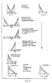
- FIG. 3 shows the analog spectrum for a two-channel system at various stages as the signal is processed for transmission through a system of the type shown in FIG. 2.
- FIG. 4 is a set of spectrum diagrams showing the processing of two channel signals of the type described in FIG. 3 upon reception as they pass through a system of the type shown in FIG. 2.
- FIG. 5 is a block diagram of an alternative form of frequency offset circuit for use in the system in accordance with the invention.
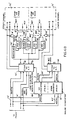
- FIGS. 6A and 6B assembled as indicated, are a block diagram of a system with provision for dial-through connection on the dial telephone network with stacking of two simultaneous two-way messages on a single trunk line.
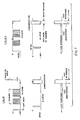
- FIG. 7 shows the E and M convention for single frequency dialing for an ordinary dialed telephone connection with indication of when the voice compression and expansion circuits of the present invention would be in use or bypass during dialing.
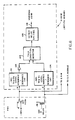
- FIG. 8 is a block diagram of the unbypass logic for switching a dialed connection to stacked transmission condition.
- FIG. 9 is a block diagram of the down-converter used in FIG. 6.
- FIG. 10 is a block diagram of the up-converter used in the system of FIg. 6.
- FIG. 1 the overall application of the invention to provide dual channel two-way communication between remote stations on a typical single narrowband line will be described.
- ordinary PBX or CBX stations 11 and 12 represent existing telephone equipment servicing a plurality of office telephones and local lines.
- a single dedicated or dialed line 13 is provided to interconnect the two.
- stacker units 14 constructed in accordance with the invention. Each stacker 14 handles two lines from telephone sets in its respective PBX and processes both of its lines for both incoming and outgoing messages on line 13, thereby doubling the capacity of line 13, as will be described.
- FIG. 2 a stacker 14 of the type used in the system of FIG. 1 will be described.
- the system of the invention utilizes devices which are capable of compression and expansion of audio analog signals.
- the nomenclature of the patent to Schiffman, 3,786,195, will be used.
- a system for fast or slow playback of recorded speech is disclosed with speech compression and expansion units used to convert the spectrum of the speech signal into its normal frequency band.
- speech compression and expansion are utilized in real time and the various known forms of such frequency transformation of analog signals, such as those disclosed in the Schiffman patent and subsequent patents of the assignee, the Variable Speech Control Company, can be utilized.
- speech compression consists of reducing the frequency of an incoming signal by a factor 1/c, where c has a value greater than 1.
- Speech expansion is defined as transforming the spectrum of an incoming speech signal to increase the frequency by a factor 1/c, where c has values greater than 0 but less than 1.
- FIG. 2 a system for handling two channels A and B is shown.
- a lowpass filter 16 having this characteristic passes the compressed channel A signal to one input of a summing device 17.
- the second channel, channel B is applied to a similar speech compression unit 18, the output of which is at half frequency and half spectrum width at 125-1600 Hz, which signal is applied as one input to a balanced modulator 19.
- the other input to the balanced modulator 19 is a carrier frequency, for example 455.0 kHz, obtained from a suitable source such as oscillator 21 and divider 22.
- the output of balanced modulator 19 contains upper and lower sidebands which when applied to a sideband filter 23 produce as an output signal the suppressed carrier lower sideband at (455.0 - 1.6) kHz which is applied to a balanced demodulator 24.
- the second input to demodulator 24 is the offset carrier at 451.8 kHz derived from an oscillator 25 and divider 26.
- the output of the demodulator 24 is applied to a bandpass filter 27 having a passband of 1625-3200 Hz and this signal is applied as another input to the summing circuit 17.
- the summing circuit 17 supplies the channel A signal compressed to half spectrum width and occupying the band from 125 to 1600 Hz while the signal of channel B is compressed to one half its spectrum width and occupies the band from 1625 to 3200 Hz.
- FIG. 3 shows the spectrum of the analog speech signal at various points as it is subject to frequency transformation.
- the column entitled “Channel A” shows audio input as covering the spectrum from 250 to 3200 Hz which when compressed by a factor of 2 occupies the spectrum from 125 to 1600 Hz. That same signal after filtering in filter 16 appears as the channel A portion of the combined output in FIG. 3.
- the original and compressed spectrum signals appear the same as those in channel A.
- the 1600 Hz compressed speech signal is modulated on the 455.0 kHz carrier the double sideband signal centered at 455.0 kHz is obtained, and the lower sideband is selected by filter 23 which may be a sharply tuned mechanical filter.
- the demodulation in demodulator 24 is with respect to a carrier frequency of 451.8 kHz which has the effect of moving the selected lower sideband spectrum higher by 1.6 kHz, thereby creating a spectrum component which is offset by that amount to occupy the spectrum from 1.6 to 3.2 kHz.
- This is the signal that appears at the output of bandpass filter 27, and, when applied to the summing circuit 17, produces the B component of the combined channel A and B signals on terminal 28.
- each of the original audio input signals which both occupy the 3 kHz band of the available telephone line or other communication circuit have been compressed to occupy one half of that spectrum and one of the channels has been offset by an amount equal to one half the band so that the two can be transmitted simultaneously, each occupying a contiguous half of the available bandwidth.
- Stacked channel A and B signals of the type just described when transmitted from terminal 28 of FIG. 2 to a telephone line, are received at a remote receiving station at an input terminal 31, as shown in FIG. 2, where the contiguous frequency bands are separated by a bandpass filter 32, operating at the upper half of the band, and a lowpass filter 33 passing signals in the lower half of the band.
- the lower band signals from the filter 33 are applied to a speech expansion unit 34 which converts the 125-1600 Hz input signal to a full spectrum 250-3200 Hz voice audio signal.
- bandpass filter 32 is the upper half spectrum of the transmitted signal occupying the bend from 1625-3200 Hz and this signal is applied as one input to a balanced modulator 36.
- the other input to the balanced modulator 36 is the 451.8 kHz carrier which produces at the output of modulator 36 the upper and lower sidebands centered on this carrier frequency which are applied to a sideband filter 37.
- the upper sideband is selected by the sharply tuned filter 37, and this sideband is applied as one input to a balanced demodulator 38, the other input of which is the carrier frequency 455.0 kHz.
- This demodulation process produces at its output a signal component in the band 125-1600 Hz, and this signal band is passed by lowpass filter 39 and applied to a speech expansion unit 41.
- the full spectrum signal of channel A is recovered on output terminal 35 as previously described and the full spectrum output signal of channel B is recovered at terminal 42 to provide two separate telephone message signals.
- FIG. 4 shows the spectrum processing through the receiver portion of FIG. 2.
- stacked A and B spectrum signals are received and by means of the lowpass filter channel A is separated, and after passing through its separate speech expander 34 appears as the full spectrum channel A output signal.
- the processing steps to recover channel B from a received signal are also shown in FIG. 4.
- the bandpass filter 32 separates the channel B spectrum from 1625-3200 Hz and the balanced modulator 36 operating with an injected carrier of 451.8 kHz produces the upper and lower sidebands separated from 451.8 kHz into the spectrum 1.5 to 3.2 kHz above and -3.2 to -1.5 kHz below the carrier frequency.
- the sideband filter selects the upper sideband which is above the 451.8 kHz carrier by +1.5 to +3.2 kHz.
- This single sideband suppressed carrier signal is then demodulated in demodulator 38 against a 455.0 kHz carrier to produce the compressed channel B signal at baseband from 0 to 1.6 kHz. Passing this signal through a low pass filter 39 and speech expander 41 produces the desired full spectrum channel B signal at 3.2 kHz baseband.
- each of the stackers 14 receives the channel A and B inputs from its PBX 11 or 12, respectively, and supplies its channel A and B outputs to these separate telephone sets or other devices which are using the line.
- the stacked output terminal. 28 and stacked input terminal 31 are connected at the local ends of the voice grade circuit 13.
- the invention can be practiced by other means for generating offset sidebands of compressed speech signals.
- FIG. 5 a modification is shown wherein a pair of balanced modulators 51 and 52 receive the compressed channel B signal from speech compressor 18 after it passes through an audio 90° phase shift network 54.
- the 455.0 kHz carrier also passes through a 90° phase shift network 55 before the 455.0 kHz carriers at 90° phase relation are applied respectively to the balanced modulators 51 and 52.
- the resulting sideband outputs from modulators 51 and 52 are applied to a signal combiner 56 which operates to cancel the upper sideband and enhance the lower sideband so that only the lower sideband signal is applied to a balanced demodulator 57.
- the lower sideband signal applied to demodulator 57 is demodulated with respect to the 451.8 kHz carrier to recover a demodulated spectrum from 1625-3200 Hz which is selected by bandpass filter 27 and coupled as an input to summing circuit 17.
- the recovery of the individual channel A and B signals from a stacked input in the system of FIG. 5 is achieved in an analogous manner to that just described for stacking and again with the components that correspond to those described for FIG. 2 having the same reference numbers primed.
- the stacked channel A input signal passes through lowpass filter 33' and speech expander 34' to produce the normal spectrum and frequency channel A output at terminal 35'.
- the channel B spectrum of the stacked input signal in FIG. 5 is selected by bandpass filter 32' and applied to an audio 90° phase shift network 64 which produces the signal at two outputs with 90° phase relation, which signals are applied respectively to balanced modulators 61 and 62.
- the balanced modulator 61 and 62 operate with respect to the 451.8 kHz carrier which is applied thereto with 90° phase shift from a carrier phase shift network 65.
- the outputs of the modulator 61 and 62 are applied to a signal combiner 66 wherein the lower sideband is suppressed and the suppressed carrier upper sideband is enhanced and applied to a balanced demodulator 67.
- the invention has been described as applied to voice telephone circuits where two independent voice frequency signals can be accommodated or stacked for transmission over a single voice frequency circuit, the invention is not limited to doubling the narrowband transmission circuit capacity.
- Such high compression ratios are available with the technology such as disclosed in the referenced Schiffman patent and related patents which are assigned to the assignee of that patent.
- the techniques for speech compression and expansion which are disclosed in US-A-4,700,391 and US-A-4,792,975 can be employed in the present invention, and when so employed provide extremely high quality speech compression, expansion and reproduction in real time for narrowband transmission.
- This form of speech compression and expansion is particularly well suited for real time voice circuits since the referenced copending applications control signal processing by detecting the glottal pulse signal derived from the speech signal and achieve a natural splicing between successive samples of the speech signal.
- the natural glottal pulse epoch splicing is of particular advantage.
- the invention is not limited to telephone wire line circuits but can be applied to band limited transmission circuits of any type. Although the invention has been described with reference to voice circuits it is not so limited, and can be applied to transmit various analog signal forms without the complexity and expanse of digital techniques.
- the transmission medium may also be radio or other form of radiant energy wherein the system of the type disclosed in FIG. 2 would be interposed to process the audio or analog input signal to deliver the desired stacked messages to the modulator of any conventional communications system. The corresponding unstacking of the demodulated signal at the receiver would produce at the receiver the separate channel signals which were stacked and transmitted.
- FIG. 6A a system terminal for use with a local PBX to double the channel capacity for trunk calls which are dialed in a routine manner is shown.
- the PBX can assign two calls to a given trunk line and these connections will be made locally to an upper channel unit 70 or a lower channel 71, each of which has connections for the transmission (XMIT) and reception (RCV) of a voice message and the E and M leads for ON HOOK and OFF HOOK signals and impulse dialing.
- XMIT transmission
- RCV reception
- FIG. 6A it is assumed that there is an identical unit at the remote terminal to which a call is being placed and that the two simultaneous messages which can be transmitted by the system will be received by the selected telephone set connected to upper channel and lower channel units 70' and 71' at the remote terminal of FIG. 6B by the PBX during the dialing hookup sequence. Since FIG. 6B is in this and all other respects identical with FIG. 6A, only FIG. 6A will be described and the corresponding elements in FIG. 6B will be assigned corresponding reference numerals primed.
- Signalling between PBX's through a trunk circuit is normally accomplished by the E and M convention.
- the M lead transmits battery or ground signals to the signalling system.
- the E lead receives open or ground signals from the trunk.
- the near end condition of the trunk is indicated by the M lead and the far end condition by the E lead.
- a 2600 Hz single frequency inband signal is used for dial impulse transmission since the trunk circuit can be a carrier channel where DC cannot be transmitted.
- upper channel unit 70 has E and M leads which are connected to a conventional single frequency generator 72 which produces the 2600 Hz signal on the outgoing line 73 to the trunk.
- the 2600 Hz signal on incoming line 74 is converted by the single frequency unit 72 to the appropriate E and M line conditions in upper channel unit 70.
- the upper channel unit 70 receives the caller's voice signal on terminals XMIT which also receive the dual tone multifrequency (DTMF) dialing tones if the caller's set employs touchtone dialing.
- the XMIT terminals are passed directly through a switch 76X to a stacker 77 for application to the outgoing line 73.
- the signal from the unstacker 79 passes through a switch 76R which in the position shown in FIG. 6A bypasses the VSC unit 80 to avoid processing tone dialing signals and in the alternate position switch 76R receives the voice signals after frequency expansion in the unit 80.
- the invention provides for a second simultaneous voice conversation over the same trunk line from a calling set which is connected to lower channel unit 71 with the voice signal applied to the XMIT terminals and the receiver connected to the RCV terminals of unit 71.
- unit 70 if the telephone set connected to unit 71 employs DTMF dialing, those phone signals are also connected to the XMIT terminals of unit 71.
- Either type audio signals connected to XMIT terminals in unit 71 pass through a switch connection 86X to SF unit 72 from which they are applied to the outgoing trunk line 73.
- the lower channel unit 71 has E and M terminals for impulse dialing which are connected to a single frequency unit 82 where the dialing impulses are converted to 2600 Hz and applied to a down-converter 81. Since the upper channel unit 70 is employing the normal 2600 Hz dialing impulses for E and M line dialing it is necessary to distinguish the dialing signals from the lower channel unit 71. This is accomplished in a down-converter 81 which receives the 2600 Hz signal on line 90 from single frequency unit 82 in the form of impulses as determined by the E and M lines of lower channel unit 71.
- the 2600 Hz input signals on line 90 to dawn-converter 81 appear on output line 83 as 1400 Hz impulses or tone indicating the condition of the E and M lines in lower channel unit 71.
- the 1400 Hz signals on line 83 are applied to the outgoing trunk line 73.
- Incoming 1400 Hz signals from a remote lower channel 71' unit which are received on line 74 of the trunk line are applied by line 84 to an up-converter 85 where the 1400 Hz tone impulses are converted to corresponding 2600 Hz signals.
- These 2600 Hz signals from up-converter 85 are applied on line 89 to the SF unit 82 for indicating the condition of the called remote telephone set, i.e., ON HOOK or OFF HOOK.
- the SF to voice logic disables the 1400 Hz notch filter when voice transmission takes place.
- the notch filter is necessary because during dialing by the caller, the SF from the far side is notched out so the caller cannot hear it.
- the absence of the 1400 Hz on line 84 at the up converter 85 enables the SF to voice logic to bypass the notch filter for voice signals from the far side.
- the switching for signals in upper channel unit 70 is controlled in accordance with the condition of an AND circuit 91 which has as inputs the E and M leads of upper channel 70.
- the switching for signals of lower channel unit 71 is controlled in accordance with the condition of an AND circuit 92 which is determined by the inputs thereto from the E and M leads of lower channel unit 71.
- FIG. 6B As previously stated, all elements of the called station are equiped with corresponding structure and function and such a called station is illustrated in FIG. 6B with the elements numbered with primed reference characters corresponding to those used in FIG. 6A.
- FIGS. 6A and 6B interconnected by a trunk circuit 73, 74, and referring to the impulse dialing sequence of FIG. 7, the establishing of a voice circuit between a calling and a called set will be described. Assuming that the calling party is at the station of FIG. 6A and that the PBX has connected the calling telephone set to the terminals of upper channel unit 70. Referring to FIG.
- the caller's M lead goes from 0 to -48 volts when the receiver goes OFF HOOK, and the dialing impulses are generated by the normal dial switch.
- the condition of M line in unit 70 is transmitted via the single frequency unit 72 to the called number at FIG. 6B where the switching of the M lead at the caller's station changes the E lead at the called station from open to 0, as indicated.
- the dialed number selects the circuit to the appropriate called telephone set in the usual manner, and when the called number goes OFF HOOK its M lead changes from 0 to -48 volts. Going OFF HOOK at the called set causes the E lead for the caller's set to go from open to 0.
- the voice frequency signal stacked in the upper half of the channel bandwidth is incoming on line 73' and emerges from the SF unit 72' to be unstacked in unit 79' and have its frequency restored by the VSC expender 80' which doubles the frequency components of its input signal.
- the full frequency voice message thus reaches the RCV terminals of upper channel 70' of FIG. 6B from the VSC unit 80'.
- the reverse process occurs for voice messages originating at the XMIT terminals of upper channel unit 70' in FIG. 6B.
- Such signals are reduced in bandwidth by VSC compression unit 78' and stacked in the upper half of the channel bandwidth by STACK unit 77' for transmission on trunk line 74' to line 74 in FIG. 6A.
- the voice signals emerge from SF unit 72 at terminal 75 and they are unstacked at unit 79 and expanded in VSC unit 80 to produce a full frequency voice signal at the RCV terminals of upper channel unit 70.
- a second voice message circuit can be achieved on the same trunk line 73, 74 using lower channel unit 71 and its associated circuits.
- the PBX will assign the next call to lower channel 71 and the E and M dialing sequence will appear on the E and M leads of unit 71.
- the SF converter 82 converts the impulses to 2600 Hz tones and in this instance, since 2600 Hz is above the lower channel upper limit, a down-converter 81 converts the 2600 Hz impulse signals into 1400 Hz signals on line 83.
- the trunk line 73 which has a notch filter to eliminate the 1400 Hz tone from the conversation which is being conducted on the upper channel.
- the incoming 1400 Hz signal on line 73' of FIG. 6B passes through an up-converter 85' to restore the impulses to 2600 Hz on lead 89' so that the dialing impulses can pass through the SF unit 82' and be recognized by the normal telephone single frequency dialing equipment of the lower channel 71'.
- the reverse path from the E and M leads of lower channel unit 71' produce 2600 Hz from SF unit 82' which is down converted in unit 81' to 1400 Hz at line 83' for transmission on trunk line 74'.
- the received signal is in the lower half of the channel bandwidth and only needs to be expanded in VSC unit 87' without unstacking to be restored to a full frequency voice signal at RCV terminals in lower channel unit 71'.
- the voice message originating at the set connected to lower channel unit 71' in FIG. 6B traces an analogous path back to the receiver RCV terminals of lower channel unit 71 in FIG. 6A with VSC compression for sending and VSC expansion upon reception, but without stacking or unstacking at either end of the line.
- FIGS. 6A and 6B the speech compression and expansion and the stacking and unstacking are accomplished in the manner described herein with reference to FIGS. 1 - 4.
- the upper channel of FIGS. 6A and 6B would correspond to channel B, while the lower channel of FIGS. 6A and 6B would correspond to channel A.
- dialing tones are applied to the XMIT terminals of the calling station, such as upper channel 70 of FIG. 6A.
- the highest frequency used in DTMF dialing is 1477 Hz, hence the dialing tones in the upper channel are stacked in unit 77 to transmit tones equal to (3200-F DTMF ) which is the lower sideband when the input signal is applied for stacking in the system of FIG. 1.
- 3200-F DTMF 3200-F DTMF
- the calling PBX switches the M lead from ground to -48 volts. As shown in FIG. 8, this OFF HOOK condition of the calling set is applied on the M lead to a level interface and debounce circuit 101. Where the switched levels are converted to ⁇ 5 volts and applied through an inverter 102 to a talk condition detector 103.
- the E lead of the calling station is normally open for the ON HOOK condition and goes OFF HOOK (winks) to signal the called end is ready to receive dialing information.
- a level interface and debounce circuit 104 converts the -48 to ground signal on the E lead into ⁇ 5 volts which is applied directly to talk condition detector 103.
- talk condition detector 103 senses the OFF HOOK condition for both the E and M circuit its output goes high and this output is fed to a detect delay circuit 105 which provides approximately a one second delay to prevent the VSC from being unbypassed by the wink back signal. After this delay the output of detect delay 105 operates the unbypass switching to the VSC units 91, 92 and 91', 92' of FIGS. 6A and 6B by its output signal on lead 106.
- the called end of the circuit by going OFF HOOK unbypasses VSC for both ends by creating OFF HOOK conditions on the E&M leads on both ends.
- a 1400 Hz signal is generated in a 1400 Hz oscillator 110 and fed to a tone gate circuit where the 1400 Hz signal is gated on and off and adjusted to the level of the input SF tone.
- the output of the tone gate 111 is then passed through a low pass filter 113 to provide a sine wave in line 83 of Fig. 6A.
- the transmit 2600 Hz SF signal on line 80 is detected by a PLL tone detector 114 and a debounced logic output is used to control the tone gate 111 as follows.
- the SF is amplified in amplifier 115 and fed to an envelope detector 116 and level detector 117 to develop a logic signal representing the high SF tone level.
- These two logic signals from tone detector 114 and SF level detector 117 are used in the tone gate circuit 111 to gate the 1400 Hz SF signal on and off at output line 83 and adjust its level to follow the input SF tone on line 80.
- the SF is a supervisory signal during ON HOOK condition. It is generated at the E&M to SF module by presence of the ground condition of the M lead.
- the SF goes from a -20dbm level (during ON HOOK) to no SF (excess of -100dbm).
- the pulsing of the "M" lead causes the turning on of the SF to a level of -8dbm (12dbm higher than the supervisory level).
- the dialer low channel receive SF down converter will be described.
- the low channel receive signal which contains both voice and SF information is fed to the input of this circuit on line 84.
- an ANTI TALK OFF circuit 121 is employed.
- the signals on line 84 are first separated by means of a high pass filter 122 for the SF tone and low pass filters 123, 123', in the ANTI TALK OFF circuit.
- a logic signal is produced by a tone detector 125 whenever 1400 Hz. is present at the proper level.
- the voice signal is squared up in detector 126 and the positive edges used to trigger a retriggerable monostable 127 providing a more distinct indication of the presence of voice.
- the two logic signals are then fed to a SF tone detect logic 128 where they are used to provide an SF detected signal to turn a tone gate 129 on and off.
- the output of a 2600 Hz oscillator 131 is fed to the tone gate 129 where it is turned off and on by the SF detect logic signal and the level adjusted by the level detection circuits 132 and 133 similar to units 116 and 117 previously described.
- the gated SF 2600 Hz tone is then passed through low pass filters 134, 134' to provide a sine wave output on line 89 which follows the input SF tone level.
Landscapes
- Engineering & Computer Science (AREA)
- Computer Networks & Wireless Communication (AREA)
- Signal Processing (AREA)
- Reduction Or Emphasis Of Bandwidth Of Signals (AREA)
- Telephonic Communication Services (AREA)
Claims (7)
- Einrichtung zur Zweiweg-Übertragung zweier Telefongespräche zwischen den Enden einer Fernleitung, wobei an jedem Ende dieser Leitung folgendes vorgesehen ist:
ein erster und ein zweiter Sprachkanal-Eingangsanschluß, der jeweils mit einem entsprechenden Sprachkompressor verbunden ist, um das Spektrum der Sprachsignale in jedem Kanal auf die Hälfte der Frequenzbandbreite der Fernleitung zu komprimieren;
eine Anordnung zum Stapeln der komprimierten Spektren in zwei aneinander angrenzende Teilbänder des Frequenzbandes der Fernleitung und zum Koppeln der gestapelten Information auf den abgehenden Anschluß der Fernleitung;
eine Anordnung zum Entstapeln der beiden gestapelten Informations-Teilbänder, die von einem ankommenden Anschluß der Fernleitung empfangen werden und jeweils komprimierte Sprachsignale eines entsprechenden Sprachkanals enthalten, und
einen ersten und einen zweiten Sprachexpandierer zum Expandieren der Bandbreite des Spektrums jedes der entstapelten Teilbänder auf die ursprüngliche, nichtkomprimierte Bandbreite des jeweiligen Sprachkanals, dadurch gekennzeichnet, daß die Stapelanordnung enthält:
einen ersten Trägerfrequenzoszillator (21, 22; 21', 22') zum Erzeugen einer bezüglich des Sprachspektrums hohen ersten Frequenz,
eine erste Modulier- und Seitenbandwählanordnung (19, 23; 54, 51, 52, 55, 56), die auf das komprimierte Sprachsignal des zweiten Kanals (B) und die erste Trägerfrequenz anspricht, um ein Ausgangssignal zu erzeugen, welches das trägerunterdrückte untere Seitenband des mit dem komprimierten Sprachsignal modulierten Trägers der ersten Frequenz umfaßt;
eine Anordnung (25, 26; 25', 26') zum Erzeugen eines zweiten Trägers, der um die Bandbreite der Fernleitung bezüglich der ersten Trägerfrequenz versetzt ist;
eine erste symmetrische Demodulatoranordnung (24; 57), die auf das Untere-Seitenband-Signal und die zweite Trägerfrequenz anspricht, um das komprimierte Sprachsignal des zweiten Kanals (B) um die Hälfte der Fernleitungsbandbreite versetzt zu erzeugen;
eine Anordnung (27; 27') zum Wählen des unteren Seitenbandes, welches in die obere Hälfte des Fernleitungsfrequenzbandes versetzt ist;
eine Anordnung (17, 17') zum Summieren des komprimierten Sprachsignals der unteren Frequenzbandhälfte im ersten Kanal (A) mit dem versetzten komprimierten Sprachsignal des zweiten Kanals (B) in der oberen Frequenzbandhälfte, um ein Ausgangssignal aus den vereinigten Signalen der oberen und unteren Frequenzbandhälfte an den abgehenden Anschluß zu liefern;
daß die Entstapelanordnung enthält:
ein Bandpaßfilter (32; 32') und ein Tiefpaßfilter (33; 33'), deren Eingänge mit dem ankommenden Anschluß der Fernleitung gekoppelt sind, um Signale in der unteren Frequenzbandhälfte bzw. der oberen Bandbreitenhälfte durchzulassen;
eine zweite Modulier- und Seitenbandwählanordnung (36, 37; 64, 61, 62, 65, 66), die auf das Ausgangssignal des Bandpaßfilters (32, 32') und die zweite Trägerfrequenz anspricht, um ein Ausgangssignal zu erzeugen, das das trägerunterdrückte obere Seitenband der mit dem Ausgangssignal des Bandpaßfilters modulierten zweiten Trägerfrequenz enthält;
eine zweite symmetrische Demodulatoranordnung (38; 67), die auf das ausgewählte zweite trägerunterdrückte Seitenbandsignal und die erste Trägerfrequenz anspricht, um das obere Frequenzbandhälften-Signal als Seitenband des zweiten Trägers zu erzeugen,
eine Anordnung (39, 39') zum Wählen des Seitenbandes des zweiten Trägers beim Basisband und
daß an jedem Ende der Fernleitung folgendes vorgesehen ist:
eine Anordnung (82, 81) zum Umsetzen von Einfrequenz-Status- und Wählimpulsen, die von einem Fernsprechgerät (71; 71') des ersten Kanales stammen, in eine vorgegebene Frequenz in der unteren Hälfte des Fernleitungsfrequenzbandes und zu deren Anlegen an den abgehenden Anschluß (74, 74') der Fernleitung;
eine Anordnung (85, 82) zum Umsetzen von Status- und Wählimpulsen, die vom ankommenden Anschluß (74; 73') der Fernleitung bei der vorgegebenen Frequenz empfangen werden, in die eine Frequenz und Zuführen derselben zum Gerät des ersten Kanals,
wobei die Status- und Wählimpulse, die von Geräten des ersten und des zweiten Kanals stammen, die Wahl einer Verbindung mit einem entsprechenden Gerät des ersten bzw. zweiten Kanals am anderen Ende der Fernleitung bewirken und die Sprachsignale des ersten und des zweiten Kanals gleichzeitig übertragen werden können. - System nach Anspruch 1, dadurch gekennzeichnet, daß die erste Modulier- und Seitenbandwählanordnung enthält:
eine erste symmetrische Modulatoranordnung (19) zum Modulieren der ersten Trägerfrequenz mit dem komprimierten Sprachsignal des zweiten Kanals (B) und zum Erzeugen eines ersten trägerunterdrückten Seitenwandausgangssignals,
ein Filter (23) zur Auswahl des unteren Seitenbandes des Ausgangssignals,
und daß die zweite Modulier- und Seitenbandwählanordnung enthält:
eine zweite symmetrische Modulatoranordnung (36), die auf das Ausgangssignal des Bandfilters (32) und die zweite Trägerfrequenz anspricht, um ein zweites trägerunterdrücktes Einseitenbandsignal zu erzeugen, das um die halbe Fernleitungsbandbreite über den zweiten Träger versetzt ist, und
ein Filter (37) zum Wählen des versetzten Seitenbandsignals vom zweiten Modulator. - Einrichtung nach Anspruch 1, dadurch gekennzeichnet, daß die erste Modulier- und Seitenbandwählanordnung enthält:
ein erstes Audio-Phasenschiebernetzwerk (54), das auf das komprimierte Sprachsignal des zweiten Kanals (B) anspricht, um an zwei Ausgängen zwei Versionen des Sprachsignals mit einer gegenseitigen Phasenverschiebung von 90° zu erzeugen;
ein erstes Trägerphasenschiebernetzwerk (55), das auf die erste Trägerfrequenz anspricht, um an zwei Ausgängen zwei Versionen dieses Trägers mit einer gegenseitigen Phasenverschiebung von 90° zu erzeugen;
einen ersten und einen zweiten symmetrischen Modulator (51, 52), die jeweils auf entsprechende Ausgangssignale des ersten Audio-Phasenschiebernetzwerks und des ersten Trägerphasenschiebernetzwerks ansprechen, um entsprechende Seitenband-Ausgangssignale zu erzeugen;
eine erste Kombinieranordnung (56), die die Seitenband-Ausgangssignale vom ersten und vom zweiten symmetrischen Modulator empfängt und eine Beseitigung des oberen Seitenbandes sowie eine Anhebung des unteren Seitenbandes bewirkt, und daß die zweite Modulier und Seitenbandwählanordnung folgendes enthält:
ein zweites Audio-Phasenschiebernetzwerk (64), das auf das Ausgangssignal des Bandpaßfilters (32') anspricht, um an zwei Ausgängen zwei Versionen des Bandpaßfilter-Ausgangssignales mit einer gegenseitigen Phasenverschiebung von 90° zu erzeugen;
ein zweites Trägerphasenschiebernetzwerk (65), das auf die zweite Trägerfrequenz anspricht, um an zwei Ausgängen zwei Versionen dieses Trägers mit einer gegenseitigen Phasenverschiebung von 90° zu erzeugen;
einen dritten und einen vierten symmetrischen Modulator (61, 62), die jeweils auf entsprechende Ausgangssignale des zweiten Audiophasenschiebernetzwerks und des zweiten Trägerphasenschiebernetzwerks anspricht, um entsprechende Seitenbandausgangssignale zu erzeugen;
eine zweite Kombinieranordnung (66), die die Seitenbandausgangssignale vom dritten und vom vierten symmetrischen Modulator enthält und eine Beseitigung des unteren Seitenbandes sowie eine Anhebung des oberen Seitenbandes bewirkt. - Einrichtung nach Anspruch 1, 2 oder 3, für Zweiton-Mehrfrequenzwahl, gekennzeichnet durch eine Logikanordnung (91) an jedem Ende der Fernleitung um die Sprachkompressoren (88, 78; 88', 78') und die Sprachexpandierer (87, 81; 87', 81') während des Wählens zu überbrücken und die Überbrückung der Sprachkompressoren und der Sprachexpandierer in dem jeweiligen Kanal nach Fertigstellung einer gewählten Verbindung mit einem entsprechenden Fernsprechgerät am anderen Ende der Fernleitung aufzuheben.
- Einrichtung nach Anspruch 1, 2 oder 3, bei welcher ein erstes und ein zweites Fernsprechgerät an den jeweiligen Enden der Fernleitung jeweils einen Sendeanschluß, einen Empfangsanschluß sowie E- und M-Wählleitungen aufweist, dadurch gekennzeichnet, daß an jedem Ende der Fernleitung vorgesehen sind:
eine erste Frequenzumsetzanordnung (82) zum Umsetzen von E- und M-Leitungsstatus- und Wählimpulsen vom ersten Gerät in Einfrequenzsignale in der oberen Hälfte des Fernleitungs-Frequenzbandes;
eine zweite Frequenzumsetzanordnung (72) zum Umsetzen von E- und M-Leitungsstatus und Wählimpulsen vom zweiten Gerät in Einfrequenzsignale in der oberen Hälfte des Fernleitungsfrequenzbandes;
ein Abwärtsumsetzer (81) zum Umsetzen der Frequenz des Ausgangssignales der ersten Frequenzumsetzeranordnung (82) auf die vorgegebene Frequenz in der unteren Hälfte des genannten Frequenzbandes;
eine Anordnung zum Koppeln der Ausgangssignale der zweiten Frequenzumsetzeranordnung (72) und des Abwärtsumsetzers auf den abgehenden Anschluß (73);
eine Anordnung, welche Signale, die vom ankommenden Anschluß (74) empfangen werden, auf die zweite Frequenzumsetzeranordnung (72) zu koppelt, welche ferner auf die Signale in der oberen Hälfte des Frequenzbandes anspricht, um den E- und M-Status einer angerufenen Nummer festzustellen, die mit dem zweiten Gerät (70) verbunden ist, und Sprachsignale für verbundene Gespräche zur Entstapelungs- und Expandieranordnung (79, 81) durchzulassen und welche bewirkt, daß Sprachsignale in der unteren Hälfte des Frequenzbandes zum ersten Sprachexpandierer durchgelassen (87) werden, und
einen Aufwärtsumsetzer (85) zum Umsetzen von Signalen der vorgegebenen Frequenz, die am ankommenden Anschluß empfangen werden, in Ausgangssignale der einen Frequenz und zum Anlegen dieser Ausgangssignale an die erste Frequenzumsetzanordnung (82), um den E- und M-Status einer angerufenen Nummer zu bestimmen, die mit dem ersten Gerät (71) verbunden ist, und um Sprachsignale für verbundene Anrufe zum ersten Sprachexpandierer durchzulassen. - Einrichtung nach Anspruch 5, für Zweiton-Mehrfrequenz-(DTMF-) Wahl, weiterhin gekennzeichnet durch:
eine Anordnung zum Anlegen entsprechender, gewählter DTMF-Töne an den Sendeanschluß jedes Geräts;
eine Anordnung, die auf den Zustand eines örtlichen Hakenschalters vor der Fertigstellung einer Verbindung anspricht, um Signale an den Sprach-Kompressoren und Expandierern vorbeizuleiten und
eine Anordnung, die auf die Fertigstellung einer Verbindung anspricht, um die Überbrückung der Sprachkompressoren und Expandierer für Sprachsignale der Geräte, die mit der gerufenen Nummer verbunden worden sind, aufzuheben. - Verfahren zum Herstellen von Übertragungswegen für eine Mehrzahl von unabhängigen Anrufen zwischen Fernsprechgeräten über eine Fernleitung, die eine vorgegebene Frequenzbandbreite hat, bei welchem
das Frequenzband der Fernleitung in eine Mehrzahl von aneinander angrenzenden Teilkanälen unterteilt wird, die jeweils eine kleinere Bandbreite als der normale Sprachfrequenzbereich haben und mit Stapler-Anschlüssen versehen sind;
jedem abgehenden Ferngespräch von einer Mehrzahl von Geräten ein spezieller Teilkanal dieser Teilkanäle zugeordnet wird;
die örtlichen Telefongerät-Sprachnachrichten durch Frequenzkompression und versetzte Stapelung in die zugeordneten Teilkanäle umgesetzt werden;
die in den jeweiligen Teilkanälen empfangenen komprimierten Sprachnachrichten entstapelt und zu Signalen mit normalem Sprachfrequenzbereich expandiert und dem Hörer eines Gerätes zugeführt werden;
dadurch gekennzeichnet, daß beim Umsetzungsschritt
jede der Sprachnachrichten auf einen entsprechenden Teil der Bandbreite komprimiert wird, das komprimierte Sprachsignal in einem Teilkanal übertragen wird und zur Übertragung in jedem verbleibenden zugewiesenen Teilkanal ein versetztes Seitenband eines Trägers übertragen wird, welcher mit den komprimierten Sprachsignalen der entsprechenden Sprachnachrichten moduliert ist;
erforderlichenfalls Einfrequenzton-Wählimpulse von einem Gerät auf eine Frequenz innerhalb des dem betreffenden Gespräch zugeordneten Teilkanals umgesetzt werden; und
auf ein antwortendes Signal von einem angerufenen Gerät, welches durch Wählimpulse von einem Teilkanal gewählt wurde, mit einer Konditionierung der Stapeleranschlüsse an diesem Teilkanal für eine Zweiweg-Sprachübertragung reagiert wird.
Applications Claiming Priority (2)
| Application Number | Priority Date | Filing Date | Title |
|---|---|---|---|
| US52370283A | 1983-08-16 | 1983-08-16 | |
| US523702 | 1983-08-16 |
Publications (3)
| Publication Number | Publication Date |
|---|---|
| EP0155285A1 EP0155285A1 (de) | 1985-09-25 |
| EP0155285A4 EP0155285A4 (de) | 1988-05-10 |
| EP0155285B1 true EP0155285B1 (de) | 1991-12-27 |
Family
ID=24086084
Family Applications (1)
| Application Number | Title | Priority Date | Filing Date |
|---|---|---|---|
| EP84903251A Expired - Lifetime EP0155285B1 (de) | 1983-08-16 | 1984-08-14 | Tonfrequenzkanalschichtung mit sprachkompression für schmalbandübertragung für gewählte anrufe |
Country Status (6)
| Country | Link |
|---|---|
| EP (1) | EP0155285B1 (de) |
| JP (1) | JPS61500049A (de) |
| KR (1) | KR850700093A (de) |
| AU (1) | AU3391384A (de) |
| DE (1) | DE3485390D1 (de) |
| WO (1) | WO1985000944A1 (de) |
Cited By (1)
| Publication number | Priority date | Publication date | Assignee | Title |
|---|---|---|---|---|
| US6831052B2 (en) | 2001-02-01 | 2004-12-14 | Cognis Deutschland Gmbh | Cleaning compositions containing hydroxy mixed ethers, methods of preparing the same, and uses therefor |
Families Citing this family (6)
| Publication number | Priority date | Publication date | Assignee | Title |
|---|---|---|---|---|
| US4755994A (en) * | 1985-09-06 | 1988-07-05 | Republic Telcom Systems Corporation | Capacity expander for telephone line |
| USRE35509E (en) * | 1986-03-07 | 1997-05-13 | General Electrical Company | Polyphenylene ether/polyamide blends having improved physical properties |
| US4873276A (en) * | 1986-03-07 | 1989-10-10 | General Electric Company | Polyphenylene ether/polyamide blends having mproved physical properties |
| US6921744B2 (en) * | 2001-02-01 | 2005-07-26 | Cognis Deutschland Gmbh & Co. Kg | Hydroxy mixed ethers having a high degree of ethoxylation, compositions containing the same and anti-foam uses therefor |
| DE10163856A1 (de) * | 2001-12-22 | 2003-07-10 | Cognis Deutschland Gmbh | Hydroxymischether und Polymere in Form von festen Mitteln als Vorcompound für Wasch-, Spül- und Reinigungsmittel |
| JP6079909B1 (ja) * | 2016-01-27 | 2017-02-15 | 沖電気工業株式会社 | 局舎端末、光ネットワーク及び帯域割当方法 |
Family Cites Families (7)
| Publication number | Priority date | Publication date | Assignee | Title |
|---|---|---|---|---|
| GB519264A (en) * | 1938-10-10 | 1940-03-20 | Philips Nv | Improvements in or relating to multi-carrier transmission systems |
| US2726283A (en) * | 1949-12-31 | 1955-12-06 | Itt | Method and apparatus for reducing band requirements in transmission systems |
| GB913089A (en) * | 1960-10-26 | 1962-12-19 | Communications Patents Ltd | Improvements in or relating to multi-channel electric wave signalling systems |
| US3349184A (en) * | 1965-05-17 | 1967-10-24 | Harvey L Morgan | Bandwidth compression and expansion by frequency division and multiplication |
| US3505479A (en) * | 1967-12-21 | 1970-04-07 | Us Army | Multiplex system with number of channels controlled according to signal-to-noise ratio |
| JPS5045508A (de) * | 1973-08-01 | 1975-04-23 | ||
| CH589390A5 (de) * | 1975-08-19 | 1977-06-30 | Patelhold Patentverwertung |
-
1984
- 1984-08-14 KR KR1019850700012A patent/KR850700093A/ko not_active Ceased
- 1984-08-14 AU AU33913/84A patent/AU3391384A/en not_active Abandoned
- 1984-08-14 JP JP59503229A patent/JPS61500049A/ja active Pending
- 1984-08-14 WO PCT/US1984/001315 patent/WO1985000944A1/en not_active Ceased
- 1984-08-14 EP EP84903251A patent/EP0155285B1/de not_active Expired - Lifetime
- 1984-08-14 DE DE8484903251T patent/DE3485390D1/de not_active Expired - Fee Related
Cited By (1)
| Publication number | Priority date | Publication date | Assignee | Title |
|---|---|---|---|---|
| US6831052B2 (en) | 2001-02-01 | 2004-12-14 | Cognis Deutschland Gmbh | Cleaning compositions containing hydroxy mixed ethers, methods of preparing the same, and uses therefor |
Also Published As
| Publication number | Publication date |
|---|---|
| EP0155285A1 (de) | 1985-09-25 |
| AU3391384A (en) | 1985-03-12 |
| KR850700093A (ko) | 1985-10-21 |
| EP0155285A4 (de) | 1988-05-10 |
| JPS61500049A (ja) | 1986-01-09 |
| DE3485390D1 (de) | 1992-02-06 |
| WO1985000944A1 (en) | 1985-02-28 |
Similar Documents
| Publication | Publication Date | Title |
|---|---|---|
| EP0872111B1 (de) | Persönliches hauskommunikationssystem | |
| US3875339A (en) | Variable bandwidth voice and data telephone communication system | |
| US6067316A (en) | Circuit for combined xDSL and other services | |
| US4644526A (en) | Full duplex frequency division multiplex communication system | |
| AU648472B1 (en) | Frequency-multiplexed cellular telephone cell site base station and method of operating the same | |
| EP0077216B1 (de) | Funksystem | |
| US4586174A (en) | Audio channel stacking with speech compression for narrow band transmission with provision for dialed calls | |
| EP0607304A1 (de) | Verfahren und system für telefonnebenstellen mit mehrfachzugang | |
| US4682350A (en) | Equipment for wireless telephone transmission | |
| US3573379A (en) | Communications system with frequency and time division techniques | |
| EP0120959A1 (de) | Fernsprechnebenstellen-system | |
| EP0155285B1 (de) | Tonfrequenzkanalschichtung mit sprachkompression für schmalbandübertragung für gewählte anrufe | |
| US3692952A (en) | Apparatus for establishing a telephone to radio-telephone communication | |
| US5805582A (en) | Home personal communications system | |
| US4755994A (en) | Capacity expander for telephone line | |
| KR100300156B1 (ko) | 직교변조성분을효율적으로이용한음성메시징시스템및방법 | |
| US4031327A (en) | Telephone set and system utilizing frequency division multiplexing | |
| AU732778B2 (en) | Home personal communications system | |
| EP1058439A2 (de) | Persönliches Hauskommunikationssystem | |
| AU746097B2 (en) | Home personal communications systems | |
| JP3140987B2 (ja) | 送信装置,受信装置及び通信装置並びにモデム信号送受信方法 | |
| JPH09238101A (ja) | トンネル内無線システム | |
| JPS62286359A (ja) | 音声・描画同時通信方式 | |
| JPH0226421A (ja) | 移動体通信における時間分割通信システム | |
| JPH05175898A (ja) | 移動体通信の時間分割通信方法 |
Legal Events
| Date | Code | Title | Description |
|---|---|---|---|
| PUAI | Public reference made under article 153(3) epc to a published international application that has entered the european phase |
Free format text: ORIGINAL CODE: 0009012 |
|
| AK | Designated contracting states |
Designated state(s): DE FR GB NL |
|
| 17P | Request for examination filed |
Effective date: 19850806 |
|
| A4 | Supplementary search report drawn up and despatched |
Effective date: 19880510 |
|
| 17Q | First examination report despatched |
Effective date: 19891205 |
|
| GRAA | (expected) grant |
Free format text: ORIGINAL CODE: 0009210 |
|
| AK | Designated contracting states |
Kind code of ref document: B1 Designated state(s): DE FR GB NL |
|
| REF | Corresponds to: |
Ref document number: 3485390 Country of ref document: DE Date of ref document: 19920206 |
|
| ET | Fr: translation filed | ||
| PGFP | Annual fee paid to national office [announced via postgrant information from national office to epo] |
Ref country code: FR Payment date: 19920713 Year of fee payment: 9 |
|
| PGFP | Annual fee paid to national office [announced via postgrant information from national office to epo] |
Ref country code: GB Payment date: 19920715 Year of fee payment: 9 |
|
| PGFP | Annual fee paid to national office [announced via postgrant information from national office to epo] |
Ref country code: DE Payment date: 19920720 Year of fee payment: 9 |
|
| PGFP | Annual fee paid to national office [announced via postgrant information from national office to epo] |
Ref country code: NL Payment date: 19920831 Year of fee payment: 9 |
|
| PLBE | No opposition filed within time limit |
Free format text: ORIGINAL CODE: 0009261 |
|
| STAA | Information on the status of an ep patent application or granted ep patent |
Free format text: STATUS: NO OPPOSITION FILED WITHIN TIME LIMIT |
|
| 26N | No opposition filed | ||
| PG25 | Lapsed in a contracting state [announced via postgrant information from national office to epo] |
Ref country code: GB Effective date: 19930814 |
|
| PG25 | Lapsed in a contracting state [announced via postgrant information from national office to epo] |
Ref country code: NL Effective date: 19940301 |
|
| GBPC | Gb: european patent ceased through non-payment of renewal fee |
Effective date: 19930814 |
|
| NLV4 | Nl: lapsed or anulled due to non-payment of the annual fee | ||
| PG25 | Lapsed in a contracting state [announced via postgrant information from national office to epo] |
Ref country code: FR Effective date: 19940429 |
|
| PG25 | Lapsed in a contracting state [announced via postgrant information from national office to epo] |
Ref country code: DE Effective date: 19940503 |
|
| REG | Reference to a national code |
Ref country code: FR Ref legal event code: ST |