EP0155340A2 - Method and installation for evacuating exhaust gases from fossil fuels, preferably flue gas, especially after passing through a wet scrubber, using the exhaust air flow from a cooling plant, especially from a cooling tower - Google Patents
Method and installation for evacuating exhaust gases from fossil fuels, preferably flue gas, especially after passing through a wet scrubber, using the exhaust air flow from a cooling plant, especially from a cooling tower Download PDFInfo
- Publication number
- EP0155340A2 EP0155340A2 EP84104682A EP84104682A EP0155340A2 EP 0155340 A2 EP0155340 A2 EP 0155340A2 EP 84104682 A EP84104682 A EP 84104682A EP 84104682 A EP84104682 A EP 84104682A EP 0155340 A2 EP0155340 A2 EP 0155340A2
- Authority
- EP
- European Patent Office
- Prior art keywords
- exhaust
- cooling tower
- exhaust gas
- exhaust air
- gases
- Prior art date
- Legal status (The legal status is an assumption and is not a legal conclusion. Google has not performed a legal analysis and makes no representation as to the accuracy of the status listed.)
- Granted
Links
Images

Classifications
-
- F—MECHANICAL ENGINEERING; LIGHTING; HEATING; WEAPONS; BLASTING
- F23—COMBUSTION APPARATUS; COMBUSTION PROCESSES
- F23L—SUPPLYING AIR OR NON-COMBUSTIBLE LIQUIDS OR GASES TO COMBUSTION APPARATUS IN GENERAL ; VALVES OR DAMPERS SPECIALLY ADAPTED FOR CONTROLLING AIR SUPPLY OR DRAUGHT IN COMBUSTION APPARATUS; INDUCING DRAUGHT IN COMBUSTION APPARATUS; TOPS FOR CHIMNEYS OR VENTILATING SHAFTS; TERMINALS FOR FLUES
- F23L17/00—Inducing draught; Tops for chimneys or ventilating shafts; Terminals for flues
-
- F—MECHANICAL ENGINEERING; LIGHTING; HEATING; WEAPONS; BLASTING
- F28—HEAT EXCHANGE IN GENERAL
- F28C—HEAT-EXCHANGE APPARATUS, NOT PROVIDED FOR IN ANOTHER SUBCLASS, IN WHICH THE HEAT-EXCHANGE MEDIA COME INTO DIRECT CONTACT WITHOUT CHEMICAL INTERACTION
- F28C1/00—Direct-contact trickle coolers, e.g. cooling towers
- F28C1/003—Direct-contact trickle coolers, e.g. cooling towers comprising outlet ducts for exhaust gases
-
- Y—GENERAL TAGGING OF NEW TECHNOLOGICAL DEVELOPMENTS; GENERAL TAGGING OF CROSS-SECTIONAL TECHNOLOGIES SPANNING OVER SEVERAL SECTIONS OF THE IPC; TECHNICAL SUBJECTS COVERED BY FORMER USPC CROSS-REFERENCE ART COLLECTIONS [XRACs] AND DIGESTS
- Y02—TECHNOLOGIES OR APPLICATIONS FOR MITIGATION OR ADAPTATION AGAINST CLIMATE CHANGE
- Y02B—CLIMATE CHANGE MITIGATION TECHNOLOGIES RELATED TO BUILDINGS, e.g. HOUSING, HOUSE APPLIANCES OR RELATED END-USER APPLICATIONS
- Y02B30/00—Energy efficient heating, ventilation or air conditioning [HVAC]
- Y02B30/70—Efficient control or regulation technologies, e.g. for control of refrigerant flow, motor or heating
Definitions
- the invention relates to a method for removing the exhaust gases from fossil fuels, preferably smoke gases, with the aid of the exhaust air flow from a cooling system, in particular after flowing through an exhaust gas scrubber with a cooling tower.
- the invention also relates to a device for carrying out this method.
- the invention relates to the exhaust gases from fossil fuels which arise in processes which take place at high temperatures. This is the case, for example, with industrial furnaces, primarily in power plants. These gases also contain relatively harmless compounds a number of pollutants, which include sulfur oxides, nitrogen oxides and chlorine compounds. The discharge of these gases is subject to strict regulations for large combustion plants. This includes the chimney height, the flue gas temperature, the concentration of the ingredients and the pollution level.
- the invention therefore relates in particular to the discharge of flue gases from the firing systems of power plants, especially lignite and hard coal power plants.
- the large heat storage capacity in the swath is the reason why the density difference that generates the thermal buoyancy - induced by the temperature difference between the swath and the environment and the phase change of the water - is maintained for so long and ensures that the cooling tower swath reaches higher ascent heights than normal smoke gas plumes from chimneys. While the initial flow energy (impulse) is used up after a very short distance due to turbulent friction processes, the thermal buoyancy forces continuously provide an acceleration opposite to the gravitational force.
- the invention relates in particular to such cooling systems. It is based on a previously known method (DE-PS 24 53 488).
- a previously known method in which the thermal exhaust air of a cooling tower to Auftriebsverêtun g initiated exhaust gases utilizing a nuclear power plant, and also in contrast to another of the known methods with which one of the cooling air throughput of a Naturzugkühlturmes by introduced hot turbine exhaust gases enlarged, in the process assumed to be known by the invention, the wet cleaned gases of a flue gas desulfurization system are not, as is also known, discharged into a stream into the cooling tower, but instead leave the exhaust gas supply line in the cooling tower through a plurality of distributed over the cross section of the cooling tower shell above the drip catcher Baffles equipped with openings, with which a homogeneous from a practical point of view Distribution of the exhaust gases in the steam or exhaust air of the cooling tower is sought.
- the invention has for its object, on the one hand, to maintain the energy saving achieved with the known method by eliminating the reheating of the flue gases after their cooling, but on the other hand to carry out the method in such a way that the emission load in the vicinity of the cooling tower or the power plant is reduced.
- the invention has the advantage that all impairments due to acid formation in the cooling tower are eliminated, and accordingly in particular the cooling tower internals to be protected. Outside the cooling tower, despite the smoke gases emitted together with them, the cooling tower swaths behave largely like the cooling tower swaths of systems in which the smoke gases are discharged via chimneys, which usually also come into contact with the cooling tower swaths. In contrast, in the method according to the invention, the saving in energy results from the necessary reheating of the cooled exhaust gases. This saving is very significant because of the exhaust gas temperatures for the chimney discharge at 100 ° C to 150 ° C.
- the exhaust gases are mixed with the steam, which means that in the method according to the invention at a distance of about five cooling diameters, that is, in conventional power plants, e.g. 500 m distance, a homogeneous distribution of the flue gases with the cooling tower swaths takes place.
- the spray drops and secondary condensations are usually carried up to 1.5 km away.
- the emission behavior is accordingly improved within a circle with a radius corresponding to these distances around the cooling tower.
- the method according to the invention is of particular importance for power plants which not only desulfurize their flue gases, but also others Remove pollutants, especially the nitrogen oxides, before the exhaust gases are emitted.
- the invention enables the supply line to be used further Cooling tower, because the hot exhaust gas from the system, which is loaded with all pollutants, cannot impair the cooling tower.
- the invention also enables the system to be used without emergency chimneys or other auxiliary devices, since, in contrast to the known method with homogeneous mixing, a defined flue gas flow to the top of the cooling tower exists and the flue gases can be emitted here at high speeds.
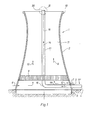
- the cooling tower 1 shown in FIG. 1 has a parabolic cooling tower shell 2 made of concrete. It stands above a water cup, generally designated 3 and embedded in the floor 4, on supports or struts 5, through the gaps of which atmospheric air can flow into the cooling tower in the direction of the arrows 6, 7. In countercurrent to the air, cooling water is rained down via internals 8. Above the internals, the exhaust air flows in the direction of arrows 9, 10 through the chimney 11 of the cooling tower 1 with considerable buoyancy because of the heating by the water to be cooled. This already creates a swath.
- a pipe 11 serves as a feed line for the exhaust gases of a furnace and can be charged with the exhaust gases of a wet separator, which is used for desulfurization of the flue gases, but can also be charged with unpurified exhaust gases via a bypass on the wet separator.
- the exhaust gases flow in the direction of arrows 12, 14 first through a horizontal branch 15 of the feed line, which is radially inserted below the internals 8 in the cooling tower, and from there via a manifold 16 into a vertical pipeline string 17, which is laid in the axis of rotation 18 of the cooling tower paraboloid.
- the cooling tower shell 2 has a crown 19 which is reinforced like a ring in the illustrated embodiment.
- the mouth 20 of the feed line 11 ', i.e. of the vertical pipe string 17 is located somewhat above the crown 19.
- the mouth 20 of the pipe string 17 is concentric with the crown 19.
- a nozzle 23 with an annular flange 24 is on the upper pipe section 21 of the tubular string 17, ie on the ring flange 22 thereof attached.
- the exhaust gas flow is accelerated in front of the mouth 25, so that it emerges at an increased speed.
- the exhaust air flow in the chimney 11, as in all other sections of the cooling tower shell 2 and its elevation 5 with the supply line 15 to 17, is kept separate from the exhaust air flow 9, 10.
- the exhaust gas flow combined in its supply line 11 ′ is closed to the outside until it reaches the mouth 20 or 25. It is released at the mouth and discharged in a concentric direct current with the exhaust air from the cooling tower rising above the chimney and the swaths carried along.
- the exhaust gas flow is accelerated to a multiple of the exit velocity of the exhaust air flow before it is released.
- the supply line 11 During operation of the power plant, the supply line 11 'receives exhaust gases from wet cleaning, which are accelerated at the mouth with the rising exhaust air flow. When the system is started up, uncleaned exhaust gas can can be discharged through the inlet 11 'via the mouth.
Landscapes
- Engineering & Computer Science (AREA)
- Mechanical Engineering (AREA)
- General Engineering & Computer Science (AREA)
- Chemical & Material Sciences (AREA)
- Combustion & Propulsion (AREA)
- Treating Waste Gases (AREA)
Abstract
Description
Die Erfindung betrifft ein Verfahren zum Abführen der Abgase von fossilen Brennstoffen, vorzugsweise von Rauchgasen mit Hilfe des Abluftstromes einer Kühlanlage, insbesondere nach Durchströmen eines Abgaswäschers mit einem Kühlturm. Außerdem betrifft die Erfindung eine Vorrichtung zur Durchführung dieses Verfahrens.The invention relates to a method for removing the exhaust gases from fossil fuels, preferably smoke gases, with the aid of the exhaust air flow from a cooling system, in particular after flowing through an exhaust gas scrubber with a cooling tower. The invention also relates to a device for carrying out this method.
Die Erfindung bezieht sich auf die Abgase von fossilen Brennstoffen, die in Prozessen entstehen, welche unter hohen Temperaturen ablaufen. Das ist der Fall z.B. bei industriellen Feuerungen vornehmlich in Kraftwerken. Diese Abgase enthalten neben relativ ungefährlichen Verbindungen eine Reihe von Schadstoffen, zu denen außer Schwefeloxyden auch Stickoxyde und Chlorverbindungen gehören. Die Ableitung dieser Gase unterliegt bei Großfeuerungsanlagen strengen Vorschriften. Dazu gehören die Kaminhöhe, die Rauchgastemperatur, die Inhaltsstoffkonzentration und die Imissionsbelastung. Die Erfindung bezieht sich daher insbesondere auf die Ableitung von Rauchgasen aus den Feuerungsanlagen von Kraftwerken, vor allem von Braunkohle- und Steinkohlekraftwerken.The invention relates to the exhaust gases from fossil fuels which arise in processes which take place at high temperatures. This is the case, for example, with industrial furnaces, primarily in power plants. These gases also contain relatively harmless compounds a number of pollutants, which include sulfur oxides, nitrogen oxides and chlorine compounds. The discharge of these gases is subject to strict regulations for large combustion plants. This includes the chimney height, the flue gas temperature, the concentration of the ingredients and the pollution level. The invention therefore relates in particular to the discharge of flue gases from the firing systems of power plants, especially lignite and hard coal power plants.
Im allgemeinen ist man bemüht, derartige Rauchgase mit entsprechend hohen Temperaturen über hohe Kamine abzuführen, um eine möglichst weitgehende Verdünnung mit der Atmosphäre zu erreichen. Die öffentlichen Diskussionen der angeblich durch den Schwefelgehalt der Rauchgase in der Atmosphäre verursachen Säurebildung (saurer Regen), hat in zunehmendem Maße zu Auflagen (Großfeuerungsanlagenverordnung, Technische Anleitung Luft) geführt, welche u.a. eine Entschwefelung der Rauchgase vorschreiben. Im allgemeinen sind die dazu bekannt gewordenen Verfahren und Rauchgaswäschen aber mit einer starken Temperaturabsenkung der Rauchgase bis zu ca. 50° C verbunden. Die die Rauchgaswäsche verlassenden gesättigten Rauchgase enthalten zudem Schwefel in einer Restkonzentration. Deswegen können sie durch Kamine nur nach vorheriger Aufheizung abgeführt werden. Schwierigkeiten bereiten auch die Verfahren, mit denen andere Schadstoffe aus den Rauchgasen entfernt werden können.In general, efforts are made to discharge such flue gases at correspondingly high temperatures via high chimneys in order to achieve the greatest possible dilution with the atmosphere. The public discussions of acid build-up (acid rain), which is said to cause the sulfur content of the flue gases in the atmosphere, have increasingly led to requirements (large combustion plant regulations, technical instructions on air) which prescribe, among other things, desulfurization of the flue gases. In general, however, the processes and flue gas washes that have become known are associated with a sharp drop in the temperature of the flue gases up to approximately 50.degree. The saturated flue gases leaving the flue gas scrub also contain sulfur in a residual concentration. Therefore, they can only be removed by fireplaces after they have been heated up. Difficulties also arise with the methods with which other pollutants can be removed from the flue gases.
In dem Bestreben, die mit der Wiederaufheizung verbundenen Kosten zu vermeiden, führt man entschwefelte kalte Rauchgase mit Temperaturen von ca. 50° C bis 70° C über Kühltürme ab. Dadurch ist es nämlich möglich, den Auftrieb der durch den Kühlprozeß aufgeheizten Abluft auszunutzen, um die eingeführten abgekühlten Rauchgase mit dem geforderten zusätzlichen Auftrieb zu versehen, wodurch eine Wiederaufheizung über investitionskostenintensive Wärmeaustauscher oder durch Dampfauskopplung mit betriebskostenintensiven Dampfwärmeaustauschern entfallen kann. Zudem erhöht sich bei der Wiederaufheizung die Menge der Rauchgasinhaltsstoffe bezogen auf die gleiche abgegebene Nutzenergie der Anlage, die in die Atmosphäre abgegeben werden muß, weil regenerative Wärmetauscher über den Schlupf ungereinigte zu den gereinigten Rauchgasen mischen; bei einer Dampfauskopplung wird der Anlagenwirkungsgrad kleiner. Bei der überwiegenden Zahl der Fälle handelt es sich um Naßkühltürme,vorzugsweise solche mit Naturzug. Im allgemeinen arbeiten solche Kühltürme nach dem sogenannten Gegenstromprinzip oder führen die Kühlluft durch das von den Einbauten abregnende Wasser im Querstrom. Oberhalb der Einbauten passiert die Abluft den Schlot des Kühlturmes. Dieser wird von der meist parabolisch gekrümmten Kühlturmschale gebildet.An der Krone solcher Kühltürme tritt die Abluft aus. Aufgrund des Wärme- und Stoffaustausches bilden sich Schwaden (gesättigte Kühlluft), die aufgrund des Phasenwechsels des Wassers latente Wärme gespeichert haben. Die große Wärmespeicherfähigkeit im Schwaden ist der Grund, warum die den thermischen Auftrieb erzeugende - durch die Temperaturdifferenz des Schwadens zur Umgebung und den Phasenwechsel des Wassers induzierte - Dichtedifferenz so lange erhalten bleibt und dafür sorgt, daß der Kühlturmschwaden größere Aufstiegshöhen als übliche Rauchgasfahnen aus Kaminen erreicht. Während nämlich die anfängliche Strömungsenergie (Impuls) schon nach einer sehr kurzen Distanz durch turbulente Reibungsvorgänge verbraucht ist, sorgen die thermischen Auftriebskräfte kontinuierlich für eine der Gravitationskraft entgegengesetzte Beschleunigung.In an effort to avoid the costs associated with reheating, desulfurized cold flue gases with temperatures of approx. 50 ° C to 70 ° C are removed via cooling towers. Thereby, it is namely possible to exploit the buoyancy of heated by the cooling process air, in order to provide the imported cooled flue gases with the required additional lift, can be omitted fwärmeaustauschern p whereby a reheating over investment cost intensive heat exchanger or by steam extraction with operating cost intensive Dam. In addition, the amount of flue gas constituents increases in relation to the same useful energy of the system that has to be released into the atmosphere when reheating, because regenerative heat exchangers mix uncleaned and cleaned flue gases via the slip; with steam extraction, the system efficiency is reduced. The vast majority of cases are wet cooling towers, preferably those with natural draft. In general, such cooling towers work according to the so-called counterflow principle or lead the cooling air in crossflow through the water that rains from the internals. Above the internals, the exhaust air passes the chimney of the cooling tower. This is formed by the mostly parabolically curved cooling tower shell, and the exhaust air escapes from the top of such cooling towers. Due to the heat and mass exchange, swaths (saturated cooling air) form, which have stored latent heat due to the phase change of the water. The large heat storage capacity in the swath is the reason why the density difference that generates the thermal buoyancy - induced by the temperature difference between the swath and the environment and the phase change of the water - is maintained for so long and ensures that the cooling tower swath reaches higher ascent heights than normal smoke gas plumes from chimneys. While the initial flow energy (impulse) is used up after a very short distance due to turbulent friction processes, the thermal buoyancy forces continuously provide an acceleration opposite to the gravitational force.
Die Erfindung bezieht sich insbesondere auf derartige Kühlanlagen. Sie geht-dabei von einem vorbekannten Verfahren aus (DE-PS 24 53 488). Im Gegensatz zu einem anderweitig bekannten Verfahren, bei dem man die Thermik der Abluft eines Kühlturmes zur Auftriebsverbesserung eingeleiteter Abgase eines Kernkraftwerkes ausnutzt und auch im Gegensatz zu einem anderen der bekannten Verfahren, mit dem man den Kühlluftdurchsatz eines Naturzugkühlturmes durch eingeleitete heiße Turbinenabgase vergrößert, werden bei dem von der Erfindung als bekannt vorausgesetzten Verfahren die naß gereinigten Gase einer Rauchgasentschwefelungsanlage nicht wie auch bekannt in einem Strom zusammengefaßt in den Kühlturm abgegeben, sondern verlassen die Abgaszuleitung im Kühlturm durch eine Mehrzahl von über den Querschnitt der Kühlturmschale oberhalb des Tropfenfangs verteilt angeordnete, mit Leitblechen bestückte Ausmündungen, mit denen eine vom praktischen Standpunkt homogene Verteilung der Abgase im Schwaden bzw. Abluft des Kühlturmes angestrebt wird.The invention relates in particular to such cooling systems. It is based on a previously known method (DE-PS 24 53 488). In contrast to an otherwise known methods, in which the thermal exhaust air of a cooling tower to Auftriebsverbesserun g initiated exhaust gases utilizing a nuclear power plant, and also in contrast to another of the known methods with which one of the cooling air throughput of a Naturzugkühlturmes by introduced hot turbine exhaust gases enlarged, in the process assumed to be known by the invention, the wet cleaned gases of a flue gas desulfurization system are not, as is also known, discharged into a stream into the cooling tower, but instead leave the exhaust gas supply line in the cooling tower through a plurality of distributed over the cross section of the cooling tower shell above the drip catcher Baffles equipped with openings, with which a homogeneous from a practical point of view Distribution of the exhaust gases in the steam or exhaust air of the cooling tower is sought.
Die mit diesem bekannten Verfahren angestrebte Energieeinsparungdurch den Fortfall der Wiederaufheizung der Rauchgase nach ihrer Abkühlung in der Entschwefelungsanlage hat sich in einem Modellkraftwerk (Völklingen) realisieren lassen. Die Vorstellungen aber, die man sich über die Einflüsse dieses Verfahrens auf den näheren Umkreis des Kühlturmes bzw. des Kraftwerkes gemacht hat, haben sich nicht in dem notwendigen Umfang bestätigt. Während man nämlich davon ausging, daß die infolge ihrer vorausgehenden Naßreinigung in der Entschwefelungsanlage relativ sauberen Abgase mit dem Ziel einer kleineren Imissionsbelastung besser mit dem Kühlturmschwaden als über den Kamin in die Atmosphäre abgeleitet werden können, hat sich ergeben, daß Säureschäden in der Umgebung des Kühlturms auftreten. Das führt u.a. zum Abrosten von Stahlteilen und verlangt auch überdachte Parkplätze, um schwere Schäden von den Fahrzeugen abzuwenden.The energy saving aimed at with this known method by eliminating the reheating of the flue gases after they have cooled down in the desulfurization system has been realized in a model power plant (Völklingen). However, the ideas that have been made about the effects of this process on the immediate vicinity of the cooling tower or the power plant have not been confirmed to the extent necessary. While it was assumed that the exhaust gases, which were relatively clean as a result of their previous wet cleaning in the desulfurization plant, with the aim of lower emission pollution, can be better discharged into the atmosphere with the cooling tower vapor than through the chimney, it has been found that acid damage in the vicinity of the cooling tower occur. This leads among other things for rusting steel parts and also requires covered parking spaces to prevent serious damage to the vehicles.
Ursache hierfür ist, daß die bei dem vorbekannten Verfahren auftretende homogene Durchmischung der Inhaltsstoffe von den naß gereinigten Rauchgasen (insbesondere sind dies die Restkonzentrationen von Schwefelverbindungen) mit dem Schwaden überall innerhalb des Schwadens zur Bildung von (schwefliger oder auch Schwefel-)Säure führt. Diese Säurebildung ist nicht etwa eine homogene Reaktion, sondern findet auf den durch mitgeführte Keime ausgelösten Sekundärkondensationen und auf den Oberflächen der Sprühtropfen statt. Eine solche chemische Umwandlung ist nur innerhalb einer sehr kleinen Grenzkonzentration noch von dem Konzentrationsgefälle abhängig, die jedoch trotz Rauchgasreinigung und homogener Vermischung der naß gereinigten Abgase mit der Abluft des Kühlturms in der Regel überschritten wird. Oberhalb dieser Grenzkonzentration ist die chemische Umwandlung unabhängig von der Menge der für die Reaktion verfügbaren Schadstoffe. Deshalb findet bei dem vorbekannten Verfahren im gesamten Schwadenbereich eine maximale Umsetzung statt, die über Sprühverluste und Sekundärkondensationen im Nahbereich des Kühlturms ausfällt und für die beschriebenen Schäden verantwortlich ist.The reason for this is that the homogeneous mixing of the ingredients from the wet-cleaned flue gases (in particular these are the residual concentrations of sulfur compounds) with the steam, which occurs in the known process, leads to the formation of (sulfurous or also sulfuric) acid anywhere in the steam. This acid formation is not a homogeneous reaction, but takes place on the secondary condens caused by the germs carried along sations and on the surfaces of the spray drops. Such a chemical conversion is only dependent on the concentration gradient within a very small limit concentration, which, however, is generally exceeded despite flue gas cleaning and homogeneous mixing of the wet cleaned exhaust gases with the exhaust air from the cooling tower. Above this limit concentration, the chemical conversion is independent of the amount of pollutants available for the reaction. Therefore, in the previously known method, there is a maximum conversion in the entire swath area, which fails due to spray losses and secondary condensation in the vicinity of the cooling tower and is responsible for the damage described.
Der Erfindung liegt die Aufgabe zugrunde, einerseits die mit dem bekannten Verfahren-erreichte Energieeinsparung durch den Fortfall der Wiederaufheizung der Rauchgase nach ihrer Abkühlung beizubehalten, andererseits aber das Verfahren so zu führen, daß die Imissionsbelastung im Nahbereich des Kühlturmes bzw. des Kraftwerkes verringert wird.The invention has for its object, on the one hand, to maintain the energy saving achieved with the known method by eliminating the reheating of the flue gases after their cooling, but on the other hand to carry out the method in such a way that the emission load in the vicinity of the cooling tower or the power plant is reduced.
Diese Aufgabe löst die Erfindung mit den kennzeichnenden Merkmalen des Anspruches 1. Zweckmäßige Ausführungsformen der Erfindung sind Gegenstand ihrer Unteransprüche.The invention solves this problem with the characterizing features of
Die Erfindung hat den Vorteil, daß alle Beeinträchtigungen durch Säurebildung im Kühlturm entfallen und dementsprechend insbesondere die Kühlturmeinbauten geschützt werden. Außerhalb des Kühlturmes verhalten sich die Kühlturmschwaden trotz der gemeinsam mit ihnen emittierten Rauchgase weitgehend so wie die Kühlturmschwaden von Anlagen, bei denen die Rauchgase über Kamine abgeleitet werden, die in der Regel ebenfalls mit den Kühlturmschwaden in Kontakt geraten. Allerdings ergibt sich bei dem erfindungsgemäßen Verfahren demgegenüber die Einsparung an Energie durch die notwendige Wiederaufheizun'g der abgekühlten Abgase. Wegen der bei 100° C bis 150° C liegenden Abgastemperaturen für die Kaminabführung ist diese Einsparung sehr erheblich.The invention has the advantage that all impairments due to acid formation in the cooling tower are eliminated, and accordingly in particular the cooling tower internals to be protected. Outside the cooling tower, despite the smoke gases emitted together with them, the cooling tower swaths behave largely like the cooling tower swaths of systems in which the smoke gases are discharged via chimneys, which usually also come into contact with the cooling tower swaths. In contrast, in the method according to the invention, the saving in energy results from the necessary reheating of the cooled exhaust gases. This saving is very significant because of the exhaust gas temperatures for the chimney discharge at 100 ° C to 150 ° C.
Bei dem erfindungsgemäßen Verfahren findet infolge der thermischen Turbulenzen oberhalb der Kühlturmzone eine Vermischung der Abgase mit dem Schwaden statt, die dazu führt, daß bei dem erfindungsgemäßen Verfah- .ren in einem Abstand von etwa fünf Kühldurchmessern, das sind bei üblichen Kraftwerken z.B. 500 m Abstand, eine homogene Verteilung der Rauchgase mit den Kühlturmschwaden stattfindet.In the method according to the invention, due to the thermal turbulence above the cooling tower zone, the exhaust gases are mixed with the steam, which means that in the method according to the invention at a distance of about five cooling diameters, that is, in conventional power plants, e.g. 500 m distance, a homogeneous distribution of the flue gases with the cooling tower swaths takes place.
Üblicherweise werden die Sprühtropfen und Sekundärkondensationen bis zu 1,5 km weit getragen. Innerhalb eines Kreises mit einem diesen Abständen entsprechenden Radius um den Kühlturm wird demnach durch das erfindungsgemäße Verfahren das Imissionsverhalten verbessert.The spray drops and secondary condensations are usually carried up to 1.5 km away. The emission behavior is accordingly improved within a circle with a radius corresponding to these distances around the cooling tower.
Von besonderer Bedeutung ist das erfindungsgemäße Verfahren für solche Kraftwerke, welche ihre Rauchgase nicht nur entschwefeln, sondern auch andere Schadstoffe, darunter vor allem die Stickoxyde entfernen, bevor die Abgase emittiert werden.The method according to the invention is of particular importance for power plants which not only desulfurize their flue gases, but also others Remove pollutants, especially the nitrogen oxides, before the exhaust gases are emitted.
Durch die Reduzierung der salpetersäurebildenden NO bzw. N02-Moleküle werden weniger OH-Radikale als zuvor gebunden und stehen für die Bildung von Schwefelsäure oder schwefliger Säure vermehrt zur Verfügung. Gerade für diesen Anwendungsfall ist es wichtig, die Stoffströme durch das erfindungsgemäße Verfahren zu trennen.By reducing the nitric acid-forming NO or NO 2 molecules, fewer OH radicals are bound than before and are increasingly available for the formation of sulfuric acid or sulfurous acid. For this particular application, it is important to separate the material flows using the method according to the invention.
Mit den Merkmalen des Anspruches 2 wird erreicht, daß die Vermischung der Abgase mit den Kühlturmschwaden verzögert und sich dadurch im Ergebnis der Kreis vergrößern läßt, in dem das Emissionsverhalten um den Kühlturm verbessert wird. Der für diese Ausführungsform des Verfahrens erforderliche bauliche Aufwand ist relativ gering.With the features of
Die Verwirklichung der Merkmale des Anspruches 3 bietet den Vorteil, daß man die Zuleitung der Abgase in den Kühlturm einbauen kann.The realization of the features of
Mit dem Merkmal des Anspruches 4 läßt sich eine weitere Eigenschaft des erfindungsgemäßen Verfahrens vorteilhaft nutzen.With the feature of
Während man bei dem bekannten Verfahren bei Ausfall der Rauchgasreinigung in der Regel gezwungen ist, das im By-pass zu den Naßwäschern geführte Abgas über einen Notkamin abzuführen, ermöglicht die Erfindung die Weiterbenutzung der Zuleitung zum Kühlturm, weil das heiße und mit allen Schadstoffen beladene Abgas der Anlage den Kühlturm nicht beeinträchtigen kann.While in the known method in the event of failure of the flue gas cleaning system, as a rule, the exhaust gas led in the bypass to the wet scrubbers is forced to be discharged via an emergency chimney, the invention enables the supply line to be used further Cooling tower, because the hot exhaust gas from the system, which is loaded with all pollutants, cannot impair the cooling tower.
Ähnliches gilt auch für das An- und Abfahren der Anlage und auch für alle anderen Betriebszustände, bei denen der Kühlturm unter Teillast gefahren wird (z.B. Wärmeauskopplung - Heizkraftwerksbetrieb). Bei verminderter oder fehlender Schwadenbildung im Kühlturm ermöglicht die Erfindung ebenfalls eine Weiterbenutzung der Anlage ohne Notkamine oder sonstige Hilfseinrichtungen, da im Gegensatz zu dem bekannten Verfahren mit homogener Vermischung eine definierte Rauchgasführung bis zur Kühlturmkrone existiert und die Rauchgase hier mit hohen Geschwindigkeiten emittiert werden können.The same applies to the start-up and shutdown of the system and also to all other operating states in which the cooling tower is operated under partial load (e.g. heat extraction - heating plant operation). In the case of reduced or no steam formation in the cooling tower, the invention also enables the system to be used without emergency chimneys or other auxiliary devices, since, in contrast to the known method with homogeneous mixing, a defined flue gas flow to the top of the cooling tower exists and the flue gases can be emitted here at high speeds.
Wenn man die Abgase aus der Zuleitung konzentrisch in den Abluftstrom einführt, ergibt sich eine Verminderung der Menge des Schwadens, der mit dem Abgasstrom in Berührung kommt. Das führt dazu, daß im Kern des Abluftstromes keine Sekundärkondensationen stattfinden und die Schadstoffimmission auf den Mantel des Abgasstromes in den niedrigen Luftschichten beschränkt bleibt. Da der Abgasstrom erst im Bereich der Kühlturmkrone, d.h. unterhalb oder kurz oberhalb des oberen Kühlturmendes eingeführt wird, ergibt sich der für die Beschleunigung der Rauchgase in höhere Luftschichten erforderliche Energieaustausch. Da der Abluftstrom in dem Schlot, d.h. unterhalb der Einmündung der Rauchgase in den Abluftstrom bzw. den Schwaden getrennt von dem Abgasstrom gehalten wird, bildet sich innerhalb der Kühlturmschale die übliche Strömung aus, welche frei von den bei dem bekannten Verfahren durch die Einführung des Abgasstromes in den Kühlturm erzeugten Wirbeln ist. Dadurch stellt sich die angestrebte bessere Zugwirkung des Kühlturms auf natürliche Weise ein.If the exhaust gases from the supply line are introduced concentrically into the exhaust air stream, there is a reduction in the amount of steam that comes into contact with the exhaust gas stream. This means that no secondary condensation takes place in the core of the exhaust air flow and that the pollutant emissions remain limited to the jacket of the exhaust gas flow in the low air layers. Since the exhaust gas flow is only introduced in the area of the cooling tower crown, ie below or just above the upper end of the cooling tower, the energy exchange required to accelerate the flue gases into higher air layers results. Since the exhaust air flow in the chimney, ie below the confluence of the flue gases in the exhaust air flow or the swaths, is separate from the exhaust gas flow ten, the usual flow forms inside the cooling tower shell, which is free of the vortices generated in the known method by the introduction of the exhaust gas stream into the cooling tower. As a result, the desired better pulling action of the cooling tower occurs naturally.
Die Einzelheiten, weiteren Merkmale und andere Vorteile der Erfindung ergeben sich aus der nachfolgenden Beschreibung des Erfindungsgegenstandes anhand der Figuren in der Zeichnung; es zeigen
- Fig. 1 schematisch und unter Fortlassung aller für das Verständnis der Erfindung nicht erforderlicher Einzelheiten einen Naturzugkühlturm im Längsschnitt und die damit verbundenen Teile der erfindungsgemäßen Anlage,
- Fig. 2 eine Draufsicht auf den Gegenstand der Fig. 1 und
- Fig. 3 eine Einzelheit, die mit III in Fig. 1 gekennzeichnet ist.
- 1 schematically and omitting all details not necessary for understanding the invention, a natural draft cooling tower in longitudinal section and the associated parts of the system according to the invention,
- Fig. 2 is a plan view of the subject of Fig. 1 and
- Fig. 3 shows a detail, which is marked with III in Fig. 1.
Der in Fig. l dargestellte Kühlturm 1 hat eine parabolische Kühlturmschale 2 aus Beton. Er steht über einer allgemein mit 3 bezeichneten und in den Boden 4 eingelassenen Wassertasse auf Stützen oder Streben 5, durch deren Zwischenräume atmosphärische Luft in Richtung der Pfeile 6, 7 in den Kühlturm einströmen kann. Im Gegenstrom zu der Luft wird Kühlwasser über Einbauten 8 abgeregnet. Oberhalb der Einbauten strömt die Abluft in Richtung der Pfeile 9, 10 durch den Schlot 11 des Kühlturms 1 mit erheblichem Auftrieb wegen der Aufheizung durch das zu kühlende Wasser ab. Hierbei tritt bereits eine Schwadenbildung ein.The
Eine Rohrleitung 11' dient als Zuleitung für Abgase einer Feuerung und kann sowohl mit den Abgasen eines Naßabscheiders beaufschlagt werden, der zur Entschwefelung der Rauchgase dient, läßt sich aber auch über einen By-pass am Naßabscheider mit ungereinigten Abgasen beaufschlagen. Die Abgase strömen in Richtung der Pfeile 12, 14 zunächst durch einen waagerechten, unterhalb der Einbauten 8 im Kühlturm radial eingeführten Zweig 15 der Zuleitung und von dort über einen Krümmer 16 in einen senkrechten Rohrleitungsstrang 17, der in der Rotationsachse 18 des Kühlturmparaboloides verlegt ist.A pipe 11 'serves as a feed line for the exhaust gases of a furnace and can be charged with the exhaust gases of a wet separator, which is used for desulfurization of the flue gases, but can also be charged with unpurified exhaust gases via a bypass on the wet separator. The exhaust gases flow in the direction of
Die Kühlturmschale 2 hat eine Krone 19, die bei dem dargestellten Ausführungsbeispiel ringartig verstärkt ist. Die Mündung 20 der Zuleitung 11', d.h. des senkrechten Rohrstranges 17 liegt etwas oberhalb der Krone 19.The
Wie die Darstellung der Fig. 2 erkennen läßt, liegt die Mündung 20 des Rohrstranges 17 konzentrisch zu der Krone 19.As can be seen from the illustration in FIG. 2, the
Gemäß der Darstellung der Fig. 3 ist an den oberen Rohrschuß 21 des Rohrstranges 17, d.h. an dessen Ringflansch 22 eine Düse 23 mit einem Ringflansch 24 befestigt. Mit der Düse 23 wird der Abgasstrom vor der Mündung 25 beschleunigt, so daß er mit erhöhter Geschwindigkeit austritt.According to the illustration in FIG. 3, a nozzle 23 with an
Im Betrieb wird der Abluftstrom in dem Schlot 11 wie auch in allen anderen Abschnitten der Kühlturmschale 2 und ihrer Aufständerung 5 mit der Zuleitung 15 bis 17 getrennt von dem Abluftstrom 9, 10 gehalten. Andererseits ist der in seiner Zuleitung 11' zusammengefaßte Abgasstrom nach außen abgeschlossen, bis er die Mündung 20 bzw. 25 erreicht. An der Mündung wird er freigegeben und in einem konzentrischen Gleichstrom mit der über dem Schlot aufsteigenden Abluft des Kühlturms und den mitgeführten Schwaden abgeführt.In operation, the exhaust air flow in the
Benutzt man die Düse nach Fig.3, so wird der Abgasstrom auf ein Mehrfaches der Austrittsgeschwindigkeit des Abluftstromes beschleunigt, bevor er freigegeben wird.If the nozzle according to FIG. 3 is used, the exhaust gas flow is accelerated to a multiple of the exit velocity of the exhaust air flow before it is released.
Die konzentrische Führung des Abgasstromes mit dem Rohrstrang 17 im Schlot 11 des Kühlturmes 1, die in Fig. 1 wiedergegeben ist, ermöglicht eine günstige Unterbringung der Zuleitung 11', nämlich innerhalb der Kühlturmschale 2 und eine geradlinige Rohrführung bis zur Mündung 20 bzw. 25.The concentric routing of the exhaust gas stream with the
Im Betrieb des Kraftwerkes nimmt die Zuleitung 11' Abgase aus der Naßreinigung auf, die an der Mündung mit dem aufsteigenden Abluftstrom beschleunigt werden. Beim Anfahren der Anlage kann ungereingtes Abgas durch die Zuleitung 11' über die Mündung abgeführt werden.During operation of the power plant, the supply line 11 'receives exhaust gases from wet cleaning, which are accelerated at the mouth with the rising exhaust air flow. When the system is started up, uncleaned exhaust gas can can be discharged through the inlet 11 'via the mouth.
Claims (6)
Priority Applications (1)
| Application Number | Priority Date | Filing Date | Title |
|---|---|---|---|
| AT84104682T ATE38088T1 (en) | 1984-03-02 | 1984-04-26 | METHOD AND PLANT FOR REMOVING THE EXHAUST GASES OF FOSSIL FUELS, PREFERABLY FLUE GASES, USING THE AIR STREAM OF A REFRIGERATION PLANT, ESPECIALLY AFTER PASSING A WET SEPARATOR WITH A COOLING TOWER. |
Applications Claiming Priority (2)
| Application Number | Priority Date | Filing Date | Title |
|---|---|---|---|
| DE3407705 | 1984-03-02 | ||
| DE3407705 | 1984-03-02 |
Publications (3)
| Publication Number | Publication Date |
|---|---|
| EP0155340A2 true EP0155340A2 (en) | 1985-09-25 |
| EP0155340A3 EP0155340A3 (en) | 1986-02-05 |
| EP0155340B1 EP0155340B1 (en) | 1988-10-19 |
Family
ID=6229393
Family Applications (1)
| Application Number | Title | Priority Date | Filing Date |
|---|---|---|---|
| EP84104682A Expired EP0155340B1 (en) | 1984-03-02 | 1984-04-26 | Method and installation for evacuating exhaust gases from fossil fuels, preferably flue gas, especially after passing through a wet scrubber, using the exhaust air flow from a cooling plant, especially from a cooling tower |
Country Status (3)
| Country | Link |
|---|---|
| EP (1) | EP0155340B1 (en) |
| AT (1) | ATE38088T1 (en) |
| DE (1) | DE3474713D1 (en) |
Cited By (4)
| Publication number | Priority date | Publication date | Assignee | Title |
|---|---|---|---|---|
| WO1986005577A1 (en) * | 1985-03-16 | 1986-09-25 | Saarbergwerke Aktiengesellschaft | Smoke gas exhaust by way of a cooling tower |
| WO1995033966A1 (en) * | 1994-06-07 | 1995-12-14 | Veag Vereinigte Energiewerke Ag | Device for incorporating the purified-gas ducts from a fossil-fuel power station desulphurization plant in a natural-convection wet cooling power |
| WO2008056836A1 (en) | 2006-11-07 | 2008-05-15 | Lg Electronics Inc. | Device of supplying water for laundry dryer and method for controlling the same |
| CN102401581A (en) * | 2011-07-27 | 2012-04-04 | 中国电力工程顾问集团西北电力设计院 | Mixed ventilation indirect cooling tower system and cooling method thereof |
Family Cites Families (2)
| Publication number | Priority date | Publication date | Assignee | Title |
|---|---|---|---|---|
| DE1601137A1 (en) * | 1967-10-31 | 1970-05-06 | Maschb Ag | A self-ventilating cooling unit and a chimney for industrial plants, especially power plants |
| DE1941193A1 (en) * | 1969-08-13 | 1971-03-11 | Plein Wagner Soehne | Chimney head with attached nozzle |
-
1984
- 1984-04-26 DE DE8484104682T patent/DE3474713D1/en not_active Expired
- 1984-04-26 EP EP84104682A patent/EP0155340B1/en not_active Expired
- 1984-04-26 AT AT84104682T patent/ATE38088T1/en not_active IP Right Cessation
Cited By (10)
| Publication number | Priority date | Publication date | Assignee | Title |
|---|---|---|---|---|
| WO1986005577A1 (en) * | 1985-03-16 | 1986-09-25 | Saarbergwerke Aktiengesellschaft | Smoke gas exhaust by way of a cooling tower |
| US4784810A (en) * | 1985-03-16 | 1988-11-15 | Saarbergwerke Aktiengesellschaft | Smoke gas exhaust by way of a cooling tower |
| US4885011A (en) * | 1985-03-16 | 1989-12-05 | Saarbergwerke Aktiengesellschaft | Cooling tower for the cooling water that drains/ from the condensor of a steam generator or the condensors/ of a plurality of steam generators |
| WO1995033966A1 (en) * | 1994-06-07 | 1995-12-14 | Veag Vereinigte Energiewerke Ag | Device for incorporating the purified-gas ducts from a fossil-fuel power station desulphurization plant in a natural-convection wet cooling power |
| AU684186B2 (en) * | 1994-06-07 | 1997-12-04 | Balcke-Durr Energietechnik Gmbh | Device for incorporating the purified-gas ducts from a fossil-fuel power station desulphurization plant in natural-convection wet cooling power |
| WO2008056836A1 (en) | 2006-11-07 | 2008-05-15 | Lg Electronics Inc. | Device of supplying water for laundry dryer and method for controlling the same |
| EP2092106A4 (en) * | 2006-11-07 | 2011-04-06 | Lg Electronics Inc | Device of supplying water for laundry dryer and method for controlling the same |
| US8250777B2 (en) | 2006-11-07 | 2012-08-28 | Lg Electronics Inc. | Device of supplying water for laundry dryer and method for controlling the same |
| CN102401581A (en) * | 2011-07-27 | 2012-04-04 | 中国电力工程顾问集团西北电力设计院 | Mixed ventilation indirect cooling tower system and cooling method thereof |
| CN102401581B (en) * | 2011-07-27 | 2013-05-08 | 中国电力工程顾问集团西北电力设计院 | Mixed ventilation indirect cooling tower system and cooling method thereof |
Also Published As
| Publication number | Publication date |
|---|---|
| ATE38088T1 (en) | 1988-11-15 |
| EP0155340A3 (en) | 1986-02-05 |
| DE3474713D1 (en) | 1988-11-24 |
| EP0155340B1 (en) | 1988-10-19 |
Similar Documents
| Publication | Publication Date | Title |
|---|---|---|
| DE60205274T2 (en) | METHOD AND APPARATUS FOR GAS WASHING USING GUIDELINES | |
| DE69205161T2 (en) | PULSATING ATMOSPHERIC FLUID BED COMBUSTION PLANT AND METHOD. | |
| DE69704953T2 (en) | METHOD AND COMBUSTION APPARATUS WITH A DEVICE FOR INJECTING A NOx REDUCER | |
| DE68907116T2 (en) | Process for reducing the content of non-condensable elements which are contained in and are soluble in flue gases containing condensable elements. | |
| DE69201587T2 (en) | Scrubber for multiple gases. | |
| DE69006017T2 (en) | DEVICE AND METHOD FOR ELIMINATING AIR POLLUTION. | |
| EP0616022B1 (en) | Process for pressure gasification of fine particulate fuels | |
| EP0132584A2 (en) | Method and installation for reducing the emission of noxious matter in the flue gases of combustion plants | |
| EP0155340B1 (en) | Method and installation for evacuating exhaust gases from fossil fuels, preferably flue gas, especially after passing through a wet scrubber, using the exhaust air flow from a cooling plant, especially from a cooling tower | |
| EP0089036B1 (en) | Method of purifying exhaust gases and for the recuperation of heat, and device for carrying out this method | |
| DE3604946C2 (en) | Method and device for cleaning flue gases | |
| DE68906228T2 (en) | METHOD FOR GENERATING HEAT WITH DESULFURATION OF EXHAUST GASES BY ABSORBENT PARTICLES IN FINE PARTICLE SIZES IN A HIKING BED. | |
| DE69406778T2 (en) | METHOD AND DEVICE FOR THE PURIFICATION OF HOT GAS AND THE EXTRACTION OF ENERGY FROM THE SAME | |
| AT517338B1 (en) | Flue gas heat exchanger and method for operating a flue gas heat exchanger | |
| DE29621346U1 (en) | Exhaust gas treatment device | |
| EP0107144B1 (en) | Process for the removal of air contaminants from waste gases, especially from flue gases, by condensation | |
| DE69100523T2 (en) | Method and device for generating heat with desulfurization of exhaust gases by means of fine particle size absorbent particles in a moving bed. | |
| DE69309636T2 (en) | Device and method for the thermal destruction of acidic substances in flue gases | |
| DE2931773A1 (en) | SYSTEM FOR REDUCING THE SULFUR DIOXIDE CONTENT | |
| DE69931924T2 (en) | METHOD FOR CLEANING EXHAUST GAS | |
| DE3329342C2 (en) | Process for the treatment of flue gases from a steam generating plant | |
| DE2844274A1 (en) | Double adsorption to remove pollutants from exhaust gases - having initial bed to remove sulphur tri:oxide followed by cooling and adsorption to remove the rest giving reduced corrosion | |
| DD275725A1 (en) | METHOD AND SYSTEM FOR SMOKE-GAS SINKING | |
| DE3040078C2 (en) | Process for the desulphurization of exhaust gases from liquid fuels | |
| DE3533199A1 (en) | METHOD AND SYSTEM FOR PURIFYING THE EXHAUST GAS FROM COMBUSTION SYSTEMS |
Legal Events
| Date | Code | Title | Description |
|---|---|---|---|
| PUAI | Public reference made under article 153(3) epc to a published international application that has entered the european phase |
Free format text: ORIGINAL CODE: 0009012 |
|
| AK | Designated contracting states |
Designated state(s): AT BE CH DE FR GB IT LI LU NL SE |
|
| PUAL | Search report despatched |
Free format text: ORIGINAL CODE: 0009013 |
|
| AK | Designated contracting states |
Designated state(s): AT BE CH DE FR GB IT LI LU NL SE |
|
| 17P | Request for examination filed |
Effective date: 19860731 |
|
| 17Q | First examination report despatched |
Effective date: 19870324 |
|
| GRAA | (expected) grant |
Free format text: ORIGINAL CODE: 0009210 |
|
| AK | Designated contracting states |
Kind code of ref document: B1 Designated state(s): AT BE CH DE FR GB IT LI LU NL SE |
|
| PG25 | Lapsed in a contracting state [announced via postgrant information from national office to epo] |
Ref country code: SE Effective date: 19881019 Ref country code: IT Free format text: LAPSE BECAUSE OF FAILURE TO SUBMIT A TRANSLATION OF THE DESCRIPTION OR TO PAY THE FEE WITHIN THE PRESCRIBED TIME-LIMIT;WARNING: LAPSES OF ITALIAN PATENTS WITH EFFECTIVE DATE BEFORE 2007 MAY HAVE OCCURRED AT ANY TIME BEFORE 2007. THE CORRECT EFFECTIVE DATE MAY BE DIFFERENT FROM THE ONE RECORDED. Effective date: 19881019 |
|
| REF | Corresponds to: |
Ref document number: 38088 Country of ref document: AT Date of ref document: 19881115 Kind code of ref document: T |
|
| REF | Corresponds to: |
Ref document number: 3474713 Country of ref document: DE Date of ref document: 19881124 |
|
| ET | Fr: translation filed | ||
| GBT | Gb: translation of ep patent filed (gb section 77(6)(a)/1977) | ||
| PG25 | Lapsed in a contracting state [announced via postgrant information from national office to epo] |
Ref country code: AT Effective date: 19890426 |
|
| PG25 | Lapsed in a contracting state [announced via postgrant information from national office to epo] |
Ref country code: LU Free format text: LAPSE BECAUSE OF NON-PAYMENT OF DUE FEES Effective date: 19890430 Ref country code: LI Effective date: 19890430 Ref country code: CH Effective date: 19890430 |
|
| PLBE | No opposition filed within time limit |
Free format text: ORIGINAL CODE: 0009261 |
|
| STAA | Information on the status of an ep patent application or granted ep patent |
Free format text: STATUS: NO OPPOSITION FILED WITHIN TIME LIMIT |
|
| 26N | No opposition filed | ||
| REG | Reference to a national code |
Ref country code: CH Ref legal event code: PL |
|
| PGFP | Annual fee paid to national office [announced via postgrant information from national office to epo] |
Ref country code: NL Payment date: 19910430 Year of fee payment: 8 |
|
| PG25 | Lapsed in a contracting state [announced via postgrant information from national office to epo] |
Ref country code: NL Effective date: 19921101 |
|
| NLV4 | Nl: lapsed or anulled due to non-payment of the annual fee | ||
| PGFP | Annual fee paid to national office [announced via postgrant information from national office to epo] |
Ref country code: GB Payment date: 19930413 Year of fee payment: 10 |
|
| PGFP | Annual fee paid to national office [announced via postgrant information from national office to epo] |
Ref country code: FR Payment date: 19930417 Year of fee payment: 10 |
|
| PG25 | Lapsed in a contracting state [announced via postgrant information from national office to epo] |
Ref country code: GB Effective date: 19940426 |
|
| PGFP | Annual fee paid to national office [announced via postgrant information from national office to epo] |
Ref country code: BE Payment date: 19940506 Year of fee payment: 11 |
|
| GBPC | Gb: european patent ceased through non-payment of renewal fee |
Effective date: 19940426 |
|
| PG25 | Lapsed in a contracting state [announced via postgrant information from national office to epo] |
Ref country code: FR Effective date: 19941229 |
|
| REG | Reference to a national code |
Ref country code: FR Ref legal event code: ST |
|
| PG25 | Lapsed in a contracting state [announced via postgrant information from national office to epo] |
Ref country code: BE Effective date: 19950430 |
|
| BERE | Be: lapsed |
Owner name: S.A. HAMON-SOBELCO Effective date: 19950430 |
|
| PGFP | Annual fee paid to national office [announced via postgrant information from national office to epo] |
Ref country code: DE Payment date: 19970625 Year of fee payment: 14 |
|
| PG25 | Lapsed in a contracting state [announced via postgrant information from national office to epo] |
Ref country code: DE Free format text: LAPSE BECAUSE OF NON-PAYMENT OF DUE FEES Effective date: 19990202 |