EP0155340A2 - Procédé et installation d'évacuation des gaz perdus des combustibles fossiles, de préférence des fumées, en particulier àprès passage dans un séparateur par voie humide, à l'aide du courant d'air d'échappement d'une installation de refroidissement, en particulier d'une tour de refroidissement - Google Patents
Procédé et installation d'évacuation des gaz perdus des combustibles fossiles, de préférence des fumées, en particulier àprès passage dans un séparateur par voie humide, à l'aide du courant d'air d'échappement d'une installation de refroidissement, en particulier d'une tour de refroidissement Download PDFInfo
- Publication number
- EP0155340A2 EP0155340A2 EP84104682A EP84104682A EP0155340A2 EP 0155340 A2 EP0155340 A2 EP 0155340A2 EP 84104682 A EP84104682 A EP 84104682A EP 84104682 A EP84104682 A EP 84104682A EP 0155340 A2 EP0155340 A2 EP 0155340A2
- Authority
- EP
- European Patent Office
- Prior art keywords
- exhaust
- cooling tower
- exhaust gas
- exhaust air
- gases
- Prior art date
- Legal status (The legal status is an assumption and is not a legal conclusion. Google has not performed a legal analysis and makes no representation as to the accuracy of the status listed.)
- Granted
Links
Images

Classifications
-
- F—MECHANICAL ENGINEERING; LIGHTING; HEATING; WEAPONS; BLASTING
- F23—COMBUSTION APPARATUS; COMBUSTION PROCESSES
- F23L—SUPPLYING AIR OR NON-COMBUSTIBLE LIQUIDS OR GASES TO COMBUSTION APPARATUS IN GENERAL ; VALVES OR DAMPERS SPECIALLY ADAPTED FOR CONTROLLING AIR SUPPLY OR DRAUGHT IN COMBUSTION APPARATUS; INDUCING DRAUGHT IN COMBUSTION APPARATUS; TOPS FOR CHIMNEYS OR VENTILATING SHAFTS; TERMINALS FOR FLUES
- F23L17/00—Inducing draught; Tops for chimneys or ventilating shafts; Terminals for flues
-
- F—MECHANICAL ENGINEERING; LIGHTING; HEATING; WEAPONS; BLASTING
- F28—HEAT EXCHANGE IN GENERAL
- F28C—HEAT-EXCHANGE APPARATUS, NOT PROVIDED FOR IN ANOTHER SUBCLASS, IN WHICH THE HEAT-EXCHANGE MEDIA COME INTO DIRECT CONTACT WITHOUT CHEMICAL INTERACTION
- F28C1/00—Direct-contact trickle coolers, e.g. cooling towers
- F28C1/003—Direct-contact trickle coolers, e.g. cooling towers comprising outlet ducts for exhaust gases
-
- Y—GENERAL TAGGING OF NEW TECHNOLOGICAL DEVELOPMENTS; GENERAL TAGGING OF CROSS-SECTIONAL TECHNOLOGIES SPANNING OVER SEVERAL SECTIONS OF THE IPC; TECHNICAL SUBJECTS COVERED BY FORMER USPC CROSS-REFERENCE ART COLLECTIONS [XRACs] AND DIGESTS
- Y02—TECHNOLOGIES OR APPLICATIONS FOR MITIGATION OR ADAPTATION AGAINST CLIMATE CHANGE
- Y02B—CLIMATE CHANGE MITIGATION TECHNOLOGIES RELATED TO BUILDINGS, e.g. HOUSING, HOUSE APPLIANCES OR RELATED END-USER APPLICATIONS
- Y02B30/00—Energy efficient heating, ventilation or air conditioning [HVAC]
- Y02B30/70—Efficient control or regulation technologies, e.g. for control of refrigerant flow, motor or heating
Definitions
- the invention relates to a method for removing the exhaust gases from fossil fuels, preferably smoke gases, with the aid of the exhaust air flow from a cooling system, in particular after flowing through an exhaust gas scrubber with a cooling tower.
- the invention also relates to a device for carrying out this method.
- the invention relates to the exhaust gases from fossil fuels which arise in processes which take place at high temperatures. This is the case, for example, with industrial furnaces, primarily in power plants. These gases also contain relatively harmless compounds a number of pollutants, which include sulfur oxides, nitrogen oxides and chlorine compounds. The discharge of these gases is subject to strict regulations for large combustion plants. This includes the chimney height, the flue gas temperature, the concentration of the ingredients and the pollution level.
- the invention therefore relates in particular to the discharge of flue gases from the firing systems of power plants, especially lignite and hard coal power plants.
- the large heat storage capacity in the swath is the reason why the density difference that generates the thermal buoyancy - induced by the temperature difference between the swath and the environment and the phase change of the water - is maintained for so long and ensures that the cooling tower swath reaches higher ascent heights than normal smoke gas plumes from chimneys. While the initial flow energy (impulse) is used up after a very short distance due to turbulent friction processes, the thermal buoyancy forces continuously provide an acceleration opposite to the gravitational force.
- the invention relates in particular to such cooling systems. It is based on a previously known method (DE-PS 24 53 488).
- a previously known method in which the thermal exhaust air of a cooling tower to Auftriebsverêtun g initiated exhaust gases utilizing a nuclear power plant, and also in contrast to another of the known methods with which one of the cooling air throughput of a Naturzugkühlturmes by introduced hot turbine exhaust gases enlarged, in the process assumed to be known by the invention, the wet cleaned gases of a flue gas desulfurization system are not, as is also known, discharged into a stream into the cooling tower, but instead leave the exhaust gas supply line in the cooling tower through a plurality of distributed over the cross section of the cooling tower shell above the drip catcher Baffles equipped with openings, with which a homogeneous from a practical point of view Distribution of the exhaust gases in the steam or exhaust air of the cooling tower is sought.
- the invention has for its object, on the one hand, to maintain the energy saving achieved with the known method by eliminating the reheating of the flue gases after their cooling, but on the other hand to carry out the method in such a way that the emission load in the vicinity of the cooling tower or the power plant is reduced.
- the invention has the advantage that all impairments due to acid formation in the cooling tower are eliminated, and accordingly in particular the cooling tower internals to be protected. Outside the cooling tower, despite the smoke gases emitted together with them, the cooling tower swaths behave largely like the cooling tower swaths of systems in which the smoke gases are discharged via chimneys, which usually also come into contact with the cooling tower swaths. In contrast, in the method according to the invention, the saving in energy results from the necessary reheating of the cooled exhaust gases. This saving is very significant because of the exhaust gas temperatures for the chimney discharge at 100 ° C to 150 ° C.
- the exhaust gases are mixed with the steam, which means that in the method according to the invention at a distance of about five cooling diameters, that is, in conventional power plants, e.g. 500 m distance, a homogeneous distribution of the flue gases with the cooling tower swaths takes place.
- the spray drops and secondary condensations are usually carried up to 1.5 km away.
- the emission behavior is accordingly improved within a circle with a radius corresponding to these distances around the cooling tower.
- the method according to the invention is of particular importance for power plants which not only desulfurize their flue gases, but also others Remove pollutants, especially the nitrogen oxides, before the exhaust gases are emitted.
- the invention enables the supply line to be used further Cooling tower, because the hot exhaust gas from the system, which is loaded with all pollutants, cannot impair the cooling tower.
- the invention also enables the system to be used without emergency chimneys or other auxiliary devices, since, in contrast to the known method with homogeneous mixing, a defined flue gas flow to the top of the cooling tower exists and the flue gases can be emitted here at high speeds.
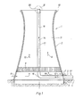
- the cooling tower 1 shown in FIG. 1 has a parabolic cooling tower shell 2 made of concrete. It stands above a water cup, generally designated 3 and embedded in the floor 4, on supports or struts 5, through the gaps of which atmospheric air can flow into the cooling tower in the direction of the arrows 6, 7. In countercurrent to the air, cooling water is rained down via internals 8. Above the internals, the exhaust air flows in the direction of arrows 9, 10 through the chimney 11 of the cooling tower 1 with considerable buoyancy because of the heating by the water to be cooled. This already creates a swath.
- a pipe 11 serves as a feed line for the exhaust gases of a furnace and can be charged with the exhaust gases of a wet separator, which is used for desulfurization of the flue gases, but can also be charged with unpurified exhaust gases via a bypass on the wet separator.
- the exhaust gases flow in the direction of arrows 12, 14 first through a horizontal branch 15 of the feed line, which is radially inserted below the internals 8 in the cooling tower, and from there via a manifold 16 into a vertical pipeline string 17, which is laid in the axis of rotation 18 of the cooling tower paraboloid.
- the cooling tower shell 2 has a crown 19 which is reinforced like a ring in the illustrated embodiment.
- the mouth 20 of the feed line 11 ', i.e. of the vertical pipe string 17 is located somewhat above the crown 19.
- the mouth 20 of the pipe string 17 is concentric with the crown 19.
- a nozzle 23 with an annular flange 24 is on the upper pipe section 21 of the tubular string 17, ie on the ring flange 22 thereof attached.
- the exhaust gas flow is accelerated in front of the mouth 25, so that it emerges at an increased speed.
- the exhaust air flow in the chimney 11, as in all other sections of the cooling tower shell 2 and its elevation 5 with the supply line 15 to 17, is kept separate from the exhaust air flow 9, 10.
- the exhaust gas flow combined in its supply line 11 ′ is closed to the outside until it reaches the mouth 20 or 25. It is released at the mouth and discharged in a concentric direct current with the exhaust air from the cooling tower rising above the chimney and the swaths carried along.
- the exhaust gas flow is accelerated to a multiple of the exit velocity of the exhaust air flow before it is released.
- the supply line 11 During operation of the power plant, the supply line 11 'receives exhaust gases from wet cleaning, which are accelerated at the mouth with the rising exhaust air flow. When the system is started up, uncleaned exhaust gas can can be discharged through the inlet 11 'via the mouth.
Landscapes
- Engineering & Computer Science (AREA)
- Mechanical Engineering (AREA)
- General Engineering & Computer Science (AREA)
- Chemical & Material Sciences (AREA)
- Combustion & Propulsion (AREA)
- Treating Waste Gases (AREA)
Priority Applications (1)
| Application Number | Priority Date | Filing Date | Title |
|---|---|---|---|
| AT84104682T ATE38088T1 (de) | 1984-03-02 | 1984-04-26 | Verfahren und anlage zum abfuehren der abgase von fossilen brennstoffen, vorzugsweise von rauchgasen mit hilfe des abluftstromes einer kuehlanlage, insbesondere nach dem passieren eines nassabscheiders mit einem kuehlturm. |
Applications Claiming Priority (2)
| Application Number | Priority Date | Filing Date | Title |
|---|---|---|---|
| DE3407705 | 1984-03-02 | ||
| DE3407705 | 1984-03-02 |
Publications (3)
| Publication Number | Publication Date |
|---|---|
| EP0155340A2 true EP0155340A2 (fr) | 1985-09-25 |
| EP0155340A3 EP0155340A3 (en) | 1986-02-05 |
| EP0155340B1 EP0155340B1 (fr) | 1988-10-19 |
Family
ID=6229393
Family Applications (1)
| Application Number | Title | Priority Date | Filing Date |
|---|---|---|---|
| EP84104682A Expired EP0155340B1 (fr) | 1984-03-02 | 1984-04-26 | Procédé et installation d'évacuation des gaz perdus des combustibles fossiles, de préférence des fumées, en particulier àprès passage dans un séparateur par voie humide, à l'aide du courant d'air d'échappement d'une installation de refroidissement, en particulier d'une tour de refroidissement |
Country Status (3)
| Country | Link |
|---|---|
| EP (1) | EP0155340B1 (fr) |
| AT (1) | ATE38088T1 (fr) |
| DE (1) | DE3474713D1 (fr) |
Cited By (4)
| Publication number | Priority date | Publication date | Assignee | Title |
|---|---|---|---|---|
| WO1986005577A1 (fr) * | 1985-03-16 | 1986-09-25 | Saarbergwerke Aktiengesellschaft | Rejet de gaz de fumee par une tour de refroidissement |
| WO1995033966A1 (fr) * | 1994-06-07 | 1995-12-14 | Veag Vereinigte Energiewerke Ag | Systeme permettant de relier les conduites de gaz purifie d'une installation de desulfuration des gaz de fumee d'une usine electrique a combustibles fossiles dans une tour de refroidissement a tirage naturel |
| WO2008056836A1 (fr) | 2006-11-07 | 2008-05-15 | Lg Electronics Inc. | Dispositif d'alimentation en eau pour un sèche-linge et procédé de régulation associé |
| CN102401581A (zh) * | 2011-07-27 | 2012-04-04 | 中国电力工程顾问集团西北电力设计院 | 一种混合通风间冷塔系统及其冷却方法 |
Family Cites Families (2)
| Publication number | Priority date | Publication date | Assignee | Title |
|---|---|---|---|---|
| DE1601137A1 (de) * | 1967-10-31 | 1970-05-06 | Maschb Ag | Aus einem selbstventilierenden Kuehlaggregat und einem Schornstein bestehende Baueinheit fuer Industrieanlagen,insbesondere Kraftwerke |
| DE1941193A1 (de) * | 1969-08-13 | 1971-03-11 | Plein Wagner Soehne | Schornsteinkopf mit aufgesetzter Duese |
-
1984
- 1984-04-26 DE DE8484104682T patent/DE3474713D1/de not_active Expired
- 1984-04-26 EP EP84104682A patent/EP0155340B1/fr not_active Expired
- 1984-04-26 AT AT84104682T patent/ATE38088T1/de not_active IP Right Cessation
Cited By (10)
| Publication number | Priority date | Publication date | Assignee | Title |
|---|---|---|---|---|
| WO1986005577A1 (fr) * | 1985-03-16 | 1986-09-25 | Saarbergwerke Aktiengesellschaft | Rejet de gaz de fumee par une tour de refroidissement |
| US4784810A (en) * | 1985-03-16 | 1988-11-15 | Saarbergwerke Aktiengesellschaft | Smoke gas exhaust by way of a cooling tower |
| US4885011A (en) * | 1985-03-16 | 1989-12-05 | Saarbergwerke Aktiengesellschaft | Cooling tower for the cooling water that drains/ from the condensor of a steam generator or the condensors/ of a plurality of steam generators |
| WO1995033966A1 (fr) * | 1994-06-07 | 1995-12-14 | Veag Vereinigte Energiewerke Ag | Systeme permettant de relier les conduites de gaz purifie d'une installation de desulfuration des gaz de fumee d'une usine electrique a combustibles fossiles dans une tour de refroidissement a tirage naturel |
| AU684186B2 (en) * | 1994-06-07 | 1997-12-04 | Balcke-Durr Energietechnik Gmbh | Device for incorporating the purified-gas ducts from a fossil-fuel power station desulphurization plant in natural-convection wet cooling power |
| WO2008056836A1 (fr) | 2006-11-07 | 2008-05-15 | Lg Electronics Inc. | Dispositif d'alimentation en eau pour un sèche-linge et procédé de régulation associé |
| EP2092106A4 (fr) * | 2006-11-07 | 2011-04-06 | Lg Electronics Inc | Dispositif d'alimentation en eau pour un sèche-linge et procédé de régulation associé |
| US8250777B2 (en) | 2006-11-07 | 2012-08-28 | Lg Electronics Inc. | Device of supplying water for laundry dryer and method for controlling the same |
| CN102401581A (zh) * | 2011-07-27 | 2012-04-04 | 中国电力工程顾问集团西北电力设计院 | 一种混合通风间冷塔系统及其冷却方法 |
| CN102401581B (zh) * | 2011-07-27 | 2013-05-08 | 中国电力工程顾问集团西北电力设计院 | 一种混合通风间冷塔系统及其冷却方法 |
Also Published As
| Publication number | Publication date |
|---|---|
| EP0155340B1 (fr) | 1988-10-19 |
| EP0155340A3 (en) | 1986-02-05 |
| DE3474713D1 (en) | 1988-11-24 |
| ATE38088T1 (de) | 1988-11-15 |
Similar Documents
| Publication | Publication Date | Title |
|---|---|---|
| DE60205274T2 (de) | Methode und apparat zur gaswäsche unter verwendung von leitblechen | |
| DE69205161T2 (de) | Pulsierende atmosphärische wirbelschichtverbrennungsanlage und verfahren. | |
| DE69704953T2 (de) | VERFAHREN UND VERBRENNUNGSAPPARAT MIT EINER VORRICHTUNG ZUR EINSPRITZUNG EINES NOx REDUKTIONSMITTELS | |
| EP0215864B1 (fr) | Rejet de gaz de fumee par une tour de refroidissement | |
| DE68907116T2 (de) | Verfahren zur Reduktion des Gehalts an nichtkondensierbaren Elementen, die sich in kondensierbare Elemente enthaltenden Rauchgasen befinden und darin löslich sind. | |
| DE69201587T2 (de) | Wäscher für mehrere Gase. | |
| DE69006017T2 (de) | Vorrichtung und verfahren zur beseitigung der luftverschmutzung. | |
| EP0616022B1 (fr) | Procédé pour la gazéification sous pression de combustibles finement divisés | |
| EP0132584A2 (fr) | Procédé et installation pour diminuer l'émission de la matière nocive dans les gaz d'échappement des installations de combustion | |
| EP0155340B1 (fr) | Procédé et installation d'évacuation des gaz perdus des combustibles fossiles, de préférence des fumées, en particulier àprès passage dans un séparateur par voie humide, à l'aide du courant d'air d'échappement d'une installation de refroidissement, en particulier d'une tour de refroidissement | |
| EP0089036B1 (fr) | Procédé pour l'épuration des gaz d'échappement et pour la récupération de chaleur ainsi qu'un dispositif pour sa mise en oeuvre | |
| DE3604946C2 (de) | Verfahren und Vorrichtung zur Reinigung von Rauchgasen | |
| DE68906228T2 (de) | Verfahren zum erzeugen von waerme mit einer entschwefelung von abgasen durch absorptionsmittelteilchen feiner teilchengroesse in einem wanderbett. | |
| DE69406778T2 (de) | Methode und vorrichtung zur reinigung von heissem gas und gewinnung von energie aus demselben | |
| AT517338B1 (de) | Rauchgaswärmetauscher und Verfahren zum Betrieb eines Rauchgaswärmetauschers | |
| DE29621346U1 (de) | Vorrichtung zum Behandeln von Abgasen | |
| EP0107144B1 (fr) | Procédé pour l'élimination de polluants de gaz d'échappement, particulièrement de fumées, par condensation | |
| DE69100523T2 (de) | Verfahren und Vorrichtung zur Wärmeerzeugung mit Entschwefelung von Abgasen durch Absorptionsmittelteilchen feiner Teilchengrösse in einem Wanderbett. | |
| DE69309636T2 (de) | Vorrichtung und Verfahren für thermische Zerstörung von sauren Substanzen in Rauchgasen | |
| DE2931773A1 (de) | System zum verringern des schwefeldioxidgehalts | |
| DE69931924T2 (de) | Verfahren zur reinigung von abgas | |
| DE3329342C2 (de) | Verfahren zur Behandlung von Rauchgasen aus einer Dampferzeugungsanlage | |
| DE2844274A1 (de) | Verfahren und vorrichtung zur adsorption von verunreinigungen | |
| DD275725A1 (de) | Verfahren und anlage zur rauchgasentschwefelung | |
| DE3040078C2 (de) | Verfahren zur Entschwefelung von Abgasen flüssiger Brennstoffe |
Legal Events
| Date | Code | Title | Description |
|---|---|---|---|
| PUAI | Public reference made under article 153(3) epc to a published international application that has entered the european phase |
Free format text: ORIGINAL CODE: 0009012 |
|
| AK | Designated contracting states |
Designated state(s): AT BE CH DE FR GB IT LI LU NL SE |
|
| PUAL | Search report despatched |
Free format text: ORIGINAL CODE: 0009013 |
|
| AK | Designated contracting states |
Designated state(s): AT BE CH DE FR GB IT LI LU NL SE |
|
| 17P | Request for examination filed |
Effective date: 19860731 |
|
| 17Q | First examination report despatched |
Effective date: 19870324 |
|
| GRAA | (expected) grant |
Free format text: ORIGINAL CODE: 0009210 |
|
| AK | Designated contracting states |
Kind code of ref document: B1 Designated state(s): AT BE CH DE FR GB IT LI LU NL SE |
|
| PG25 | Lapsed in a contracting state [announced via postgrant information from national office to epo] |
Ref country code: SE Effective date: 19881019 Ref country code: IT Free format text: LAPSE BECAUSE OF FAILURE TO SUBMIT A TRANSLATION OF THE DESCRIPTION OR TO PAY THE FEE WITHIN THE PRESCRIBED TIME-LIMIT;WARNING: LAPSES OF ITALIAN PATENTS WITH EFFECTIVE DATE BEFORE 2007 MAY HAVE OCCURRED AT ANY TIME BEFORE 2007. THE CORRECT EFFECTIVE DATE MAY BE DIFFERENT FROM THE ONE RECORDED. Effective date: 19881019 |
|
| REF | Corresponds to: |
Ref document number: 38088 Country of ref document: AT Date of ref document: 19881115 Kind code of ref document: T |
|
| REF | Corresponds to: |
Ref document number: 3474713 Country of ref document: DE Date of ref document: 19881124 |
|
| ET | Fr: translation filed | ||
| GBT | Gb: translation of ep patent filed (gb section 77(6)(a)/1977) | ||
| PG25 | Lapsed in a contracting state [announced via postgrant information from national office to epo] |
Ref country code: AT Effective date: 19890426 |
|
| PG25 | Lapsed in a contracting state [announced via postgrant information from national office to epo] |
Ref country code: LU Free format text: LAPSE BECAUSE OF NON-PAYMENT OF DUE FEES Effective date: 19890430 Ref country code: LI Effective date: 19890430 Ref country code: CH Effective date: 19890430 |
|
| PLBE | No opposition filed within time limit |
Free format text: ORIGINAL CODE: 0009261 |
|
| STAA | Information on the status of an ep patent application or granted ep patent |
Free format text: STATUS: NO OPPOSITION FILED WITHIN TIME LIMIT |
|
| 26N | No opposition filed | ||
| REG | Reference to a national code |
Ref country code: CH Ref legal event code: PL |
|
| PGFP | Annual fee paid to national office [announced via postgrant information from national office to epo] |
Ref country code: NL Payment date: 19910430 Year of fee payment: 8 |
|
| PG25 | Lapsed in a contracting state [announced via postgrant information from national office to epo] |
Ref country code: NL Effective date: 19921101 |
|
| NLV4 | Nl: lapsed or anulled due to non-payment of the annual fee | ||
| PGFP | Annual fee paid to national office [announced via postgrant information from national office to epo] |
Ref country code: GB Payment date: 19930413 Year of fee payment: 10 |
|
| PGFP | Annual fee paid to national office [announced via postgrant information from national office to epo] |
Ref country code: FR Payment date: 19930417 Year of fee payment: 10 |
|
| PG25 | Lapsed in a contracting state [announced via postgrant information from national office to epo] |
Ref country code: GB Effective date: 19940426 |
|
| PGFP | Annual fee paid to national office [announced via postgrant information from national office to epo] |
Ref country code: BE Payment date: 19940506 Year of fee payment: 11 |
|
| GBPC | Gb: european patent ceased through non-payment of renewal fee |
Effective date: 19940426 |
|
| PG25 | Lapsed in a contracting state [announced via postgrant information from national office to epo] |
Ref country code: FR Effective date: 19941229 |
|
| REG | Reference to a national code |
Ref country code: FR Ref legal event code: ST |
|
| PG25 | Lapsed in a contracting state [announced via postgrant information from national office to epo] |
Ref country code: BE Effective date: 19950430 |
|
| BERE | Be: lapsed |
Owner name: S.A. HAMON-SOBELCO Effective date: 19950430 |
|
| PGFP | Annual fee paid to national office [announced via postgrant information from national office to epo] |
Ref country code: DE Payment date: 19970625 Year of fee payment: 14 |
|
| PG25 | Lapsed in a contracting state [announced via postgrant information from national office to epo] |
Ref country code: DE Free format text: LAPSE BECAUSE OF NON-PAYMENT OF DUE FEES Effective date: 19990202 |