EP0155438B1 - Maschine mit Schwingbewegung - Google Patents
Maschine mit Schwingbewegung Download PDFInfo
- Publication number
- EP0155438B1 EP0155438B1 EP84830364A EP84830364A EP0155438B1 EP 0155438 B1 EP0155438 B1 EP 0155438B1 EP 84830364 A EP84830364 A EP 84830364A EP 84830364 A EP84830364 A EP 84830364A EP 0155438 B1 EP0155438 B1 EP 0155438B1
- Authority
- EP
- European Patent Office
- Prior art keywords
- tub
- tumblers
- base
- vibratory
- stations
- Prior art date
- Legal status (The legal status is an assumption and is not a legal conclusion. Google has not performed a legal analysis and makes no representation as to the accuracy of the status listed.)
- Expired - Lifetime
Links
Images


Classifications
-
- B—PERFORMING OPERATIONS; TRANSPORTING
- B24—GRINDING; POLISHING
- B24B—MACHINES, DEVICES, OR PROCESSES FOR GRINDING OR POLISHING; DRESSING OR CONDITIONING OF ABRADING SURFACES; FEEDING OF GRINDING, POLISHING, OR LAPPING AGENTS
- B24B31/00—Machines or devices designed for polishing or abrading surfaces on work by means of tumbling apparatus or other apparatus in which the work and/or the abrasive material is loose; Accessories therefor
- B24B31/06—Machines or devices designed for polishing or abrading surfaces on work by means of tumbling apparatus or other apparatus in which the work and/or the abrasive material is loose; Accessories therefor involving oscillating or vibrating containers
-
- C—CHEMISTRY; METALLURGY
- C23—COATING METALLIC MATERIAL; COATING MATERIAL WITH METALLIC MATERIAL; CHEMICAL SURFACE TREATMENT; DIFFUSION TREATMENT OF METALLIC MATERIAL; COATING BY VACUUM EVAPORATION, BY SPUTTERING, BY ION IMPLANTATION OR BY CHEMICAL VAPOUR DEPOSITION, IN GENERAL; INHIBITING CORROSION OF METALLIC MATERIAL OR INCRUSTATION IN GENERAL
- C23G—CLEANING OR DE-GREASING OF METALLIC MATERIAL BY CHEMICAL METHODS OTHER THAN ELECTROLYSIS
- C23G3/00—Apparatus for cleaning or pickling metallic material
Definitions
- the present invention relates to a tumbling machine and according to the preamble of claim 1.
- a machine is known from US-A-3624970 is particularly suited to carry out a series of finishing operations, such as degreasing, pickling, fettling or dressing-off,smoothing,washing and protection of mechanical components.
- Both the rectilinear machines and the spiral machines have considerable overall size, and in both cases the pieces to be processed remain in the machine for a period of time that is proportional to the length of the machine and to the speed at which the piece advances, being, however, sufficient to carry out a single operation, for example, the dressing-off of the piece.
- the speed of advancement of the piece may not, furthermore, be reduced beyond a reasonable limit, since any excessive slowing down thereof causes it to advance irregularly, and an excessive build-up of the pieces may arise, with the possibility of their damaging each other.
- US-A-3,624,970 discloses a finishing machine comprising a plurality of finishing chambers joined together in the form of closed circle, but the chambers cannot move.
- the object of the present invention is to provide a tumbling machine capable of overcoming the disadvantages referred to above and thus capable of ensuring a processing time for the piece or the pieces that is absolutely constant and widely adjustable with, furthermore, the possibility of carrying out, with almost total automation, a tumbling cycle in which the piece undergoes various treatments.
- Figure 1 is a schematic plan view from above the tumbling machine according to the invention.
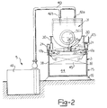
- Figure 2 is a cross-sectional view along the line II-II of Figure 1;
- Figure 4 is a scrap sectional view of a detail of the wear-resistant shell of a vibratory barrel of a tumbling machine according to the invention.
- the machine comprises a plurality of tumblers 2a, b, c, d, e, f and g of the vibratory-tub type, a carousel support structure 3 on each tumbler is mounted, a series of processing stations 4, 5, 6, 7, 8, and 9 facing the carousel structure 3 on the perimeter thereof, and intermittent drive means 10 to advance the plurality of tumblers 2a, b, c, d, e, f and g in relative to the processing stations 4, 5, 6, 7, 8 and 9.
- the carousel support structure 3 includes an annular base 15 supported upon a pedestal 16 and to which is fixed a guide 17 formed by a pair of circular concentric tracks 17a, 17b supported on the lateral walls 18 of the base 15.
- Each tumbler 2a, 2b, 2c, 2d, 2e, 2f, 2g includes a frame 20 movable along the tracks 17a, 17b by means of supporting wheels 21 and guide wheels 22, all of which are freely rotatably mounted on the frame.
- Each of the frames 20 is provided with a pair of buffers 25a, 25b at opposite ends, each provided with a buffer pad 26 and disposed in such a way that corresponding buffer pads of adjacent frames are in contact with each other.
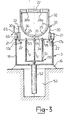
- a vibratory tub 31 is supported by means of springs 30,the details of the tub being more clearly visible in Figure 3; the vibratory tub 31 comprises an outer casing 32 to which the suspension springs 30 are connected by means of brackets 33.
- the tub 31 is closed at the bottom by a curved base 34, in which there is a plurality of holes 35, and has an internal wear-resistant lining 36.
- the mouth of the tub 31 opposite the base 34 is closed by a removable cover 37 made of or coated with sound-absorbent matrial, and in which there are formed slits 38a, 38b for the introduction of processing liquid.
- cover 37 should be supported directly upon the frame 20, for example, by means of studs, not shown.
- the introduction of liquid occurs at one or more of the processing stations 5, 6, 7, 8 and 9, each of which is equipped with a pipe 40 drawing from a reservoir 41 and terminating in a pair of spouts 42a, 42b aligned with the corresponding slits 38a, 38b of the cover 37.
- the spouts 42a, 42b have a longitudinal extension which is smaller in size than the slits, so as not to require a precise positioning of the corresponding tumbler 2 upon the carousel structure 3 for the introduction of liquid into the tub 31.
- the processing liquid introduced through the spouts 42a, 42b immediately flows from the tub 31 through the holes 35, draining into a collecting basin 44, formed in the base 15 of the carousel structure so as to be aligned with each of the processing stations equipped with spouts 42a, 42b.
- the collecting basins 44 preferably have two inclined walls 45 disposed at opposite circumferential ends on the base so as to form a preferential mouth for recovery of the processing liquid, its filtering and possible return to the corresponding reservoir 41.
- the station 4 at which loading and unloading of the piece or pieces to be processed in each tumbler is carried out, is provided with a vertically movable fork element 50 located in the base 15 and formed by a plurality of prongs 51,directed towards the base 34 of the overhead tub 31.
- the fork element 50 is movable by a fluid pressure actuator 52 housed in a sump 53 below the pedestal 16.
- the prongs 51 are thrust through the holes 35 of the base 34 of the tub 31, and are located in these holes with play in such a way as to lift the piece being processed out of the tub.
- Each of the prongs 51 is provided at its upper end with a tip 55 made in a soft material so as to avoid any damage to the piece during lifting of the latter.
- motor vibrators 56a, 56b of standard type, which impart vibratory stresses to granules, not shown, contained n the tub 31.
- the intermittent drive means 10 comprise a thrust cylinder 60, pivotally mounted on the base 15 to which it is connected by means of a lug 61, and a training cylinder 62, also pivotally mounted by means of an eyelet on the base 15 and acting upon the thrust-cylinder 60 to effect training movement thereof.
- the cylinder 60 has a stem 63 provided with a fork 64 which is removably engaged with a stake 65 carried by a striker 66 fixed to the frame 20 of each tumbler.
- the station 4 is further equipped with a movable arm 70 of standard type for loading and unloading the pieces undergoing treatment or for the removal of the cover 27.
- the wear-resistant lining 36 to advantage has a plurality of parallel inwardly projecting ribs 71 which prevent the piece from bearing critically upon the base 34 of the tub 31, thus avoiding any accidental damage 69 the piece.
- the tumbling machine functions as follows: at station 4 the piece is loaded/unloaded into or out of the tubs 31 of the tumbler during its temporary transit beneath this station.
- each of the tubs 31 in addition to the pieces to be processed, there are present granules of a conventional type of the size, conformation and in the quantity desired.
- the prongs 51 of the fork element 50 penetrate the holes 35 of the tubs 31, so lifting the piece or pieces immersed in the granules through the mouth of the tank 31, the cover 37 having been previously removed.
- the prongs 51 serve to free these holes of any granules that may possibly have become stuck therein or from any other possible obstruction.
- the intermittent drive means 10 act upn the tumbler immediately preceding this so as to transfer it into a precise position above the fork element.
- the thrust cylinder 60 retracts its rod 63 and is then trained by the fluid pressure cylinder 62 which carries this, in a retracted state, into a position opposite the striker 66 on the frame 20 of the tumbler 2g.
- the training cylinder 62 is then disposed in a neutral position and follows the displacement caused by the main thrust cylinder 60 in transferring the tumbler 2g from the station 9 to the station 4.
- the motor-vibrators carried on the tub 31 serve in a manner known per se to vibrate it to effect mechanical abrasion of the pieces.
- the liquid introduced is drained through the holes 35, through which any undersized or worn granules, also pass, and is collected in the basin 44 formed in the base at each of the positions 5, 6, 7, 8 and 9.
- the motor-vibrators may be inverted, in particular, if it is necessary to treat pieces with oppositely and threaded blind holes, which process permits all such holes to be freed from dirt, burrs and the like.
- each of the said frames 20 carries two or more barrels up to the point where, for small-capacity tumblers, there is a single frame with a rotatable platform supporting the entire series of vibratory tubs.
Landscapes
- Chemical & Material Sciences (AREA)
- Engineering & Computer Science (AREA)
- Mechanical Engineering (AREA)
- Chemical Kinetics & Catalysis (AREA)
- General Chemical & Material Sciences (AREA)
- Materials Engineering (AREA)
- Metallurgy (AREA)
- Organic Chemistry (AREA)
- Finish Polishing, Edge Sharpening, And Grinding By Specific Grinding Devices (AREA)
- Apparatuses For Bulk Treatment Of Fruits And Vegetables And Apparatuses For Preparing Feeds (AREA)
- General Electrical Machinery Utilizing Piezoelectricity, Electrostriction Or Magnetostriction (AREA)
- Soil Working Implements (AREA)
- Grinding And Polishing Of Tertiary Curved Surfaces And Surfaces With Complex Shapes (AREA)
- Threshing Machine Elements (AREA)
- Transition And Organic Metals Composition Catalysts For Addition Polymerization (AREA)
- Pharmaceuticals Containing Other Organic And Inorganic Compounds (AREA)
Claims (1)
- Eine Maschine (1) mit Schwingbewegung mit Schwingertanken (31) wohin die Teile die berabaiten werden sollen gestellt werden, die eine Mehrheit von Schwingertanken (2), eine ringformige Struktur (3) worauf die genannte Schwingertanken (2) beweglich getragen sind, eine oder mehrere Bearbeitungstelle (4-9) die der obengenannten Struktur (3) gegenüberstehen, aufweist dadurch gekennzeichnet, daß die Maschine (1) intermittierende Führungsmittel (10) zum Fortschritt der Schwingertanken (2) auf die genannte Struktur (3) im Verhältnis zu der genannten Bearbeittungstellen (4-9) aufweist; jeder Schwingertanke (31) eine Basis (34) mit Löchern (35) aufweist; mindestens eine der genannten Bearbeitungsstellen (4-9) eine Ladung/Ausladungstelle (4) für die Teile die bearbeiten werden ist und eine Gabel (50) mit Spitzen (51) nach der Richtung der genannten Basis (34) die durch die gennanten Löchern (35) in den Schwingertank (31) eingeschieben und herausgezogen werden können aufweist.
Priority Applications (1)
| Application Number | Priority Date | Filing Date | Title |
|---|---|---|---|
| AT84830364T ATE62514T1 (de) | 1984-03-20 | 1984-12-31 | Maschine mit schwingbewegung. |
Applications Claiming Priority (2)
| Application Number | Priority Date | Filing Date | Title |
|---|---|---|---|
| IT20143/84A IT1173896B (it) | 1984-03-20 | 1984-03-20 | Macchina burattatrice |
| IT2014384 | 1984-03-20 |
Publications (3)
| Publication Number | Publication Date |
|---|---|
| EP0155438A2 EP0155438A2 (de) | 1985-09-25 |
| EP0155438A3 EP0155438A3 (en) | 1988-05-11 |
| EP0155438B1 true EP0155438B1 (de) | 1991-04-10 |
Family
ID=11164147
Family Applications (1)
| Application Number | Title | Priority Date | Filing Date |
|---|---|---|---|
| EP84830364A Expired - Lifetime EP0155438B1 (de) | 1984-03-20 | 1984-12-31 | Maschine mit Schwingbewegung |
Country Status (4)
| Country | Link |
|---|---|
| EP (1) | EP0155438B1 (de) |
| AT (1) | ATE62514T1 (de) |
| DE (1) | DE3484437D1 (de) |
| IT (1) | IT1173896B (de) |
Families Citing this family (3)
| Publication number | Priority date | Publication date | Assignee | Title |
|---|---|---|---|---|
| IT1190054B (it) * | 1986-02-27 | 1988-02-10 | Reni Cirillo Srl | Macchina per il finissaggio di pezzi metallici |
| EP2789806B1 (de) | 2013-04-10 | 2017-06-14 | Nuovo Pignone S.r.l. | Verfahren und System zur Vorbeugung von Schmierölaustritt in Gasturbinen |
| CN114012593A (zh) * | 2021-11-25 | 2022-02-08 | 中国航发哈尔滨轴承有限公司 | 一种大尺寸铝制保持架光饰装置及其光饰方法 |
Family Cites Families (4)
| Publication number | Priority date | Publication date | Assignee | Title |
|---|---|---|---|---|
| FR1298612A (fr) * | 1960-08-10 | 1962-07-13 | Roto Finish Co | Procédé et appareil de finissage et de polissage |
| US3209497A (en) * | 1962-06-28 | 1965-10-05 | Pangborn Corp | Vibratory finishing |
| US3423884A (en) * | 1966-01-12 | 1969-01-28 | Roto Finish Co | Finishing apparatus having a plurality of compartments |
| US3624970A (en) * | 1968-09-10 | 1971-12-07 | Roto Finish Co | Finishing machine having resiliently segmented finishing chamber |
-
1984
- 1984-03-20 IT IT20143/84A patent/IT1173896B/it active
- 1984-12-31 AT AT84830364T patent/ATE62514T1/de not_active IP Right Cessation
- 1984-12-31 EP EP84830364A patent/EP0155438B1/de not_active Expired - Lifetime
- 1984-12-31 DE DE8484830364T patent/DE3484437D1/de not_active Expired - Lifetime
Also Published As
| Publication number | Publication date |
|---|---|
| IT1173896B (it) | 1987-06-24 |
| EP0155438A3 (en) | 1988-05-11 |
| DE3484437D1 (de) | 1991-05-16 |
| IT8420143A0 (it) | 1984-03-20 |
| EP0155438A2 (de) | 1985-09-25 |
| ATE62514T1 (de) | 1991-04-15 |
| IT8420143A1 (it) | 1985-09-20 |
Similar Documents
| Publication | Publication Date | Title |
|---|---|---|
| US4373296A (en) | Deburring apparatus for workpieces | |
| EP0155438B1 (de) | Maschine mit Schwingbewegung | |
| US4693037A (en) | Multistage finishing device and method | |
| US2461113A (en) | Fluid treatment equipment | |
| US2482269A (en) | Tilting workpiece support, especially for use with processing equipment for containers | |
| CN215659463U (zh) | 可对不同直径的矿山用耐磨球进行固定的耐磨球加工装置 | |
| CN208976379U (zh) | 自动清洗机 | |
| ATE24677T1 (de) | Vorrichtungen zum reinigen/nachbearbeiten von werkstuecken. | |
| CN86106247A (zh) | 复合滚筒抛光加工方法及其装置 | |
| JPS6362599B2 (de) | ||
| JPH0688206B2 (ja) | 全自動ジヤイロ加工機 | |
| US5027558A (en) | Device for treating the surface of an article with solid particles | |
| US4753255A (en) | Closure apparatus for rotating open top container | |
| US2803093A (en) | Horizontal gyrofinishing machine and method | |
| US2921412A (en) | Rotary machine for processing workpieces | |
| JPS6039164A (ja) | 表面処理装置 | |
| CN222289493U (zh) | 一种斜床身机床用接料装置 | |
| JPH0720561B2 (ja) | 遠心分離機及び遠心分離機の固形物回収方法 | |
| JPS6033623B2 (ja) | 自動選別装置付円筒バレル研摩機 | |
| CN112792692A (zh) | 一种抛光精度高的温控型打磨机 | |
| US2700254A (en) | Rotary burnishing machine for formed metal articles | |
| CN112428033A (zh) | 一种自动检测磨砂轮形变程度的轴承磨削机 | |
| JPS61194199A (ja) | 被処理物の取出及びバレルの洗浄装置 | |
| JPS61178169A (ja) | 複合バレル加工法及び装置 | |
| JPS6132998Y2 (de) |
Legal Events
| Date | Code | Title | Description |
|---|---|---|---|
| PUAI | Public reference made under article 153(3) epc to a published international application that has entered the european phase |
Free format text: ORIGINAL CODE: 0009012 |
|
| AK | Designated contracting states |
Designated state(s): AT BE CH DE FR GB LI LU NL SE |
|
| PUAL | Search report despatched |
Free format text: ORIGINAL CODE: 0009013 |
|
| AK | Designated contracting states |
Kind code of ref document: A3 Designated state(s): AT BE CH DE FR GB LI LU NL SE |
|
| 17P | Request for examination filed |
Effective date: 19880803 |
|
| 17Q | First examination report despatched |
Effective date: 19891207 |
|
| GRAA | (expected) grant |
Free format text: ORIGINAL CODE: 0009210 |
|
| AK | Designated contracting states |
Kind code of ref document: B1 Designated state(s): AT BE CH DE FR GB LI LU NL SE |
|
| REF | Corresponds to: |
Ref document number: 62514 Country of ref document: AT Date of ref document: 19910415 Kind code of ref document: T |
|
| ET | Fr: translation filed | ||
| REF | Corresponds to: |
Ref document number: 3484437 Country of ref document: DE Date of ref document: 19910516 |
|
| PLBE | No opposition filed within time limit |
Free format text: ORIGINAL CODE: 0009261 |
|
| STAA | Information on the status of an ep patent application or granted ep patent |
Free format text: STATUS: NO OPPOSITION FILED WITHIN TIME LIMIT |
|
| 26N | No opposition filed | ||
| PGFP | Annual fee paid to national office [announced via postgrant information from national office to epo] |
Ref country code: AT Payment date: 19921029 Year of fee payment: 9 |
|
| PGFP | Annual fee paid to national office [announced via postgrant information from national office to epo] |
Ref country code: LU Payment date: 19921202 Year of fee payment: 9 |
|
| PGFP | Annual fee paid to national office [announced via postgrant information from national office to epo] |
Ref country code: SE Payment date: 19921217 Year of fee payment: 9 |
|
| PGFP | Annual fee paid to national office [announced via postgrant information from national office to epo] |
Ref country code: CH Payment date: 19921221 Year of fee payment: 9 |
|
| PGFP | Annual fee paid to national office [announced via postgrant information from national office to epo] |
Ref country code: NL Payment date: 19921231 Year of fee payment: 9 |
|
| EPTA | Lu: last paid annual fee | ||
| PG25 | Lapsed in a contracting state [announced via postgrant information from national office to epo] |
Ref country code: LU Free format text: LAPSE BECAUSE OF NON-PAYMENT OF DUE FEES Effective date: 19931231 Ref country code: LI Effective date: 19931231 Ref country code: CH Effective date: 19931231 Ref country code: AT Effective date: 19931231 |
|
| PG25 | Lapsed in a contracting state [announced via postgrant information from national office to epo] |
Ref country code: SE Effective date: 19940101 |
|
| PG25 | Lapsed in a contracting state [announced via postgrant information from national office to epo] |
Ref country code: NL Effective date: 19940701 |
|
| NLV4 | Nl: lapsed or anulled due to non-payment of the annual fee | ||
| REG | Reference to a national code |
Ref country code: CH Ref legal event code: PL |
|
| EUG | Se: european patent has lapsed |
Ref document number: 84830364.0 Effective date: 19940810 |
|
| PGFP | Annual fee paid to national office [announced via postgrant information from national office to epo] |
Ref country code: BE Payment date: 19971203 Year of fee payment: 14 |
|
| PG25 | Lapsed in a contracting state [announced via postgrant information from national office to epo] |
Ref country code: BE Free format text: LAPSE BECAUSE OF NON-PAYMENT OF DUE FEES Effective date: 19981231 |
|
| BERE | Be: lapsed |
Owner name: RENI CIRILLO S.R.L. Effective date: 19981231 |
|
| PGFP | Annual fee paid to national office [announced via postgrant information from national office to epo] |
Ref country code: FR Payment date: 19991228 Year of fee payment: 16 |
|
| PGFP | Annual fee paid to national office [announced via postgrant information from national office to epo] |
Ref country code: GB Payment date: 19991229 Year of fee payment: 16 |
|
| PG25 | Lapsed in a contracting state [announced via postgrant information from national office to epo] |
Ref country code: GB Free format text: LAPSE BECAUSE OF NON-PAYMENT OF DUE FEES Effective date: 20001231 |
|
| PGFP | Annual fee paid to national office [announced via postgrant information from national office to epo] |
Ref country code: DE Payment date: 20010222 Year of fee payment: 17 |
|
| GBPC | Gb: european patent ceased through non-payment of renewal fee |
Effective date: 20001231 |
|
| PG25 | Lapsed in a contracting state [announced via postgrant information from national office to epo] |
Ref country code: FR Free format text: LAPSE BECAUSE OF NON-PAYMENT OF DUE FEES Effective date: 20010831 |
|
| REG | Reference to a national code |
Ref country code: FR Ref legal event code: ST |
|
| PG25 | Lapsed in a contracting state [announced via postgrant information from national office to epo] |
Ref country code: DE Free format text: LAPSE BECAUSE OF NON-PAYMENT OF DUE FEES Effective date: 20020702 |