EP0155448A2 - Circuit pour instrument de musique électronique - Google Patents
Circuit pour instrument de musique électronique Download PDFInfo
- Publication number
- EP0155448A2 EP0155448A2 EP85100399A EP85100399A EP0155448A2 EP 0155448 A2 EP0155448 A2 EP 0155448A2 EP 85100399 A EP85100399 A EP 85100399A EP 85100399 A EP85100399 A EP 85100399A EP 0155448 A2 EP0155448 A2 EP 0155448A2
- Authority
- EP
- European Patent Office
- Prior art keywords
- memory
- circuit arrangement
- arrangement according
- circuit
- short
- Prior art date
- Legal status (The legal status is an assumption and is not a legal conclusion. Google has not performed a legal analysis and makes no representation as to the accuracy of the status listed.)
- Withdrawn
Links
Images


Classifications
-
- G—PHYSICS
- G10—MUSICAL INSTRUMENTS; ACOUSTICS
- G10H—ELECTROPHONIC MUSICAL INSTRUMENTS; INSTRUMENTS IN WHICH THE TONES ARE GENERATED BY ELECTROMECHANICAL MEANS OR ELECTRONIC GENERATORS, OR IN WHICH THE TONES ARE SYNTHESISED FROM A DATA STORE
- G10H1/00—Details of electrophonic musical instruments
- G10H1/36—Accompaniment arrangements
Definitions
- the invention relates to an electronic musical instrument, in particular a keyboard instrument.
- Such instruments are commercially available in a wide variety of designs.
- the sound mixture to be reproduced is digitally synthesized, and circuit arrangements are also known in which a chord recognition circuit recognizes a key that is being played and generates corresponding filler tones as accompaniment, such instruments also having input options for selected basic rhythms, cf. DE-PS 3 023 578.
- the object of the present invention is to provide a circuit arrangement for an electronic musical instrument which enables automatic improvisation.
- Pitch data is read from addresses that are generated by a random number generator in a memory that contains data representing the best sound frequencies.
- the decision circuit is used to compare the data of a pitch with that of the one previously read out and to determine whether certain selection criteria are met; these selection criteria are selected manually according to the level of difficulty of the teaching material.
- a certain tone duration is then assigned to a pitch found to be useful and stored in a buffer. For this purpose, data that are representative of such tone durations are stored in a further memory and are also read out with addressing by a random generator.
- Such an organ has switches as input organs for basic rhythms, which are assigned, for example, to certain dance rhythms ("Viennese Waltz”, “Tango”, “Rock 'n Roll” etc.).
- the rhythms are heard in the form of sequential patterns of percussion tones via the organ's playback arrangement.
- the circuit arrangement according to the invention is now influenced by the activation of any such basic rhythm in two ways: on the one hand, certain tone duration data can be blocked (for example triplets in the case of "roll 'n roll”), on the other hand the likelihood that certain tone duration data will be addressed is changed.
- the improviser arrangement initially interprets the input of at least one root note to mean that it is a major key with the entered root note - which is struck, for example, in the lower manual - and the total number of available pitch data is only used for improvisation, which result in "defined" chords based on a standard harmony or that match this key with any chosen basic rhythm. - If several keys of the lower manual are struck at the same time, the corresponding chord for improvisation is determined from them.
- a selection logic is assigned to the pitch data memory in such a way that this data is not read out one after the other completely randomly, but rather that any sequence of tones selected by the random generator, e.g. a sequence increasing in frequency, in the subsequent periods or (partial) bars according to the usual rules of composition theory is modified by retrograding, inverting, etc., in much the same way that an experienced improviser would handle.
- the selection logic accordingly specifies tone sequence patterns to which certain probabilities are still assigned, and these probabilities can in turn be changed in accordance with the selected basic rhythm.
- the improviser arrangement according to the invention provides a catalog of musical form elements (rhythm patterns and tone sequence patterns) and a catalog of linking rules for them, while the selection from them, on the one hand, is random, with the aim of great musical variation, and, on the other hand, is bound by the data entered by the player is made.
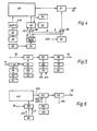
- Fig. 1 denotes a block "organ circuit".
- This block comprises all the usual sound generation and reproduction devices of any known, for example digitally working, instrument which generates tones in accordance with struck keys, the timbre of which can be selected by the player through fixed and setting registers.
- the improviser arrangement 14 is influenced by one of the manuals, for example the lower manual 12 of a two-manual instrument flows. It is also influenced by a basic rhythm generator 16, by means of which the player adjusts the rhythm automatic which is usually present in the organ circuit.
- Manual 12 provides on-off commands to the tone generating devices contained in the organ circuit, and the improviser arrangement also delivers such on-off commands.
- the improviser arrangement comprises a tone duration data memory 18 with an associated selection logic circuit 20 and a random generator 22 associated therewith, a pitch data memory 24 with an associated selection logic circuit 26 and an associated random generator 28, as well as a combination circuit 30 in which the read-out data is combined to the mentioned on-off commands will.
- the tone duration data memory is influenced by the set basic rhythm
- the pitch data memory is influenced by the key (s) struck on the manual 12 in each case.
- the module shown in Fig. 3 generates the signals "sound on” (corresponding to "key pressed”) and “sound off” (corresponding to "key released”), while no decision has yet been made in this module about the respective level of the sounds to be reproduced .
- TSRO, TSR1, TSR2 and TSR3 are provided, in which the - relative - on-off times for one half cycle of two successive cycles in the form of digi taler data are stored.
- the shortest unit of time represented by a bit corresponds to one forty-eighth of a measure or whole note.
- the memories TSRO, TSR1, TSR2 and TSR3 are controlled from an address register SRA, but only two of these addresses are determined by the output signal of the random number generator 22, namely the addresses ASRO and ASR1. Short rhythms are not stored arbitrarily in the memories TSRO, TSR1, TSR2 and TSR3, but "short response rhythms" are stored in the memories TSR3 and TSR2, respectively, which correspond to the "short question rhythms" (musical; "fit” under homologous addresses of the memories TSRO or TSR 1. This link is also arbitrary.
- Fig. 2 shows the sequence of addressing in the diagram.
- a plurality of basic rhythms can have the same measure, for example four-quarter measure, in common, and accordingly several short rhythms - provided the same measure - can be used in several basic rhythms; however, this is not mandatory.
- a weighting circuit 34 is also assigned to the generator 22 in which the probabilities for the random selection of the addresses AS are tabulated. (The same result would be obtained if the individual short rhythms were stored in the memories TSRO, TSR1, TSR2 and TSR3 only once, or two, three times, etc., according to their desired frequency).
- the absolute duration of the on-off times is determined by the duration of a single cycle, which is generally infinitely variable by the player and which is supplied to a control logic 36 as a "metronome cycle".
- the function of the counter 38 connected to it (clock counter, that counts from zero to seven), 40 (half-cycle counter that counts from zero to three) and 42 (time interval counter that pays from zero to 47) are readily apparent from the above explanations.
- Fig. 3 contains the building blocks for a single basic rhythm. If a different basic rhythm is selected, other memories TSR and other probability or weighting circuits are activated. while the remaining components are assigned to all basic rhythms together.
- the finally read out on-off signals are on the output line 44.
- the level of tones to be played during the "on" signals on line 44 is determined in the manner described below.
- the memory indicates which notes may be used in improvisation by striking chords in the lower manual. If he strikes only one key, this is interpreted as a major chord with the struck note as the fundamental; if he does not hit a key at all, the improviser arrangement remains with the last chord played; If the improviser arrangement is switched on after the instrument has been put into operation without the bottom manual even striking, the arrangement improvises in C major.
- FIG. 4 shows a memory SP in which "short melodies" are stored in the form of sequences of addresses for the pitch memory mentioned.
- a random number generator 46 with an associated one Weighting circuit 48 provides any address with which a "short melody” is read out of memory SP, for which purpose control logic circuit 48 is unlocked by a "tone on” signal on line 44.
- a short melody chosen at random is to fill out two bars (the zeroth and the first) as a "question short melody"; in the next two bars (second and third) the short melody is modified in a manner that is yet to be explained. If the short rhythm on line 44 comprises more tones than the selected short melody contains, the corresponding memory location of the SP memory is read out again cyclically. For example, if the short melody is 2-3-3 - 4 and six tones are required in two measures, 2-3-3-4-2-3 is played. Short melodies read out during the first and second clocks are stored with regard to their end address in a buffer memory 50 in order to be processed into "response short melodies" during the second and third clocks. A flip-flop 52 switches between question and answer clocks.
- Fig. 4 two types of response are provided, namely “mirroring” (R) and “Inversion” (I), which can also be combined with one another (type IR).
- R mirroring
- I Inversion
- the short melody held in the buffer memory 50 is read out backwards during bars two and three, that is to say in the above example the reproduction of the sequence 3-2-4-3-3-2.
- the second type of response, "inversion” means that each individual number of the short melody is subtracted from a given constant and the sequence of numbers thus formed defines the short response melody. Examples:
- the random number generator 54 with associated weighting circuit 56 is used to select the response type.
- the link to the output of the flip-flop 52 is established via gates 58, 60.
- FIG. 4 shows an address counter 62 for the addresses of the memory SP. This is reset to zero after the end of the second cycle or, in the case of mirroring, is loaded from the buffer memory 50 and the "tone on" signals are decremented in time.
- the short melody of bar one can be the same as that of bar zero, and accordingly one can for Proceeding responses; the counter 62 is then already set to zero or the last value held in the buffer 50 with each new clock cycle.
- the signals on line 64 in FIG. 4 go to an adding circuit 66 (FIG. 5), where a "displacement" (absolute pitch shift) and / or a relative displacement - again in accordance with two assigned random number generators 68, 70 with weighting or Probability circuits 72 and 74 can be introduced.
- a "displacement" absolute pitch shift
- / or a relative displacement - again in accordance with two assigned random number generators 68, 70 with weighting or Probability circuits 72 and 74 can be introduced.
- the size of the absolute offset is determined by means of a random number and written into the offset register 76.
- a further random number is written into a relative offset register 78.
- this number is added to that in register 76, and subtracted for answer short melodies (or vice versa).
- the add / subtract circuit 80 is used for this.
- the adder circuit 66 is followed by another adder circuit 82; it is used for transposing. If the player strikes a different key (a key or chord) on the lower manual, the improviser arrangement should adapt. Extreme musical jumps should be avoided for musical reasons.
- This adder circuit 66 is followed by a suppression circuit 88, with the aid of which individual tones can be replaced by pauses in accordance with the numbers generated by a further random number generator 90 with weighting circuit 92.
- the data read from the memory AN arrive at a suggestion circuit 102.
- the pitch is briefly lowered by half a tone.
- the circuit 102 must therefore be supplied with an unlock signal on line 108, which can be derived from the data held in the SR memory and read out under the control of the metronome clock.
- the transpose circuit 110 follows, which carries out the conversion in accordance with the respectively valid basic tone RN.
- the output line 112 then contains signals which correspond exactly in their form to those which are generated by hitting any key, so that they can be fed to the decoding circuits of the actual tone generation circuits.
- Fig. 7 shows schematically some bars of an improvised melody according to the invention in notation with the corresponding processes of signal processing.
- Line (a) shows the time scale, which is reproduced in bars of the melody. A total of eight bars with the names bar 0 to bar 7 are shown.
- Lines (b), (c) and (d) relate to the definition of the rhythm, which is carried out by selecting short rhythm addresses ASRO, ASR1, ASR2, ASR3. Each short rhythm is defined by ASR and a selected short rhythm memory 1SR.
- line (b) shows the selected ASR addresses
- line (c) the selected memory table TSR
- line (d) an example of rock music rhythm.
- Lines (e), (f), (g), (h), (i) refer to the definition of the respective pitch.
- SP short melody pattern
- the respective admitted grades are stored in the AN memory; they depend on the key played. For example, in C major, the tones C, E, G, A are permitted, whereby the numbers 5 to 80 refer to the same notes in the next higher octave.
- each stroke marks a note to be played back according to the rhythm shown in line (c).
- Line (h) indicates the dislocations that are also used.
- the corresponding values are 0 for the absolute offset and 1 for the relative offset. It should be noted that for clocks 0, 3, 4 and 7 only the absolute offset is effective, while for the remaining clocks the absolute and the relative offset are effective are.
- Line (i) 7 includes the resulting addresses for the AN memory, which holds the approved notes.
- Line (k) which is reproduced in conventional notation, shows the resulting "improvised” accompanying melodies.
Landscapes
- Physics & Mathematics (AREA)
- Engineering & Computer Science (AREA)
- Acoustics & Sound (AREA)
- Multimedia (AREA)
- Electrophonic Musical Instruments (AREA)
- Auxiliary Devices For Music (AREA)
Applications Claiming Priority (2)
| Application Number | Priority Date | Filing Date | Title |
|---|---|---|---|
| DE19843403555 DE3403555A1 (de) | 1984-02-02 | 1984-02-02 | Schaltungsanordnung fuer ein elektronisches musikinstrument |
| DE3403555 | 1984-02-02 |
Publications (2)
| Publication Number | Publication Date |
|---|---|
| EP0155448A2 true EP0155448A2 (fr) | 1985-09-25 |
| EP0155448A3 EP0155448A3 (fr) | 1987-09-23 |
Family
ID=6226531
Family Applications (1)
| Application Number | Title | Priority Date | Filing Date |
|---|---|---|---|
| EP85100399A Withdrawn EP0155448A3 (fr) | 1984-02-02 | 1985-01-16 | Circuit pour instrument de musique électronique |
Country Status (3)
| Country | Link |
|---|---|
| EP (1) | EP0155448A3 (fr) |
| JP (1) | JPS60181794A (fr) |
| DE (1) | DE3403555A1 (fr) |
Families Citing this family (1)
| Publication number | Priority date | Publication date | Assignee | Title |
|---|---|---|---|---|
| JPH07113828B2 (ja) * | 1987-05-20 | 1995-12-06 | カシオ計算機株式会社 | 自動作曲機 |
Family Cites Families (3)
| Publication number | Priority date | Publication date | Assignee | Title |
|---|---|---|---|---|
| JPS564192A (en) * | 1979-06-25 | 1981-01-17 | Nippon Musical Instruments Mfg | Automatic player |
| US4375177A (en) * | 1981-04-13 | 1983-03-01 | John Larson | Automatic electronic musical instrument |
| US4399731A (en) * | 1981-08-11 | 1983-08-23 | Nippon Gakki Seizo Kabushiki Kaisha | Apparatus for automatically composing music piece |
-
1984
- 1984-02-02 DE DE19843403555 patent/DE3403555A1/de not_active Withdrawn
-
1985
- 1985-01-16 EP EP85100399A patent/EP0155448A3/fr not_active Withdrawn
- 1985-02-02 JP JP60019159A patent/JPS60181794A/ja active Pending
Also Published As
| Publication number | Publication date |
|---|---|
| DE3403555A1 (de) | 1985-08-08 |
| EP0155448A3 (fr) | 1987-09-23 |
| JPS60181794A (ja) | 1985-09-17 |
Similar Documents
| Publication | Publication Date | Title |
|---|---|---|
| DE3049294C2 (de) | Automatisches Rhythmusbegleitsystem | |
| DE3221447C2 (fr) | ||
| DE69816225T2 (de) | Vorrichtung und Verfahren zur Erzeugung von Arpeggiotönen | |
| DE2107409C3 (de) | Elektronisches Musikinstrument | |
| DE3248144C2 (de) | Vorrichtung für das automatische Erzeugen von Begleitung in einem elektronischen Musikinstrument | |
| DE2056509A1 (de) | Elektrisches Tastenmusikinstrument | |
| DE3103801C2 (de) | Elektronisches Musikinstrument mit Tastenfeld | |
| DE3033534A1 (de) | Elektronisches musikinstrument mit uebungseigenschaften | |
| DE60215750T2 (de) | Vorrichtung und Verfahren zum Anzeigen von Akkorden | |
| DE2053245B2 (de) | Elektronisches musikinstrument | |
| DE3237403C2 (fr) | ||
| DE68907648T2 (de) | Elektronisches musikinstrument. | |
| DE2539950C3 (de) | Bassakkordautomatik | |
| DE3023559C2 (de) | Elektronisches Musikinstrument | |
| DE2111505A1 (de) | Vorrichtung zur automatischen Rhythmusklangerzeugung | |
| DE3135155A1 (de) | Elektronischer apparat mit einem mehrere tasten aufweisendem keyboard | |
| DE3334148A1 (de) | Elektronisches musikinstrument mit automatischer begleitung | |
| DE3605122C2 (fr) | ||
| DE2937256A1 (de) | Digitales elektronisches musikinstrument | |
| DE3023478A1 (de) | Elektronisches musikinstrument | |
| DE2915678C2 (de) | Elektronisches Musikinstrument | |
| DE3047801C2 (de) | Elektronisches Musikinstrument mit Tastenfeld | |
| DE3883631T2 (de) | Für automatische Begleitung geeignetes elektronisches Musikinstrument. | |
| DE1949313B2 (de) | Elektronische orgel | |
| DE3940078C2 (de) | Elektronisches Musikinstrument |
Legal Events
| Date | Code | Title | Description |
|---|---|---|---|
| PUAI | Public reference made under article 153(3) epc to a published international application that has entered the european phase |
Free format text: ORIGINAL CODE: 0009012 |
|
| AK | Designated contracting states |
Designated state(s): DE FR GB IT NL |
|
| PUAL | Search report despatched |
Free format text: ORIGINAL CODE: 0009013 |
|
| AK | Designated contracting states |
Kind code of ref document: A3 Designated state(s): DE FR GB IT NL |
|
| STAA | Information on the status of an ep patent application or granted ep patent |
Free format text: STATUS: THE APPLICATION IS DEEMED TO BE WITHDRAWN |
|
| 18D | Application deemed to be withdrawn |
Effective date: 19880324 |
|
| RIN1 | Information on inventor provided before grant (corrected) |
Inventor name: MANCINI, GEORGE M. Inventor name: HUBER, RUDOLF A., DR. |