EP0155498A2 - Procédé de fabrication d'un échangeur de chaleur et échangeur de chaleur produit comme tel - Google Patents
Procédé de fabrication d'un échangeur de chaleur et échangeur de chaleur produit comme tel Download PDFInfo
- Publication number
- EP0155498A2 EP0155498A2 EP85101559A EP85101559A EP0155498A2 EP 0155498 A2 EP0155498 A2 EP 0155498A2 EP 85101559 A EP85101559 A EP 85101559A EP 85101559 A EP85101559 A EP 85101559A EP 0155498 A2 EP0155498 A2 EP 0155498A2
- Authority
- EP
- European Patent Office
- Prior art keywords
- plastic
- holes
- heat exchanger
- tube
- lined
- Prior art date
- Legal status (The legal status is an assumption and is not a legal conclusion. Google has not performed a legal analysis and makes no representation as to the accuracy of the status listed.)
- Granted
Links
- 238000004519 manufacturing process Methods 0.000 title claims abstract description 12
- 229910052751 metal Inorganic materials 0.000 claims abstract description 40
- 239000002184 metal Substances 0.000 claims abstract description 40
- 239000000463 material Substances 0.000 claims abstract description 26
- 239000002985 plastic film Substances 0.000 claims abstract description 20
- 239000004033 plastic Substances 0.000 claims abstract description 19
- 229920003023 plastic Polymers 0.000 claims abstract description 19
- 230000009467 reduction Effects 0.000 claims abstract description 12
- 230000000750 progressive effect Effects 0.000 claims abstract description 4
- 230000000712 assembly Effects 0.000 claims abstract 4
- 238000000429 assembly Methods 0.000 claims abstract 4
- XLYOFNOQVPJJNP-UHFFFAOYSA-N water Chemical compound O XLYOFNOQVPJJNP-UHFFFAOYSA-N 0.000 claims description 130
- 238000009833 condensation Methods 0.000 claims description 48
- 230000005494 condensation Effects 0.000 claims description 48
- 238000000034 method Methods 0.000 claims description 24
- 238000010438 heat treatment Methods 0.000 claims description 20
- 239000012530 fluid Substances 0.000 claims description 17
- 239000000470 constituent Substances 0.000 claims description 10
- 238000002485 combustion reaction Methods 0.000 claims description 9
- 229920002313 fluoropolymer Polymers 0.000 claims description 4
- 230000008878 coupling Effects 0.000 claims 1
- 238000010168 coupling process Methods 0.000 claims 1
- 238000005859 coupling reaction Methods 0.000 claims 1
- 230000001681 protective effect Effects 0.000 abstract description 2
- 239000003546 flue gas Substances 0.000 description 106
- UGFAIRIUMAVXCW-UHFFFAOYSA-N Carbon monoxide Chemical compound [O+]#[C-] UGFAIRIUMAVXCW-UHFFFAOYSA-N 0.000 description 103
- 239000007789 gas Substances 0.000 description 65
- 239000003570 air Substances 0.000 description 60
- QAOWNCQODCNURD-UHFFFAOYSA-N Sulfuric acid Chemical compound OS(O)(=O)=O QAOWNCQODCNURD-UHFFFAOYSA-N 0.000 description 55
- 229920006362 Teflon® Polymers 0.000 description 52
- 239000004809 Teflon Substances 0.000 description 51
- AKEJUJNQAAGONA-UHFFFAOYSA-N sulfur trioxide Chemical compound O=S(=O)=O AKEJUJNQAAGONA-UHFFFAOYSA-N 0.000 description 28
- 239000013618 particulate matter Substances 0.000 description 24
- 238000005260 corrosion Methods 0.000 description 17
- 230000007797 corrosion Effects 0.000 description 17
- DNIAPMSPPWPWGF-UHFFFAOYSA-N Propylene glycol Chemical compound CC(O)CO DNIAPMSPPWPWGF-UHFFFAOYSA-N 0.000 description 12
- 238000011084 recovery Methods 0.000 description 12
- 239000012080 ambient air Substances 0.000 description 11
- VNWKTOKETHGBQD-UHFFFAOYSA-N methane Chemical compound C VNWKTOKETHGBQD-UHFFFAOYSA-N 0.000 description 10
- BFKJFAAPBSQJPD-UHFFFAOYSA-N tetrafluoroethene Chemical group FC(F)=C(F)F BFKJFAAPBSQJPD-UHFFFAOYSA-N 0.000 description 9
- 239000000446 fuel Substances 0.000 description 8
- 239000011152 fibreglass Substances 0.000 description 7
- 239000007921 spray Substances 0.000 description 6
- 238000000576 coating method Methods 0.000 description 5
- 230000006378 damage Effects 0.000 description 5
- 238000010586 diagram Methods 0.000 description 5
- 239000003345 natural gas Substances 0.000 description 5
- 239000002245 particle Substances 0.000 description 5
- 239000011253 protective coating Substances 0.000 description 5
- XWJRCNQFQUBEAV-NSCUHMNNSA-N (e)-5-fluoropent-2-ene Chemical group C\C=C\CCF XWJRCNQFQUBEAV-NSCUHMNNSA-N 0.000 description 4
- RYGMFSIKBFXOCR-UHFFFAOYSA-N Copper Chemical compound [Cu] RYGMFSIKBFXOCR-UHFFFAOYSA-N 0.000 description 4
- 229910000831 Steel Inorganic materials 0.000 description 4
- 229910052782 aluminium Inorganic materials 0.000 description 4
- XAGFODPZIPBFFR-UHFFFAOYSA-N aluminium Chemical compound [Al] XAGFODPZIPBFFR-UHFFFAOYSA-N 0.000 description 4
- 230000008901 benefit Effects 0.000 description 4
- 238000001816 cooling Methods 0.000 description 4
- 229910052802 copper Inorganic materials 0.000 description 4
- 239000010949 copper Substances 0.000 description 4
- 230000000694 effects Effects 0.000 description 4
- 239000000203 mixture Substances 0.000 description 4
- 239000003921 oil Substances 0.000 description 4
- 239000010959 steel Substances 0.000 description 4
- 238000003860 storage Methods 0.000 description 4
- 238000004140 cleaning Methods 0.000 description 3
- 230000003247 decreasing effect Effects 0.000 description 3
- 238000001035 drying Methods 0.000 description 3
- 238000003780 insertion Methods 0.000 description 3
- 230000037431 insertion Effects 0.000 description 3
- 239000010747 number 6 fuel oil Substances 0.000 description 3
- 230000036961 partial effect Effects 0.000 description 3
- 238000005406 washing Methods 0.000 description 3
- 239000002918 waste heat Substances 0.000 description 3
- NINIDFKCEFEMDL-UHFFFAOYSA-N Sulfur Chemical compound [S] NINIDFKCEFEMDL-UHFFFAOYSA-N 0.000 description 2
- RAHZWNYVWXNFOC-UHFFFAOYSA-N Sulphur dioxide Chemical compound O=S=O RAHZWNYVWXNFOC-UHFFFAOYSA-N 0.000 description 2
- 239000011324 bead Substances 0.000 description 2
- 239000011248 coating agent Substances 0.000 description 2
- 238000010276 construction Methods 0.000 description 2
- 238000005536 corrosion prevention Methods 0.000 description 2
- 230000003628 erosive effect Effects 0.000 description 2
- 230000002209 hydrophobic effect Effects 0.000 description 2
- 239000010743 number 2 fuel oil Substances 0.000 description 2
- 238000005201 scrubbing Methods 0.000 description 2
- 229910052717 sulfur Inorganic materials 0.000 description 2
- 239000011593 sulfur Substances 0.000 description 2
- UFHFLCQGNIYNRP-UHFFFAOYSA-N Hydrogen Chemical compound [H][H] UFHFLCQGNIYNRP-UHFFFAOYSA-N 0.000 description 1
- 229920006356 Teflon™ FEP Polymers 0.000 description 1
- 238000005299 abrasion Methods 0.000 description 1
- 239000002253 acid Substances 0.000 description 1
- 238000003915 air pollution Methods 0.000 description 1
- 239000003245 coal Substances 0.000 description 1
- 239000003034 coal gas Substances 0.000 description 1
- 230000008602 contraction Effects 0.000 description 1
- 239000013256 coordination polymer Substances 0.000 description 1
- PTVDYARBVCBHSL-UHFFFAOYSA-N copper;hydrate Chemical compound O.[Cu] PTVDYARBVCBHSL-UHFFFAOYSA-N 0.000 description 1
- 238000005336 cracking Methods 0.000 description 1
- 238000005520 cutting process Methods 0.000 description 1
- 238000007865 diluting Methods 0.000 description 1
- 238000010790 dilution Methods 0.000 description 1
- 239000012895 dilution Substances 0.000 description 1
- 238000010304 firing Methods 0.000 description 1
- 239000000295 fuel oil Substances 0.000 description 1
- 229910052739 hydrogen Inorganic materials 0.000 description 1
- 239000001257 hydrogen Substances 0.000 description 1
- 230000000670 limiting effect Effects 0.000 description 1
- 230000013011 mating Effects 0.000 description 1
- 239000011159 matrix material Substances 0.000 description 1
- 230000007246 mechanism Effects 0.000 description 1
- 230000008018 melting Effects 0.000 description 1
- 238000002844 melting Methods 0.000 description 1
- 229920001343 polytetrafluoroethylene Polymers 0.000 description 1
- 230000008569 process Effects 0.000 description 1
- 230000001737 promoting effect Effects 0.000 description 1
- 230000002829 reductive effect Effects 0.000 description 1
- 230000008439 repair process Effects 0.000 description 1
- 230000002441 reversible effect Effects 0.000 description 1
- XTQHKBHJIVJGKJ-UHFFFAOYSA-N sulfur monoxide Chemical class S=O XTQHKBHJIVJGKJ-UHFFFAOYSA-N 0.000 description 1
- 229910052815 sulfur oxide Inorganic materials 0.000 description 1
- 230000001052 transient effect Effects 0.000 description 1
Images


Classifications
-
- B—PERFORMING OPERATIONS; TRANSPORTING
- B01—PHYSICAL OR CHEMICAL PROCESSES OR APPARATUS IN GENERAL
- B01D—SEPARATION
- B01D53/00—Separation of gases or vapours; Recovering vapours of volatile solvents from gases; Chemical or biological purification of waste gases, e.g. engine exhaust gases, smoke, fumes, flue gases, aerosols
- B01D53/34—Chemical or biological purification of waste gases
- B01D53/46—Removing components of defined structure
- B01D53/48—Sulfur compounds
- B01D53/50—Sulfur oxides
- B01D53/507—Sulfur oxides by treating the gases with other liquids
-
- B—PERFORMING OPERATIONS; TRANSPORTING
- B01—PHYSICAL OR CHEMICAL PROCESSES OR APPARATUS IN GENERAL
- B01D—SEPARATION
- B01D53/00—Separation of gases or vapours; Recovering vapours of volatile solvents from gases; Chemical or biological purification of waste gases, e.g. engine exhaust gases, smoke, fumes, flue gases, aerosols
- B01D53/002—Separation of gases or vapours; Recovering vapours of volatile solvents from gases; Chemical or biological purification of waste gases, e.g. engine exhaust gases, smoke, fumes, flue gases, aerosols by condensation
-
- B—PERFORMING OPERATIONS; TRANSPORTING
- B01—PHYSICAL OR CHEMICAL PROCESSES OR APPARATUS IN GENERAL
- B01D—SEPARATION
- B01D53/00—Separation of gases or vapours; Recovering vapours of volatile solvents from gases; Chemical or biological purification of waste gases, e.g. engine exhaust gases, smoke, fumes, flue gases, aerosols
- B01D53/005—Separation of gases or vapours; Recovering vapours of volatile solvents from gases; Chemical or biological purification of waste gases, e.g. engine exhaust gases, smoke, fumes, flue gases, aerosols by heat treatment
-
- F—MECHANICAL ENGINEERING; LIGHTING; HEATING; WEAPONS; BLASTING
- F23—COMBUSTION APPARATUS; COMBUSTION PROCESSES
- F23J—REMOVAL OR TREATMENT OF COMBUSTION PRODUCTS OR COMBUSTION RESIDUES; FLUES
- F23J15/00—Arrangements of devices for treating smoke or fumes
- F23J15/06—Arrangements of devices for treating smoke or fumes of coolers
-
- F—MECHANICAL ENGINEERING; LIGHTING; HEATING; WEAPONS; BLASTING
- F28—HEAT EXCHANGE IN GENERAL
- F28D—HEAT-EXCHANGE APPARATUS, NOT PROVIDED FOR IN ANOTHER SUBCLASS, IN WHICH THE HEAT-EXCHANGE MEDIA DO NOT COME INTO DIRECT CONTACT
- F28D21/00—Heat-exchange apparatus not covered by any of the groups F28D1/00 - F28D20/00
- F28D21/0001—Recuperative heat exchangers
- F28D21/0003—Recuperative heat exchangers the heat being recuperated from exhaust gases
- F28D21/001—Recuperative heat exchangers the heat being recuperated from exhaust gases for thermal power plants or industrial processes
-
- F—MECHANICAL ENGINEERING; LIGHTING; HEATING; WEAPONS; BLASTING
- F28—HEAT EXCHANGE IN GENERAL
- F28D—HEAT-EXCHANGE APPARATUS, NOT PROVIDED FOR IN ANOTHER SUBCLASS, IN WHICH THE HEAT-EXCHANGE MEDIA DO NOT COME INTO DIRECT CONTACT
- F28D7/00—Heat-exchange apparatus having stationary tubular conduit assemblies for both heat-exchange media, the media being in contact with different sides of a conduit wall
- F28D7/08—Heat-exchange apparatus having stationary tubular conduit assemblies for both heat-exchange media, the media being in contact with different sides of a conduit wall the conduits being otherwise bent, e.g. in a serpentine or zig-zag
- F28D7/082—Heat-exchange apparatus having stationary tubular conduit assemblies for both heat-exchange media, the media being in contact with different sides of a conduit wall the conduits being otherwise bent, e.g. in a serpentine or zig-zag with serpentine or zig-zag configuration
- F28D7/085—Heat-exchange apparatus having stationary tubular conduit assemblies for both heat-exchange media, the media being in contact with different sides of a conduit wall the conduits being otherwise bent, e.g. in a serpentine or zig-zag with serpentine or zig-zag configuration in the form of parallel conduits coupled by bent portions
-
- F—MECHANICAL ENGINEERING; LIGHTING; HEATING; WEAPONS; BLASTING
- F28—HEAT EXCHANGE IN GENERAL
- F28D—HEAT-EXCHANGE APPARATUS, NOT PROVIDED FOR IN ANOTHER SUBCLASS, IN WHICH THE HEAT-EXCHANGE MEDIA DO NOT COME INTO DIRECT CONTACT
- F28D7/00—Heat-exchange apparatus having stationary tubular conduit assemblies for both heat-exchange media, the media being in contact with different sides of a conduit wall
- F28D7/16—Heat-exchange apparatus having stationary tubular conduit assemblies for both heat-exchange media, the media being in contact with different sides of a conduit wall the conduits being arranged in parallel spaced relation
- F28D7/1615—Heat-exchange apparatus having stationary tubular conduit assemblies for both heat-exchange media, the media being in contact with different sides of a conduit wall the conduits being arranged in parallel spaced relation the conduits being inside a casing and extending at an angle to the longitudinal axis of the casing; the conduits crossing the conduit for the other heat exchange medium
- F28D7/1623—Heat-exchange apparatus having stationary tubular conduit assemblies for both heat-exchange media, the media being in contact with different sides of a conduit wall the conduits being arranged in parallel spaced relation the conduits being inside a casing and extending at an angle to the longitudinal axis of the casing; the conduits crossing the conduit for the other heat exchange medium with particular pattern of flow of the heat exchange media, e.g. change of flow direction
-
- F—MECHANICAL ENGINEERING; LIGHTING; HEATING; WEAPONS; BLASTING
- F28—HEAT EXCHANGE IN GENERAL
- F28F—DETAILS OF HEAT-EXCHANGE AND HEAT-TRANSFER APPARATUS, OF GENERAL APPLICATION
- F28F19/00—Preventing the formation of deposits or corrosion, e.g. by using filters or scrapers
- F28F19/02—Preventing the formation of deposits or corrosion, e.g. by using filters or scrapers by using coatings, e.g. vitreous or enamel coatings
- F28F19/04—Preventing the formation of deposits or corrosion, e.g. by using filters or scrapers by using coatings, e.g. vitreous or enamel coatings of rubber; of plastics material; of varnish
-
- F—MECHANICAL ENGINEERING; LIGHTING; HEATING; WEAPONS; BLASTING
- F28—HEAT EXCHANGE IN GENERAL
- F28F—DETAILS OF HEAT-EXCHANGE AND HEAT-TRANSFER APPARATUS, OF GENERAL APPLICATION
- F28F9/00—Casings; Header boxes; Auxiliary supports for elements; Auxiliary members within casings
- F28F9/007—Auxiliary supports for elements
- F28F9/013—Auxiliary supports for elements for tubes or tube-assemblies
- F28F9/0131—Auxiliary supports for elements for tubes or tube-assemblies formed by plates
-
- F—MECHANICAL ENGINEERING; LIGHTING; HEATING; WEAPONS; BLASTING
- F28—HEAT EXCHANGE IN GENERAL
- F28F—DETAILS OF HEAT-EXCHANGE AND HEAT-TRANSFER APPARATUS, OF GENERAL APPLICATION
- F28F9/00—Casings; Header boxes; Auxiliary supports for elements; Auxiliary members within casings
- F28F9/02—Header boxes; End plates
- F28F9/04—Arrangements for sealing elements into header boxes or end plates
- F28F9/06—Arrangements for sealing elements into header boxes or end plates by dismountable joints
- F28F9/14—Arrangements for sealing elements into header boxes or end plates by dismountable joints by force-joining
-
- F—MECHANICAL ENGINEERING; LIGHTING; HEATING; WEAPONS; BLASTING
- F28—HEAT EXCHANGE IN GENERAL
- F28F—DETAILS OF HEAT-EXCHANGE AND HEAT-TRANSFER APPARATUS, OF GENERAL APPLICATION
- F28F9/00—Casings; Header boxes; Auxiliary supports for elements; Auxiliary members within casings
- F28F9/26—Arrangements for connecting different sections of heat-exchange elements, e.g. of radiators
-
- Y—GENERAL TAGGING OF NEW TECHNOLOGICAL DEVELOPMENTS; GENERAL TAGGING OF CROSS-SECTIONAL TECHNOLOGIES SPANNING OVER SEVERAL SECTIONS OF THE IPC; TECHNICAL SUBJECTS COVERED BY FORMER USPC CROSS-REFERENCE ART COLLECTIONS [XRACs] AND DIGESTS
- Y02—TECHNOLOGIES OR APPLICATIONS FOR MITIGATION OR ADAPTATION AGAINST CLIMATE CHANGE
- Y02E—REDUCTION OF GREENHOUSE GAS [GHG] EMISSIONS, RELATED TO ENERGY GENERATION, TRANSMISSION OR DISTRIBUTION
- Y02E20/00—Combustion technologies with mitigation potential
- Y02E20/30—Technologies for a more efficient combustion or heat usage
-
- Y—GENERAL TAGGING OF NEW TECHNOLOGICAL DEVELOPMENTS; GENERAL TAGGING OF CROSS-SECTIONAL TECHNOLOGIES SPANNING OVER SEVERAL SECTIONS OF THE IPC; TECHNICAL SUBJECTS COVERED BY FORMER USPC CROSS-REFERENCE ART COLLECTIONS [XRACs] AND DIGESTS
- Y10—TECHNICAL SUBJECTS COVERED BY FORMER USPC
- Y10S—TECHNICAL SUBJECTS COVERED BY FORMER USPC CROSS-REFERENCE ART COLLECTIONS [XRACs] AND DIGESTS
- Y10S165/00—Heat exchange
- Y10S165/905—Materials of manufacture
-
- Y—GENERAL TAGGING OF NEW TECHNOLOGICAL DEVELOPMENTS; GENERAL TAGGING OF CROSS-SECTIONAL TECHNOLOGIES SPANNING OVER SEVERAL SECTIONS OF THE IPC; TECHNICAL SUBJECTS COVERED BY FORMER USPC CROSS-REFERENCE ART COLLECTIONS [XRACs] AND DIGESTS
- Y10—TECHNICAL SUBJECTS COVERED BY FORMER USPC
- Y10S—TECHNICAL SUBJECTS COVERED BY FORMER USPC CROSS-REFERENCE ART COLLECTIONS [XRACs] AND DIGESTS
- Y10S165/00—Heat exchange
- Y10S165/909—Regeneration
Definitions
- the present invention relates to a method of fabricating a heat exchanger and heat exchanger apparatus produced by the method.
- the temperature at and below which condensation will occur for a flue gas not containing any sulfur oxides is usually within the range of 116 0 F to 130 F, depending on the partial pressure of water vapor.
- the presence of sulfur trioxide even in small amounts, such as 5 to 100 parts per million drastically increases the temperature at which condensation will occur, far above that for water vapor only.
- 50 to 100 parts per million of S0 3 may raise the dew point temperature to values such as 250°F to 280 o F, respectively.
- One concept of the parent application is to provide method and apparatus for recovering heat from a potentially corrosive exhaust gas, such as flue gas, in a manner directly contrary to prior art practices, using a heat exchanger which continuously operates in a "water condensing" mode, allowing substantial amounts of latent heat, as well as more sensible heat, to be recovered from the exhaust gas.
- water condensing is meant to mean that the temperature of a large percentage (and ideally all) of the exhaust gas is lowered not only below the sulfuric acid condensation or saturation temperature, but even below the saturation temperature of water at the applicable pressure, i.e. below the dew point, e.g. 120 o F, for water vapor only.
- absolute pressure of the flue gas within a heat exchanger is of the order of 2 to 5 inches of water (0.07 psig.)
- the temperature of large portions of the flue gas is lowered at least below 120 F to a temperature of say 75 0 F to 100 o F, by passing the flue gas through a heat exchanger scrubber unit.
- the unit continuously condenses a large amount of water from the flue gas, as well as condensing sulfuric acid.
- Parts within the heat exchanger-scrubber unit which would otherwise be exposed to the corrosive condensate are appropriately lined or coated with corrosion-resistant materials, e.g. Teflon (trade mark), to prevent corrosion.
- the water condensing mode of operation forms a "rain" within the heat exchanger.
- the "rain” not only entraps particles in the flue gas as it falls, but it also washes away, down to a drain, particles which have lightly stuck to the wetted surfaces.
- a still further object of the present invention is to provide method and apparatus which is rugged and reliable, and useful over long periods of time with minimum attention, and minimum requirements for "down-time" for cleaning or repair.
- a method of fabricating a heat exchanger including a tube located in at least one metal sheet which comprises the steps of: heat-forming edge portions of holes in a plastics material sheet having a plurality of holes to extend through and line holes in an adjacent metal sheet having holes which register with respective holes in said plastic sheet; inserting respective plug means in each plastic-lined hole before the plastic lining of the hole has cooled to limit diametrical reduction of the plastic-lined holes; removing said plug means from said holes; and entering the end of a respective tube through each plastic-lined hole sufficiently soon after removal of the plug means from the hole that the progressive diametrical reduction of the plastic-lined holes allows said end to be entered through said plastic-lined hole but then causes the plastic-lined hole to grip and fixedly locate said tube relative to said metal sheet.
- heat exchanger apparatus comprising, in combination: a pair of side members and a pair of metal tube sheets or end sheets defining a generally rectangular housing, each of said tube sheets having a plurality of holes; a pair of plastic sheets covering the inside surfaces of respective ones of said tube sheets with portions of said plastic sheets extending through each of said holes in said tube sheets to the outside of the tube sheets; and a plurality of metal tubes having plastic exterior coverings, each of said metal tubes extending through respective holes in both of said tube sheets and being mechanically fixed in place by the gripping of its exterior plastics covering by the portions of the plastic sheets which extend through the tube sheet holes which the metal tube extends.
- the present invention relates to a heat exchanger wherein the heat conducting surfaces to be exposed to corrosive elements have coverings of fluoroplastics material of greater than 2 mil thickness and preferably within the range 2-30 mils or at least approximately ten times as thick as any known coating which comprise very thin and virtually mono-molecular layers, with resultant advantageous benefits.
- seat transfer may be improved by using a heat exchanger according to the invention in a condensing mode for several separate but related reasons.
- Heat transfer from the gas occurs better if a surface is wet from dropwise condensation.
- Use of a fluoroplastics material such as Teflon (trade mark of E.I. du Pont De Nemouis & Co. Inc.) promotes dropwise condensation.
- Teflon trade mark of E.I. du Pont De Nemouis & Co. Inc.
- the constant rain within the heat exchanger keeps the tube surfaces clean, preventing the buildup of deposits which would decrease heat transfer.
- another object of the invention is to provide improved heat recovery apparatus having improved heat transfer.
- the conventional heat exchanger can initially cool an exhaust gas such as flue gas down to a temperature which is low enough that it will not damage the corrosion-protection linings of the water-vapor condensing heat exchanger, yet high enough that sulfur trioxide cannot condense in the conventional heat exchanger so as to damage it.
- an exhaust gas such as flue gas
- some added objects of the invention are to provide improved heat recovery systems which are useful with exhaust gases having a wide range of temperatures.
- the invention accordingly comprises the several steps and the relation of one or more of such steps with respect to each of the others, and the apparatus embodying features of construction, combination of elements and arrangement of parts which are adapted to effect such steps, all as exemplified in the following detailed disclosure, and the scope of the invention will be indicated in the claims.
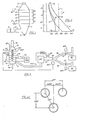
- a duct 10 conducts hot exhaust gas, such as flue gas drawn from a boiler stack (not shown) by blower B, to a bottom plenum or chamber 11.
- the flue gas passes upwardly through one or more heat exchange units, such as the four units indicated at 12, 13, 14 and 15, thence into an upper plenum or chamber 16 and out a stack 17.
- the flue gas velocity is arranged to be 30-40 feet per second within the heat exchange units, and a gas pressure drop of the order of 1 1/2 to 2 inches of water is arranged to occur across the heat exchange units.
- a fluid to be heated which typically will be water or air, is shown introduced into the uppermost heat exchange unit at 20, understood to flow downwardly through successive ones of the heat exchange units, and to exit at 21.
- the hot exhaust gas is flue gas from a boiler.
- the flue gas will be cooled to some extent as it travels upwardly through the unit, and that the water will be heated to some extent as it travels downwardly through the unit.
- the range of elevations within which significant gas cooling and water heating occur is shown divided into four zones Z1 to Z4. The four zones are shown for simplicity of explanation as corresponding to the vertical ranges of the four heat recovery units.
- Fig. 2 illustrates the variations of flue gas and water temperatures in typical practice of the invention to heat water, with the temperatures plotted against vertical elevation.
- G I assumed input temperature
- the gas temperature plot in Fig. 2 should be understood to be approximate, and in general to depict for any elevation the lowest temperature to which substantial portions of the gas are lowered at that elevation.
- some portions of the flue gas such as portions near or on a tube may have the temperature G 2 at which sulfuric acid is forming, while other portions of the gas at the same elevation but at greater distances from any tube may be hotter and not yet experiencing condensation.
- water assumed to have an input temperature W l of 55°F at the top of the heat exchanger is heated to an output temperature W 0 of 180°F by the time it reaches the bottom of the heat exchanger, as indicated by curve W.
- the ordinate scale in Fig.1 is shown divided into the four zones Z1 to Z4.
- a vertical dashed line F at 250°F indicates a typical temperature G 2 at which sulfuric acid forms in typical flue gas obtained from burning No. 6 fuel oil.
- the prior art has taught that flue gas temperature always should be maintained amply above that level in order to avoid production of any sulfuric acid.
- zone Z3 As the flue gas is cooled below 250°F, a typical dew point for sulfur trioxide, sulfuric acid forms in zone Z3. If zone Z3 were the uppermost zone in the system, the condensed sulfuric acid would slightly wet heat exchange surfaces in zone Z3, and particulate matter would build upon those slightly wetted surfaces.
- the sulfur trioxide condenses to form sulfuric acid in the assumed example, as gas travel through zone Z3 cools the gas substantially below the acid dew point. At some level within zone Z3 most or all of the sulfuric acid which will be condensed, will have condensed. Just above that level there is believed to be a range of elevations, indicated generally by bracket R in Fig.
- the tubes within the heat exchange units are arranged in successive rows which are horizontally staggered relative to each other, so that a drop of condensate falling from one tube tends to splash on a tube below.
- a double form of cleaning of the flue gas occurs, from the combined scrubbing of the gas as it passes through the falling rain of condensate, plus the tendency of the particulate matter to temporarily and lightly adhere to the wetted tubes until condensate washes it away.
- the water temperature reaches the water vapor dew point (120°F) at substantially the same elevational level where the flue gas temperature reaches the sulfuric acid dew point (250°F), and further, that the level occurs substantially at the vertical mid-level of the heat exchanger. Those precise relationships are by no means necessary.
- curve D is a plot of the difference between flue gas temperature and water temperature versus elevational level in the heat exchanger unit.
- the temperature difference at a given level has an important bearing, of course, on the amount of heat transfer which occurs at that level. It is important to note that near the bottom portions of the heat exchanger unit, in zones Zl and Z2, where there is maximum difference between gas temperature and water temperature and hence a maximum potential for effective heat transfer, the amount of heat transfer which actually occurs is further increased because the heat exchange tube surfaces in those zones are maintained wet by falling condensate.
- the flue gas exit temperature measured in chamber 16 or stack 17 in Fig. 1, for example, will be less than the flue gas water vapor dew point temperature of say 120cF, but in some systems the exit temperature at such a location may exceed that dew point to some extent, without departing from the invention. If the heat exchanger tube and housing geometry allows some quantum of flue gas to pass through the unit with only modest cooling, that quantum will mix in chamber 16 with flue gas which has been cooled sufficiently to condense large amounts of water, and tend to raise the average or mixed temperature in chamber 16, in the same manner that by-passing some flue gas around the heat exchanger and admitting it to chamber 16 would raise the average temperature in that chamber.
- the method of the invention comprises simultaneous recovery of both sensible and latent heat from a hot exhaust gas containing water vapor, a condensable corrosive constituent (sulfur trioxide) and particulate matter, and removal of substantial amounts of the particulate matter and condensed corrosive constituent from the gas, by passing the gas through a gas passage of a heat exchanger, simultaneously passing a fluid cooler than the exhaust gas through a second passage of the heat exchanger in heat exchange relationship with the gas passage, with the flow rates of the gas and fluid arranged in relation to the heat transfer characteristics of the heat exchanger so that continuous condensation of water vapor and the corrosive constituent occurs, providing falling droplets which capture and wash away portions of the particulate matter and condensed corrosive constituent.
- the invention advantageously can use cold water or air, and indeed, efficiency increases the colder the input fluid is, with more condensation occurring and more latent heat being extracted from the exhaust gas.
- Tests to date have indicated that with a gas velocity of the order of 30-40 feet per second, provision of sufficient heat exchange surface area will enable one to lower the temperature of the fluid being heated, be it water or air.
- the advantageous effect which very substantial water condensation has on heat transfer has been illustrated by operating one form of the invention under two sets of operating conditions.
- the unit was first operated with flue gas produced by burning No. 2 fuel oil, with particular inlet and outlet temperatures and flow rates of flue gas and water.
- the heat recovered was measured to be approximately 1, 000,000 Btu per hour, and condensate flowed from the unit at approximately one-half gallon per minute.
- flue gas produced by burning natural gas was used.
- the natural gas can be and was burned with less excess air, and due to the greater hydrogen content of the natural gas, the flue gas contained a greater amount of moisture.
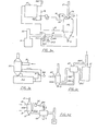
- flue gas is drawn from the conventional stack 30 of boiler 31 past one or more damper valves by an induced draft blower B driven by blower motor BM, to supply the flue gas to the bottom plenum of the heat exchange unit HX, and cooled flue gas exits via fiberglass hood 16 and fiberglass stack 17 to atmosphere.
- the use of a fiberglass stack to resist corrosion is not per se new.
- Cool water from the bottom of hot water storage tank ST, from a cold water supply line SL and/or from a water main WM, is pumped through the heat exchange unit HX by circulator pump CP, and heated water from the heat exchanger is pumped into storage tank ST near its top. Hot water is drawn from the top of the storage tank via line HW for any of a variety of uses.
- Make-up water for boiler 31 can be supplied from tank ST, of course, or directly from unit HX.
- a conventional thermal sensor TS senses outgoing flue gas temperature and operates a conventional positioner PV1, which closes damper valve DV1 to decrease or terminate passage of hot flue gas to the heat exchanger.
- a second positioner PV2 also responsive to thermal sensor TS is shown connected to operate damper valve DV2, which can open when stack 17 temperature climbs too high, to mix cool ambient air with the flue gas, thereby to prevent temperature within the heat exchanger from exceeding a value (e.g.500°F) deemed dangerous for the corrosion-protective coatings.
- a value e.g.500°F
- preventing a temperature rise which would damage the corrosion-protection coatings can instead be done by using a conventional non-condensing heat exchanger to cool the exhaust gas to a safe operating temperature before the exhaust gas is passed through the water-condensing heat exchanger.
- a spray manifold SP carrying a plurality of nozzles is operative to spray water down through heat exchanger HX when valve V is opened, to wash away any deposits which might have built up on heat exchanger tubes. Because operation in the water condensing mode ordinarily functions to keep the tubes clean, operation of such a spray can be quite infrequent, and in some applications of the invention provision of such a spray means may be deemed wholly unnecessary. In certain applications, such as where particulate removal is deemed particularly important, valve V can be opened to permit a continuous spray, to augment the "rain" caused by water vapor condensation.
- the condensation entraps paper particles as well as other particulate matter, with incipient tendencies of causing severe corrosion and clogging, but control of flow rates in relation to temperatures in accordance with the invention, so that large amounts of water vapor are condensed at a higher elevation within the heat exchanger causes a rain to wash away the sulfuric acid- particulate matter composition. And as in the case of water heating applications, use of the water condensing mode increases the amount of sensible heat recovered, provides recovery of significant amounts of latent heat, and maintains heat exchange surfaces wet and clean to improve heat transfer.
- the hot exhaust gas supplied by a furnace or other device may have an initial temperature substantially exceeding that (e. g. 550°F) to which the Teflon protective coatings can safely be exposed, but that by no means rules out use of the invention in such applications.
- exhaust gas emanating from an industrial furnace IF and assumed to have a temperature of 950°F is passed to a conventional prior art air preheater AP which need not have corrosion-protective coatings.
- the air preheater AP also receives air from a heat exchanger HXA operated according to the invention in the water condensing mode. Heat exchanger HXA heats ambient air up to a temperature (e. g.
- a conventional non-condensing heat exchanger can be used to lower an exhaust gas temperature below the material limit operating temperature of the condensing heat exchanger in numerous applications where, unlike Fig. 3c, the fluid heated by the condensing heat exchanger does not pass through the conventional heat exchanger, and that fluid heated by the condensing heat exchanger can be water, of course, rather than air.
- the fluid heated by the condensing heat exchanger does not pass through the conventional heat exchanger, and that fluid heated by the condensing heat exchanger can be water, of course, rather than air.
- 3d exhaust gas from the stack of furnace F2 passes through a conventional air preheater AH, and thence through a water-condensing heat exchanger HXB operated according to the invention, to heat water circulated through unit HXB via lines 20, 21.
- a thermal sensor TS2 senses the gas temperature entering unit HXB and controls the flow of the fluid being heated by the conventional heat exchanger AH, increasing that flow to decrease the temperature of the gas entering unit HXB should it begin to rise above a desired value.
- the thermal sensor is depicted as controlling file speed of a blower motor BM via a motor controller MC, but it will be apparent that the thermal load imposed on unit AH may be varied in other ways in various applications, such as by positioning of a damper valve which controls flow of the cooler fluid through unit AH. While Figs. 3c and 3d illustrate uses of water-coridensing heat exchangers with conventional or prior art non-condensing heat exchangers, it is to be understood that a water-condensing heat exchanger and a non-condensing heat exchanger can be combined in the sense of being mounted adjacent each other or on a common support so as to shorten or eliminate ducting between the two heat exchangers.
- a water-condensing heat exchanger installed to receive flue gas which has passed through the conventional air preheater may be used to heat ambient air and supply it to the conventional air preheater at a sufficiently high temperature that no condensation or corrosion will occur in the conventional air preheater.
- Many industrial boilers use economizers to heat boiler feed water, and in many cases such boilers require 50-75% cold makeup water.
- the water-condensing heat exchanger of the invention may be installed to receive the flue gas exiting from the economizer at say 350 c F, which normally has been expelled through a stack, to heat the boiler makeup water before the water goes to the deaerator associated with the boiler.
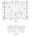
- FIGs. 4a and 4b illustrate one exemplary module.
- Outwardly facing channel-shaped members 40, 41 of formed sheet steel form rigid side members, and carry bolt-holes 42, 42 in upper and lower channel flanges, allowing as many modules as may be needed to provide a desired heat transfer surface area to be stacked vertically atop one another and bolted together.
- the unit includes two tube sheets or end plates 43, 44 which are bolted to the side members 40, 41, as by means of bolts 45,45.
- each tube sheet is provided with four outwardly-extending flanges along its four respective edges, such as flanges 43a to 43d shown for tube sheet 43 in Fig.4b.
- each tube sheet carries 8 rows of holes, with 18 holes in each row, with the holes in alternate rows staggered as shown, and 144 tubes 48, 48 extend between the two tube sheets, extending about 2.81 inches outside each tube sheet.
- the outside diameter of each tube, with its corrosion-protection coating was 1. 22 inches
- the tubes in each row were spaced on 1. 75 inch centers
- the vertical distance between tube centers was 1. 516 inch, as shown in Fig.
- each tube has a surface area inside the module of 1. 33 sq. ft., providing a heat transfer surface for all 144 tubes of 190. 8 sq. ft. within a volume of approximately 13. 5 cu.ft.
- Each tube comprised a Type L (0. 050 in. wall thickness) copper water tube of nominal 1 inch inside diameter having an actual inside diameter of 1.
- Tube sheet 43 carries a 60 mil layer of TFE Teflon not only on its inside surface visible in Fig. 4b, but also on the upper surface of its upper flange 42a, the lower surface of its lower flange 42d, and the leftside and rightside (in Fig.
- Channel shaped side members 40, 41 carry a 60 mil layer of TFE Teflon not only on their vertical (in Fig. 4b) inside surfaces 40a, 41a, but also on the top surfaces 40b, 41b of their upper flanges and the lower surfaces 40c, 41c of their lower flanges.
- Teflon-to-Teflon joints exist between the channel-shaped side members 40, 41 and the side flanges of the tube sheets where they are bolted together.
- the Teflon coverings for the tube sheets and side members are formed by cutting Teflon sheet material to size, and then heating it.
- Three modules of the type described were vertically stacked, to provide 572 sq.ft. of heat transfer surface area, in a system intended to handle a flue gas flow of 9660 lbs. per hour, with a gas mass flow of 0.762 lbs. per second per sq. ft. of open gas passage area.
- the velocity of the flue gas within the heat exchanger should be high enough to provide turbulent flow to insure good heat transfer, but not so high as to cause abrasion of the Teflon coatings or to blow large amounts of condensate up the stack.
- Velocities within the range of 30-40 feet per second have proven suitable in the unit described. It should be recognized that smaller or larger velocities may be quite suitable in many applications of the invention.
- the corrosion-prevention covering has been applied to the heat exchanger tubes by heat-shrinking, a technique generally well known.After buffing a straight section of copper (or aluminum) tube to clean it and to remove any burrs, Teflon FEP tubing approximating the length of the metal is slid over the metal tube. Next, a short end length portion of several inches of the metal tube, covered with Teflon tubing extending slightly beyond the end of the metal tube, is immersed in a tank of propylene glycol heated to 330°F. Only the short length is immersed and heated for several seconds, causing the Teflon tubing to shrink tightly about the short length of immersed metal tube.
- Teflon tubing Only after the short end length of Teflon has shrunk, is it safe to further immerse the assembly; otherwise heated propylene glycol might enter between the Teflon tubing and the exterior surface of the metal tube.
- the metal tube-Teflon tubing assembly may be lowered further into the propylene glycol bath to its full length, typically at a rate of about 1 foot per second. Because the heated propylene glycol flows inside the metal tube as well as surrounding the outside of he Teflon tubing, uniform heating and shrinking occurs. After the full length has been immersed for 2-4 seconds the assembly may be removed from the tank.
- the Teflon tubing increases in length as it shrinks in diameter, so that after heat shrinking it extends beyond the ends of the metal tubing, and may be cut off.
- the holes in each steel tube sheet each have a diameter (e. g. 1. 28) inch which exceeds the outside diameter of the covered tubes by 0.060 in. (60 mils) the thickness of the Teflon covering in the tubes, but the holes punched in the Teflon tube sheet are each substantially smaller,.e. g. 0. 625 inch in diameter, as is shown in Fig. 7a, where portions of the TFE Teflon sheet 101 initially cover portions of a hole in tube sheet 43.
- the edge of the hole in the tube sheet is preferably made slightly beveled on the inside of the tube sheet, as best seen at 102 in Fig. 7b, but flat or perpendicular on the outside of the tube sheet, as shown at 103.
- a tapered electrically heated tool 104 is used to extrude portions of the Teflon sheet through the holes in the steel tube sheet.
- the metal tool 104 has a rounded nose small enough (e. g. 0. 375 inch) to enter a 0. 627 inch hole in the Teflon sheet 101, and rearwardly from the nose the tool tapers gradually upwardly to a constant diameter d equalling the outside diameter of the Teflon-covered tubes to be used.
- the tool is heated to 780°F.
- tool 104 With the tool nose inserted into a hole in the Teflon sheet, as shown in Fig. 7a, tool 104 is urged lightly against the Teflon sheet by an air cylinder (not shown). As the tool heats the edges of the hole in the Teflon, the tool is gradually advanced by the constant force from the air cylinder. As the constant diameter portion of the tool nears the Teflon sheet, tool advancement tends to slow or stop until the Teflon is further heated, and then the tool suddenly pushes through, after which a further tool advancement is prevented by a stop (not shown). The Teflon then lines the hole in the metal tube sheet with a 30 mil thick lining, with some Teflon extending on the outside of the tube sheet.
- the tool is held extending through the tube sheet for about 15 seconds while Teflon on the outside of the tube sheet further heats, and then the tool is rapidly retracted out of the tube sheet.
- Retraction causes a collar or bead having a diameter exceeding that of the hole in the tube sheet to be formed around the hole on the outside of the tube sheet, as indicated at 105 in Fig. 7b.
- the rounding or beveling of the tube sheet hole on its inside edge helps prevent the Teflon sheet from cracking as the tool is forced into the hole.
- the perpendicular edge of the hole on the outside of the sheet tends to impede inward flow of soft Teflon as the tool is retracted, and consequent forming of the collar or bead 105.
- a plug having the same outside diameter as be Teflon-covered tube to be used is inserted into the tube sheet hole through which Teflon has been extruded, to prevent any decrease in diameter.
- Cylindrical plugs formed of many different materials can be used, but short lengths of Teflon-covered copper or aluminum tubing cut from a tube covered as previously described are preferred.
- Fig. 7b can be deemed to illustrate a tube sheet hole carrying such a plug, if item 48 is deemed to be a short length of Teflon-covered tube.
- the plug in the proper hole in tube sheet 44 is removed by another person at the tube sheet 44 end of the module, and the entry end of the tube can be pushed through the hole in tube sheet 44 to its final position, with two persons at opposite ends of the module pushing and pulling on the tube. That it generally requires two strong persons to slide the tube when it is installed in both tube sheets indicates the tightness of the fit which occurs. Hydraulic rams or like can be used, of course, to facilitate insertion of the tubes. While insertion of a tube can take place over a time period of several (e. g. 3) minutes, use of less time tends to be advantageous.
- exhaust gas is conducted via inlet duct 50 into the lower plenum 51 of a water-condensing heat exchanger for upward passage between nests of FEP Teflon-covered aluminum tubes into fiberglass upper plenum 56 and out fiberglass stack 57.
- Each tube extends through the two tube sheets supporting its ends.
- An inlet air duct 52 covers one end of an uppermost group of tubes 62.
- the other ends of tube group 62 and the ends of a next lower group of tubes 63 are shown covered by hood or cover 63, so that air exiting'from tube group 62, rightwardly in Fig. 5a, is returned through tube group 64, leftwardly in Fig. 5a.
- FIGs. 5a and 5b illustrate a system in which air passes through the heat exchanger seven times, for sake of illustration. In actual practice one to five passes ordinarily has been deemed adequate.
- the insides of the tube sheets, slide members, and the covers, and the inside of plenum 51, are lined with corrosion-protection lining, as in the case of water-heating exchangers. Though not shown in Figs. 5a and 5b, it will be apparent at this point, that if desired, spray nozzles can be provided inside the air-heating heat exchanger of Figs. 5a and 5b for the same purposes as were mentioned in connection with the water-heater heat exchanger of Fig. 3a.
- a water-condensing heat exchanger BHX arranged to heat both combustion air and boiler make-up water comprises six vertically-stacked modules 61-66.
- Ambient or room air enters module 63 and the upper half of module 62 through an inlet duct 67, makes one pass across the heat exchanger, and is directed by return plenum or hood 68 back through the tubes in module 61 and the top half of module 62, into ducting 70 which connects to the inlet of a forced draft fan FDF.
- the upper three modules 64-66 of heat exchanger BHX preheat boiler makeup water The water flows from a cold water main source 71 to an inlet manifold IM which distributes the water laterally across the top row of tubes in module 66 in seven water flow paths which progress horizontally and vertically through modules 64-66 to outlet manifold OM. Flue gas enters lower plenum 72 of heat exchanger BHX through duct 73, and passes upwardly through modules 61 to 66 in succession, into fiberglass upper plenum 74 and thence out fiberglass stack 75.
- Flue gas is pulled from the stacks of the two boilers by a single induced-draft fan IDF, with the amount of flue gas being drawn from each boiler being controlled by a respective damper, 76 or 77, which is controlled by a respective modulating positioner, MP1 or MP2, and the modulating positioners are each controlled by the load on a respective boiler using conventional pneumatic control signals from a conventional boiler control system.
- the modulating positioners are set so that under full load conditions dampers 76 and 77 are fully open and all of the flue gas produced by each boiler is directed to heat exchanger BHX. If fan IDF were to pull more flue gas than both boilers are producing, either the boiler excess air would increase or outside air would be drawn down the boiler stacks, in either case decreasing efficiency. To avoid those problems, dampers 76 and 77 decrease the amount of flue gas drawn from each boiler when its load is decreased.
- the modulating positioners MP1 and MP2 close their respective dampers when their associated boilers are shut down, and they are interlocked with induced-draft fan IDF to close their dampers if fan IDF is not running, and then all flue gas will exit through the boiler stacks.
- Damper 82 in duct 81 regulates the total amount of flue gas going to heat exchanger BHX depending upon the combustion air and makeup water demand rates. Damper 82 is modulated to control the temperature of the pre-heated makeup water exiting from exchanger BHX at a desired set point (180°F), by sensing the water temperature at its exit from unit BHX to operate a proportional servomotor SM1.
- Damper 82 is normally fully open, allowing all of the flue gas being produced by the boilers to pass through heat exchanger BHX, but during rapid transient conditions, or during periods of reduced makeup water requirements, more heat may be available from the flue gas than can be utilized to preheat the combustion air and makeup water, in which case the temperature of the water exiting from heat exchanger BHX will start to rise, but servomotor SM1 then will begin to close damper 82 to maintain the exit temperature of the water from heat exchanger BHX at the desired setpoint. Since the flue gas passed first through the lower air-heating section and then through the water-heating section, where the input water temperature (e. g. 46°F) is lower than the input air temperature (e. g.
- a further modulating damper 83 ahead of the induced draft fan operates to limit the temperature of flue gas by admitting sufficient room air to mix with the flue gas that the inlet temperature of the flue gas to heat exchanger BHX does not exceed the safe operating temperature (e. g. 500°F) for the Teflon corrosion-prevention materials which line heat exchanger BHX.
- Temperature sensor TS3 senses the flue gas temperature at the exit of fan IDF to control the position of damper 83 via servomotor SM2. If the temperature of the flue gas is 500°F or less, damper 83 will be fully closed.
- Drain line D at the bottom of unit BHX includes a transparent section of tubing 85 through which the color of the condensate may be observed.
- No.6 oil is used as boiler fuel, the condensate is black due to the large amount of particulate matter and S0 3 removed from the flue gas, while use of natural gas as boiler fuel provides a virtually clear condensate due to the very small amounts of particulate matter in the flue gas.
- a dial thermometer DT1 located in stack 75 indicates flue gas exit temperature, which typically varies between 90°F and 200°F, depending upon boiler load.
- Temperature sensor TS4 also located at stack 75 serves to shut down the heat recovery system by closing damper 82 if the flue gas exit temperature should exceed 200°F.
- Simple BTU computers receive water and air temperature and flow rate signals and compute the amounts of heat recovered. At an average steam load of 30,000 pounds per hour, the combined amount of heat recovered is 3,468,000 Btu per hour. Prior to use of the condensing heat exchanger the average steam load of 30,000 pounds per hour required an average fuel consumption of 148.4 gallons per hour of No.6 fuel (148,000 Btu per gallon) with a boiler efficiency of 80%. Utilizing the water-condensing heat exchanger 29.3 gallons per hour of fuel are saved, a savings of 20%.
- the lower housing (11 in Fig. 1, for example) comprises a simple steel sheet housing completely lined with 60 mil TFE Teflon, with its flanges also covered with Teflon in generally the same manner as in the tube modules.
- the lower housing may take a variety of different shapes in various applications.
- An upper section (e. g. 1 foot) of drain D which connects to the bottom of the lower housing is also preferably formed of TFE Teflon tubing.
Landscapes
- Engineering & Computer Science (AREA)
- Physics & Mathematics (AREA)
- Thermal Sciences (AREA)
- Mechanical Engineering (AREA)
- General Engineering & Computer Science (AREA)
- Chemical & Material Sciences (AREA)
- Oil, Petroleum & Natural Gas (AREA)
- General Chemical & Material Sciences (AREA)
- Analytical Chemistry (AREA)
- Chemical Kinetics & Catalysis (AREA)
- Health & Medical Sciences (AREA)
- Biomedical Technology (AREA)
- Environmental & Geological Engineering (AREA)
- Heat-Exchange Devices With Radiators And Conduit Assemblies (AREA)
- Treating Waste Gases (AREA)
- Chimneys And Flues (AREA)
- Vaporization, Distillation, Condensation, Sublimation, And Cold Traps (AREA)
- Treatment Of Fiber Materials (AREA)
- Exhaust Gas After Treatment (AREA)
Priority Applications (1)
| Application Number | Priority Date | Filing Date | Title |
|---|---|---|---|
| AT85101559T ATE49469T1 (de) | 1981-04-09 | 1981-10-15 | Verfahren zur herstellung eines waermeaustauschers und waermeaustauscher gemaess diesem verfahren. |
Applications Claiming Priority (2)
| Application Number | Priority Date | Filing Date | Title |
|---|---|---|---|
| US25229781A | 1981-04-09 | 1981-04-09 | |
| US252297 | 1981-04-09 |
Related Parent Applications (1)
| Application Number | Title | Priority Date | Filing Date |
|---|---|---|---|
| EP81304807.1 Division | 1981-10-15 |
Publications (3)
| Publication Number | Publication Date |
|---|---|
| EP0155498A2 true EP0155498A2 (fr) | 1985-09-25 |
| EP0155498A3 EP0155498A3 (en) | 1987-06-16 |
| EP0155498B1 EP0155498B1 (fr) | 1990-01-10 |
Family
ID=22955429
Family Applications (2)
| Application Number | Title | Priority Date | Filing Date |
|---|---|---|---|
| EP85101559A Expired - Lifetime EP0155498B1 (fr) | 1981-04-09 | 1981-10-15 | Procédé de fabrication d'un échangeur de chaleur et échangeur de chaleur produit comme tel |
| EP81304807A Expired - Lifetime EP0063195B1 (fr) | 1981-04-09 | 1981-10-15 | Procédé et dispositif pour le traitement des gaz d'échappement |
Family Applications After (1)
| Application Number | Title | Priority Date | Filing Date |
|---|---|---|---|
| EP81304807A Expired - Lifetime EP0063195B1 (fr) | 1981-04-09 | 1981-10-15 | Procédé et dispositif pour le traitement des gaz d'échappement |
Country Status (6)
| Country | Link |
|---|---|
| US (1) | US4557202A (fr) |
| EP (2) | EP0155498B1 (fr) |
| JP (2) | JPS57171422A (fr) |
| AT (2) | ATE50920T1 (fr) |
| CA (1) | CA1168593A (fr) |
| DE (2) | DE3177162D1 (fr) |
Cited By (3)
| Publication number | Priority date | Publication date | Assignee | Title |
|---|---|---|---|---|
| EP0321452A1 (fr) | 1981-04-09 | 1989-06-21 | Heat Exchanger Industries, Inc. | Procédé de récupération de chaleur dans un gaz d'échappement |
| ES2065229A2 (es) * | 1991-09-06 | 1995-02-01 | Behr Gmbh & Co | Cambiador de calor. |
| EP0715122A3 (fr) * | 1994-11-30 | 1997-02-12 | Hitachi Shipbuilding Eng Co | Appareil de traitement des gaz de fumée pour une installation d'incinération |
Families Citing this family (49)
| Publication number | Priority date | Publication date | Assignee | Title |
|---|---|---|---|---|
| EP0102770A3 (fr) * | 1982-08-10 | 1987-05-27 | Heat Exchanger Industries, Inc. | Méthode et appareil pour le traitement de gaz d'échappement |
| FR2548036B1 (fr) * | 1983-06-30 | 1985-10-18 | Supratherm Sarl | Procede d'epuration de gaz chauds par condensation |
| US4582122A (en) * | 1983-08-10 | 1986-04-15 | Linde Aktiengesellschaft | Efficient waste heat recovery process from sulfur containing flue gas |
| EP0150694A1 (fr) * | 1984-01-27 | 1985-08-07 | Jacob Weitman | Dispositif de récupération de chaleur |
| DE3416947A1 (de) * | 1984-05-08 | 1985-11-14 | Reichart, Johannes, 7312 Kirchheim | Verfahren und vorrichtung zur reinigung von rauchgasen in feuerungsanlagen |
| SE448257B (sv) * | 1985-01-23 | 1987-02-02 | Ragn Sellsforetagen Ab | Sett och anordning for att genom kylning rena rokgaser fran sopforbrenning samt dervid utvinna vermeenergi |
| DE3507882A1 (de) * | 1985-03-06 | 1986-09-11 | Sigri GmbH, 8901 Meitingen | Verfahren zum loesen von salzkrusten in einem waermeaustauscher |
| US4928749A (en) * | 1985-05-08 | 1990-05-29 | Industrial Energy Corporation | Heat exchange recovery method |
| US4930571A (en) * | 1985-05-08 | 1990-06-05 | Industrial Energy Corporation | Heat recovery apparatus |
| US4726353A (en) * | 1985-08-01 | 1988-02-23 | Raytheon Company | High condensing recuperative furnace |
| US4848314A (en) * | 1985-09-20 | 1989-07-18 | Carrier Corporation | Condensing furnace |
| US4807588A (en) * | 1986-07-02 | 1989-02-28 | Carrier Corporation | Water permeable heat exchanger for condensing furnace |
| US4681257A (en) * | 1986-08-12 | 1987-07-21 | Turner Reginald R | Hot-water-furnace supplemental heater |
| DE3639966A1 (de) * | 1986-11-22 | 1988-06-01 | Bergwerksverband Gmbh | Wirbelschichtreaktor aus edelstahlgussgehaeuse |
| US5020452A (en) * | 1989-10-11 | 1991-06-04 | Murya, Inc. | Thermal remediation apparatus and method |
| US5401480A (en) * | 1990-08-14 | 1995-03-28 | Energy Conservation Partnership Ltd. | Removal of sulfur and nitrogen oxides from flue gases |
| US5273727A (en) * | 1991-07-16 | 1993-12-28 | Energy Conservation Partnership, Ltd. | Flue gas purification and production of dry ammonium bisulfites and bisulfates |
| US5230870A (en) * | 1992-05-26 | 1993-07-27 | Johnson Arthur F | Method for converting noxious pollutants from flue gas into merchantable by-products |
| US5384106A (en) * | 1991-07-16 | 1995-01-24 | Energy Conservation Partnership Ltd. | Method for removing pollutants from a gas stream using a fractional condensing heat exchanger |
| TW245651B (en) * | 1994-02-24 | 1995-04-21 | Babcock & Wilcox Co | Black liquor gasifier |
| US5480619A (en) * | 1994-06-28 | 1996-01-02 | The Babcock & Wilcox Company | Regenerative scrubber application with condensing heat exchanger |
| US5534230A (en) * | 1994-07-05 | 1996-07-09 | The Babcock & Wilcox Company | Segmented heat exchanger flue gas treatment |
| US5510087A (en) * | 1994-07-05 | 1996-04-23 | The Babcock & Wilcox Company | Two stage downflow flue gas treatment condensing heat exchanger |
| US5567215A (en) * | 1994-09-12 | 1996-10-22 | The Babcock & Wilcox Company | Enhanced heat exchanger flue gas treatment using steam injection |
| CA2157841A1 (fr) * | 1994-09-12 | 1996-03-13 | Gregory T. Bielawski | Controle de la toxicite de l'air et extraction des vapeurs de gaz de combustion au moyen d'echangeurs de chaleur pour laveur d'air |
| SE9504064L (sv) * | 1994-11-30 | 1996-05-31 | Babcock & Wilcox Co | Återvinning och utnyttjande av restprodukter i sulfatprocessen |
| US5603909A (en) * | 1995-08-03 | 1997-02-18 | The Babcock & Wilcox Company | Selective catalytic reduction reactor integrated with condensing heat exchanger for multiple pollutant capture/removal |
| US5792238A (en) * | 1995-12-01 | 1998-08-11 | The Babcock & Wilcox Company | Fine-particulate and aerosol removal technique in a condensing heat exchanger using an electrostatic system enhancement |
| US5676715A (en) * | 1996-02-13 | 1997-10-14 | The Babcock & Wilcox Company | Key advanced linear kinetic absorber system particulate arresting device |
| US5826518A (en) * | 1996-02-13 | 1998-10-27 | The Babcock & Wilcox Company | High velocity integrated flue gas treatment scrubbing system |
| DE19654736C2 (de) * | 1996-12-30 | 1999-08-05 | Hans Dieter Treptow | Abdichtungselement zur Abdichtung der Rohrplattenrückseite und der Rohrenden gegen das Medium im Mantelraum (Raum um die Rohre) in Wärmetauschern |
| FR2807826B1 (fr) * | 2000-04-13 | 2002-06-14 | Air Liquide | Echangeur vaporisateur-condenseur du type a bain |
| CA2430041A1 (fr) * | 2003-05-26 | 2004-11-26 | Eugene I. Moody | Chaudiere a liquide atomise |
| FI120162B (fi) * | 2005-02-17 | 2009-07-15 | Foster Wheeler Energia Oy | Leijupetikattilalaitos ja menetelmä rikkipitoisen polttoaineen polttamiseksi leijupetikattilalaitoksessa |
| US7716850B2 (en) * | 2006-05-03 | 2010-05-18 | Georgia-Pacific Consumer Products Lp | Energy-efficient yankee dryer hood system |
| DE102007020145A1 (de) * | 2006-05-23 | 2007-11-29 | Bayer Materialscience Ag | Vorrichtung zum Abkühlen von Gasen (Quenche) unter Bildung eines korrosiven Kondensats |
| US20100139533A1 (en) * | 2008-12-05 | 2010-06-10 | Jin-shin Park | Movable integrated cremation device |
| US8544527B2 (en) | 2008-12-23 | 2013-10-01 | Uop Llc | Method to reduce condensation in a cooling zone of a continuous catalyst regeneration system |
| JP5602308B2 (ja) * | 2011-07-14 | 2014-10-08 | 三菱重工業株式会社 | ガス冷却器、ガス化炉及び炭素含有燃料ガス化複合発電装置 |
| US10016722B2 (en) * | 2014-11-12 | 2018-07-10 | Demist Tech. Inc | Thermal power plant exhaust purification device |
| CN106017154B (zh) * | 2016-06-25 | 2018-08-03 | 浙江鼎诚环保科技有限公司 | 一种用于烟气脱硫的换热设备 |
| US10301208B2 (en) * | 2016-08-25 | 2019-05-28 | Johns Manville | Continuous flow submerged combustion melter cooling wall panels, submerged combustion melters, and methods of using same |
| CN106556025A (zh) * | 2016-11-29 | 2017-04-05 | 无锡市锡源锅炉有限公司 | 一种锅炉烟气冷凝余热回收装置 |
| JP6890318B2 (ja) * | 2017-04-18 | 2021-06-18 | 国立研究開発法人農業・食品産業技術総合研究機構 | 除塵システム及び除塵方法 |
| US11202983B2 (en) * | 2017-11-08 | 2021-12-21 | Btu International, Inc. | Devices, systems and methods for flux removal from furnace process gas |
| US10245546B1 (en) | 2018-08-22 | 2019-04-02 | H & H Inventions & Enterprises, Inc. | Exhaust gas purification method and system |
| JP2020078762A (ja) * | 2018-11-10 | 2020-05-28 | Aca株式会社 | 排ガスの有害物質除去装置 |
| CN109621622A (zh) * | 2018-11-30 | 2019-04-16 | 中国地质大学(武汉) | 一种旋风冷凝装置 |
| US12141508B2 (en) | 2020-03-16 | 2024-11-12 | Washington University | Systems and methods for forming micropillar array |
Family Cites Families (28)
| Publication number | Priority date | Publication date | Assignee | Title |
|---|---|---|---|---|
| US2022173A (en) * | 1931-02-18 | 1935-11-26 | Clive M Alexander | Heat transfer apparatus |
| US2816739A (en) * | 1954-03-03 | 1957-12-17 | Schutte & Koerting Co | Tube and tube sheet assembly |
| US2856905A (en) * | 1955-04-04 | 1958-10-21 | Oxy Catalyst Inc | Heat generating and exchanging device |
| LU35737A1 (fr) * | 1957-01-30 | |||
| GB972129A (en) * | 1960-02-19 | 1964-10-07 | English Electric Co Ltd | Improvements in and relating to tubular steam condensers |
| FR1390998A (fr) * | 1963-12-17 | 1965-03-05 | Pechiney Saint Gobain | Appareils séparateurs par condensation |
| US3405759A (en) * | 1966-11-08 | 1968-10-15 | Combustion Eng | Method of and means for controlling the external temperatures of fired processing equipment |
| FR2050325B1 (fr) * | 1969-07-23 | 1973-12-21 | Chausson Usines Sa | |
| US3791351A (en) * | 1972-06-30 | 1974-02-12 | Rohm & Haas | Desuperheater |
| US3820590A (en) * | 1973-02-28 | 1974-06-28 | B Littman | On-line adaptive control of a heat exchanger |
| FR2232423B1 (fr) * | 1973-06-08 | 1976-04-23 | Pont A Mousson | |
| US3906874A (en) * | 1973-08-30 | 1975-09-23 | Nutmeg Sanitation Inc | Mobile furnace vehicle |
| JPS5715634B2 (fr) * | 1975-02-07 | 1982-03-31 | ||
| DE2610817A1 (de) * | 1975-03-21 | 1976-09-30 | Froehlich Air Ag | Rohrwaermetauscher und verfahren zu dessen herstellung |
| US4044820A (en) * | 1976-05-24 | 1977-08-30 | Econo-Therm Energy Systems Corporation | Method and apparatus for preheating combustion air while cooling a hot process gas |
| US4134727A (en) * | 1976-08-12 | 1979-01-16 | Betz Laboratories, Inc. | Aqueous solution of sodium metasilicate and N-aminoethyl ethanolamine as a cold-end additive |
| CH616224A5 (en) * | 1977-04-14 | 1980-03-14 | Alusuisse | Heat exchanger. |
| US4125152A (en) * | 1977-09-19 | 1978-11-14 | Borg-Warner Corporation | Scale resistant heat transfer surfaces and a method for their preparation |
| DE2801328C2 (de) * | 1978-01-13 | 1987-04-30 | Krupp Koppers GmbH, 4300 Essen | Verfahren und Vorrichtung zur Kühlung von Koksofengas |
| SE7808367L (sv) * | 1978-08-03 | 1980-02-04 | Ostbo John D B | Anordning vid vermevexlare |
| JPS5572792A (en) * | 1978-09-05 | 1980-05-31 | Allied Air Prod | Condenser |
| DE2841026C2 (de) * | 1978-09-21 | 1983-03-10 | A. Ahlström Oy, 29600 Noormarkku | Verbrennungsvorrichtung |
| DE2908546A1 (de) * | 1979-03-05 | 1980-09-18 | Reininger Geb Strey | Gebaeudeheizeinrichtung |
| DE2926663A1 (de) * | 1979-07-02 | 1981-01-15 | Gifa Planungsgesellschaft Fuer | Verfahren und vorrichtung zur abtrennung von schadstoffen aus abgasen, insbesondere bei der holzspaenetrocknung |
| US4487139A (en) * | 1979-10-04 | 1984-12-11 | Heat Exchanger Industries, Inc. | Exhaust gas treatment method and apparatus |
| US4449571A (en) * | 1980-08-25 | 1984-05-22 | Kramert Arthur R | Heat recovery system |
| SE425215B (sv) * | 1980-09-12 | 1982-09-13 | Jacob Weitman | Sett och anordning for behandling av en uppvermd forsmutsad gas |
| US4526112A (en) * | 1982-08-10 | 1985-07-02 | Heat Exchanger Industries, Inc. | Heat exchanger method and apparatus |
-
1981
- 1981-10-15 DE DE8181304807T patent/DE3177162D1/de not_active Expired - Fee Related
- 1981-10-15 EP EP85101559A patent/EP0155498B1/fr not_active Expired - Lifetime
- 1981-10-15 DE DE8585101559T patent/DE3177143D1/de not_active Expired - Fee Related
- 1981-10-15 EP EP81304807A patent/EP0063195B1/fr not_active Expired - Lifetime
- 1981-10-15 AT AT81304807T patent/ATE50920T1/de not_active IP Right Cessation
- 1981-10-15 AT AT85101559T patent/ATE49469T1/de not_active IP Right Cessation
- 1981-10-16 CA CA000388113A patent/CA1168593A/fr not_active Expired
-
1982
- 1982-01-08 JP JP57001112A patent/JPS57171422A/ja active Granted
- 1982-08-10 US US06/406,772 patent/US4557202A/en not_active Expired - Lifetime
-
1989
- 1989-01-09 JP JP1001415A patent/JPH0230438A/ja active Granted
Cited By (3)
| Publication number | Priority date | Publication date | Assignee | Title |
|---|---|---|---|---|
| EP0321452A1 (fr) | 1981-04-09 | 1989-06-21 | Heat Exchanger Industries, Inc. | Procédé de récupération de chaleur dans un gaz d'échappement |
| ES2065229A2 (es) * | 1991-09-06 | 1995-02-01 | Behr Gmbh & Co | Cambiador de calor. |
| EP0715122A3 (fr) * | 1994-11-30 | 1997-02-12 | Hitachi Shipbuilding Eng Co | Appareil de traitement des gaz de fumée pour une installation d'incinération |
Also Published As
| Publication number | Publication date |
|---|---|
| CA1168593A (fr) | 1984-06-05 |
| ATE49469T1 (de) | 1990-01-15 |
| EP0155498B1 (fr) | 1990-01-10 |
| EP0063195A3 (en) | 1983-07-20 |
| EP0063195A2 (fr) | 1982-10-27 |
| JPH0230438A (ja) | 1990-01-31 |
| US4557202A (en) | 1985-12-10 |
| JPH0349693B2 (fr) | 1991-07-30 |
| JPH0450051B2 (fr) | 1992-08-13 |
| EP0155498A3 (en) | 1987-06-16 |
| DE3177143D1 (de) | 1990-02-15 |
| JPS57171422A (en) | 1982-10-22 |
| EP0063195B1 (fr) | 1990-03-14 |
| DE3177162D1 (de) | 1990-04-19 |
| ATE50920T1 (de) | 1990-03-15 |
Similar Documents
| Publication | Publication Date | Title |
|---|---|---|
| EP0155498A2 (fr) | Procédé de fabrication d'un échangeur de chaleur et échangeur de chaleur produit comme tel | |
| US4776391A (en) | Heat exchanger method and apparatus | |
| US4487139A (en) | Exhaust gas treatment method and apparatus | |
| US4669530A (en) | Heat exchanger method and apparatus | |
| US4526112A (en) | Heat exchanger method and apparatus | |
| US4577380A (en) | Method of manufacturing heat exchangers | |
| US4705101A (en) | Flue gas reheat apparatus | |
| US4681744A (en) | Heat recovery device | |
| CA2535308C (fr) | Echangeur de chaleur pour gaz de combustion contenant des poussieres | |
| US4573524A (en) | Heat exchanger | |
| EP0192064B1 (fr) | Méthode et dispositif pour la purification et la récupération de chaleur de gaz brûlé provenant de la combustion de déchets | |
| EP0102770A2 (fr) | Méthode et appareil pour le traitement de gaz d'échappement | |
| US5878675A (en) | Flue gas desulfurizer, boiler equipment and thermal electric power generation equipment | |
| SE426341B (sv) | Sett att forhindra korrosion i en forbrenningsanleggnings kylare och skorsten vid kylning av rokgaser | |
| CA1213528A (fr) | Echangeur de chaleur et mode de fabrication | |
| US4617878A (en) | Process and device for recovery of thermal energy in a steam generating system | |
| JPS5993196A (ja) | 排ガス処理方法及びその装置 | |
| SE516118C2 (sv) | Förvärmarsystem för matarvatten | |
| Karthikeyan et al. | Design and Performance Analysis of Air Pre heater for Water Tube Boiler to improve its Efficiency | |
| EP0321452A1 (fr) | Procédé de récupération de chaleur dans un gaz d'échappement | |
| RU2555919C1 (ru) | Теплоутилизатор для глубокой утилизации тепла дымовых газов поверхностного типа и способ его работы | |
| EP0434395A1 (fr) | Economiseur à condensation | |
| EP0270800B1 (fr) | Echangeur de chaleur | |
| US1416353A (en) | Method of and apparatus for operating steam-boiler economizers | |
| JPS614521A (ja) | 排煙脱硫装置におけるガス再加熱方法 |
Legal Events
| Date | Code | Title | Description |
|---|---|---|---|
| PUAI | Public reference made under article 153(3) epc to a published international application that has entered the european phase |
Free format text: ORIGINAL CODE: 0009012 |
|
| AC | Divisional application: reference to earlier application |
Ref document number: 63195 Country of ref document: EP |
|
| AK | Designated contracting states |
Designated state(s): AT BE CH DE FR GB IT LI LU NL SE |
|
| PUAL | Search report despatched |
Free format text: ORIGINAL CODE: 0009013 |
|
| AK | Designated contracting states |
Kind code of ref document: A3 Designated state(s): AT BE CH DE FR GB IT LI LU NL SE |
|
| 17P | Request for examination filed |
Effective date: 19870604 |
|
| 17Q | First examination report despatched |
Effective date: 19871005 |
|
| GRAA | (expected) grant |
Free format text: ORIGINAL CODE: 0009210 |
|
| AC | Divisional application: reference to earlier application |
Ref document number: 63195 Country of ref document: EP |
|
| AK | Designated contracting states |
Kind code of ref document: B1 Designated state(s): AT BE CH DE FR GB IT LI LU NL SE |
|
| PG25 | Lapsed in a contracting state [announced via postgrant information from national office to epo] |
Ref country code: AT Effective date: 19900110 |
|
| REF | Corresponds to: |
Ref document number: 49469 Country of ref document: AT Date of ref document: 19900115 Kind code of ref document: T |
|
| REF | Corresponds to: |
Ref document number: 3177143 Country of ref document: DE Date of ref document: 19900215 |
|
| ITF | It: translation for a ep patent filed | ||
| ET | Fr: translation filed | ||
| ITTA | It: last paid annual fee | ||
| PLBE | No opposition filed within time limit |
Free format text: ORIGINAL CODE: 0009261 |
|
| STAA | Information on the status of an ep patent application or granted ep patent |
Free format text: STATUS: NO OPPOSITION FILED WITHIN TIME LIMIT |
|
| 26N | No opposition filed | ||
| EPTA | Lu: last paid annual fee | ||
| EAL | Se: european patent in force in sweden |
Ref document number: 85101559.4 |
|
| PGFP | Annual fee paid to national office [announced via postgrant information from national office to epo] |
Ref country code: LU Payment date: 19960901 Year of fee payment: 16 |
|
| PGFP | Annual fee paid to national office [announced via postgrant information from national office to epo] |
Ref country code: FR Payment date: 19960913 Year of fee payment: 16 |
|
| PGFP | Annual fee paid to national office [announced via postgrant information from national office to epo] |
Ref country code: SE Payment date: 19960916 Year of fee payment: 16 Ref country code: NL Payment date: 19960916 Year of fee payment: 16 |
|
| PGFP | Annual fee paid to national office [announced via postgrant information from national office to epo] |
Ref country code: DE Payment date: 19960917 Year of fee payment: 16 |
|
| PGFP | Annual fee paid to national office [announced via postgrant information from national office to epo] |
Ref country code: CH Payment date: 19960924 Year of fee payment: 16 |
|
| PGFP | Annual fee paid to national office [announced via postgrant information from national office to epo] |
Ref country code: GB Payment date: 19960925 Year of fee payment: 16 |
|
| PGFP | Annual fee paid to national office [announced via postgrant information from national office to epo] |
Ref country code: BE Payment date: 19960927 Year of fee payment: 16 |
|
| PG25 | Lapsed in a contracting state [announced via postgrant information from national office to epo] |
Ref country code: LU Free format text: LAPSE BECAUSE OF NON-PAYMENT OF DUE FEES Effective date: 19971015 Ref country code: GB Free format text: LAPSE BECAUSE OF NON-PAYMENT OF DUE FEES Effective date: 19971015 |
|
| PG25 | Lapsed in a contracting state [announced via postgrant information from national office to epo] |
Ref country code: SE Free format text: LAPSE BECAUSE OF NON-PAYMENT OF DUE FEES Effective date: 19971016 |
|
| PG25 | Lapsed in a contracting state [announced via postgrant information from national office to epo] |
Ref country code: LI Free format text: LAPSE BECAUSE OF NON-PAYMENT OF DUE FEES Effective date: 19971031 Ref country code: FR Free format text: THE PATENT HAS BEEN ANNULLED BY A DECISION OF A NATIONAL AUTHORITY Effective date: 19971031 Ref country code: CH Free format text: LAPSE BECAUSE OF NON-PAYMENT OF DUE FEES Effective date: 19971031 Ref country code: BE Free format text: LAPSE BECAUSE OF NON-PAYMENT OF DUE FEES Effective date: 19971031 |
|
| BERE | Be: lapsed |
Owner name: HEAT EXCHANGER INDUSTRIES INC. Effective date: 19971031 |
|
| PG25 | Lapsed in a contracting state [announced via postgrant information from national office to epo] |
Ref country code: NL Free format text: LAPSE BECAUSE OF NON-PAYMENT OF DUE FEES Effective date: 19980501 |
|
| GBPC | Gb: european patent ceased through non-payment of renewal fee |
Effective date: 19971015 |
|
| REG | Reference to a national code |
Ref country code: CH Ref legal event code: PL |
|
| NLV4 | Nl: lapsed or anulled due to non-payment of the annual fee |
Effective date: 19980501 |
|
| PG25 | Lapsed in a contracting state [announced via postgrant information from national office to epo] |
Ref country code: DE Free format text: LAPSE BECAUSE OF NON-PAYMENT OF DUE FEES Effective date: 19980701 |
|
| EUG | Se: european patent has lapsed |
Ref document number: 85101559.4 |
|
| REG | Reference to a national code |
Ref country code: FR Ref legal event code: ST |