EP0155866B1 - Opto-elektronischer Koppler für optische Faser mit verstellbarer Abzweigung und Zwei-Richtungs-Nachrichten-Übertragungssystem mit Verwendung von solchem Koppler - Google Patents
Opto-elektronischer Koppler für optische Faser mit verstellbarer Abzweigung und Zwei-Richtungs-Nachrichten-Übertragungssystem mit Verwendung von solchem Koppler Download PDFInfo
- Publication number
- EP0155866B1 EP0155866B1 EP85400295A EP85400295A EP0155866B1 EP 0155866 B1 EP0155866 B1 EP 0155866B1 EP 85400295 A EP85400295 A EP 85400295A EP 85400295 A EP85400295 A EP 85400295A EP 0155866 B1 EP0155866 B1 EP 0155866B1
- Authority
- EP
- European Patent Office
- Prior art keywords
- coupler
- optical
- optical fiber
- sleeve
- forming
- Prior art date
- Legal status (The legal status is an assumption and is not a legal conclusion. Google has not performed a legal analysis and makes no representation as to the accuracy of the status listed.)
- Expired
Links
Images

Classifications
-
- G—PHYSICS
- G02—OPTICS
- G02B—OPTICAL ELEMENTS, SYSTEMS OR APPARATUS
- G02B6/00—Light guides; Structural details of arrangements comprising light guides and other optical elements, e.g. couplings
- G02B6/24—Coupling light guides
- G02B6/26—Optical coupling means
- G02B6/264—Optical coupling means with optical elements between opposed fibre ends which perform a function other than beam splitting
- G02B6/266—Optical coupling means with optical elements between opposed fibre ends which perform a function other than beam splitting the optical element being an attenuator
-
- G—PHYSICS
- G02—OPTICS
- G02B—OPTICAL ELEMENTS, SYSTEMS OR APPARATUS
- G02B6/00—Light guides; Structural details of arrangements comprising light guides and other optical elements, e.g. couplings
- G02B6/24—Coupling light guides
- G02B6/42—Coupling light guides with opto-electronic elements
- G02B6/4201—Packages, e.g. shape, construction, internal or external details
- G02B6/4202—Packages, e.g. shape, construction, internal or external details for coupling an active element with fibres without intermediate optical elements, e.g. fibres with plane ends, fibres with shaped ends, bundles
-
- G—PHYSICS
- G02—OPTICS
- G02B—OPTICAL ELEMENTS, SYSTEMS OR APPARATUS
- G02B6/00—Light guides; Structural details of arrangements comprising light guides and other optical elements, e.g. couplings
- G02B6/24—Coupling light guides
- G02B6/42—Coupling light guides with opto-electronic elements
- G02B6/4201—Packages, e.g. shape, construction, internal or external details
- G02B6/4204—Packages, e.g. shape, construction, internal or external details the coupling comprising intermediate optical elements, e.g. lenses, holograms
- G02B6/421—Packages, e.g. shape, construction, internal or external details the coupling comprising intermediate optical elements, e.g. lenses, holograms the intermediate optical component consisting of a short length of fibre, e.g. fibre stub
-
- G—PHYSICS
- G02—OPTICS
- G02B—OPTICAL ELEMENTS, SYSTEMS OR APPARATUS
- G02B6/00—Light guides; Structural details of arrangements comprising light guides and other optical elements, e.g. couplings
- G02B6/24—Coupling light guides
- G02B6/42—Coupling light guides with opto-electronic elements
- G02B6/4201—Packages, e.g. shape, construction, internal or external details
- G02B6/4219—Mechanical fixtures for holding or positioning the elements relative to each other in the couplings; Alignment methods for the elements, e.g. measuring or observing methods especially used therefor
- G02B6/422—Active alignment, i.e. moving the elements in response to the detected degree of coupling or position of the elements
- G02B6/4227—Active alignment methods, e.g. procedures and algorithms
-
- G—PHYSICS
- G02—OPTICS
- G02B—OPTICAL ELEMENTS, SYSTEMS OR APPARATUS
- G02B6/00—Light guides; Structural details of arrangements comprising light guides and other optical elements, e.g. couplings
- G02B6/24—Coupling light guides
- G02B6/42—Coupling light guides with opto-electronic elements
- G02B6/4201—Packages, e.g. shape, construction, internal or external details
- G02B6/4246—Bidirectionally operating package structures
-
- H—ELECTRICITY
- H04—ELECTRIC COMMUNICATION TECHNIQUE
- H04B—TRANSMISSION
- H04B10/00—Transmission systems employing electromagnetic waves other than radio-waves, e.g. infrared, visible or ultraviolet light, or employing corpuscular radiation, e.g. quantum communication
- H04B10/25—Arrangements specific to fibre transmission
- H04B10/2589—Bidirectional transmission
- H04B10/25891—Transmission components
-
- G—PHYSICS
- G02—OPTICS
- G02B—OPTICAL ELEMENTS, SYSTEMS OR APPARATUS
- G02B6/00—Light guides; Structural details of arrangements comprising light guides and other optical elements, e.g. couplings
- G02B6/24—Coupling light guides
- G02B6/42—Coupling light guides with opto-electronic elements
- G02B6/4201—Packages, e.g. shape, construction, internal or external details
- G02B6/4219—Mechanical fixtures for holding or positioning the elements relative to each other in the couplings; Alignment methods for the elements, e.g. measuring or observing methods especially used therefor
- G02B6/422—Active alignment, i.e. moving the elements in response to the detected degree of coupling or position of the elements
- G02B6/4226—Positioning means for moving the elements into alignment, e.g. alignment screws, deformation of the mount
Definitions
- the present invention relates to an optoelectronic coupler for otpic fibers provided with possibilities of sampling an adjustable fraction of the light energy conveyed by a wave guided by these optical fibers, in particular for a bidirectional information transmission system.
- This type of coupler is widely used in fiber optic data transmission systems.
- This second station transmits information back by a wave guided by this same channel. It is then necessary to take all or part of the energy conveyed by this guided wave.
- the sampling rate must generally be adjusted to take into account many optoelectronic parameters associated, on the one hand, with the link channels between stations and, on the other hand, with the stations themselves.
- connections are not symmetrical. This is for example the case, most often, of the so-called cable television networks.
- Cable television which is widespread in certain countries, will further develop more rapidly in the coming years. This development is facilitated by the use of fiber optic link cables.
- a central station transmits by a connecting cable connected to subscribed stations, one or more television programs, AM / FM broadcasting programs, as well as possibly messages intended for particular subscribers. .
- the selection is made by tuning the receiver with which the subscriber is provided on a given frequency band, associated with a particular program, using filters.
- transmissions are bidirectional. These networks allow, in addition to the facilities which have just been listed, the connection to the cable distribution system of devices such as telex for example.
- the subscriber can then transmit to the central office to choose a particular program (TV, AM / FM) which will be transmitted to him alone, issue orders relating to the other available services or transmit his own signals.
- the signals transmitted by the subscriber generally only occupy, for this type of application, a limited frequency band.
- the emission power of light sources is usually lower in the subscriber stations than in the central office.
- the device comprises two bundles of optical fibers, optically connected by a single optical fiber of section substantially equal to the section of the beams, the mechanical connection being performed using female and male tips.
- the single fiber has a core and a sheath.
- a window is made in the sheath, the surface of this window being determined as a function of the optical power to be derived.
- a conventional photodiode consisting of a base surmounted by a photodetector patch determining the light-detecting surface is placed opposite this window.
- a drop of a sealant is deposited on the detector surface and the assembly is sealed with the single optical fiber at the level of the window made in the sheath of the fiber.
- the process for producing this window consists in removing, by abrasion, part of the sheath of the optical fiber. By friction of a cylinder on the sheath, a substantially elliptical opening is thus obtained. The part of the heart thus exposed is then polished. Thus a fraction of the radiation, which arrives at the interface between the core of the fiber and the sealing material, is transmitted by this material to the detector face of the photodiode. The larger the area of the opening made in the sheath and occupied by the sealing material, the larger the detected fraction of the incident radiation.
- the end face of an optical fiber behaves as a divergent light source. Due to the symmetry of revolution of an optical fiber, the emitted beam is a conical beam of axis of symmetry coincident with the optical axis of the optical fiber, with Gaussian distribution in a radial direction.
- a second optical fiber is placed opposite, with an optical axis coincident with that of the first, according to the distance separating the terminal faces of the two fibers, part of the rays have an angle of incidence on the entry face of the second fiber greater than the limit angle authorizing guiding in the core thereof.
- the invention aims to overcome the difficulties of Known Art.
- the subject of the invention is therefore an optoelectronic coupler for optical fibers of the type with sampling of an adjustable fraction of light energy from an incident wave carried by a first optical fiber for retransmitting it to an optoelectronic detection member and transmitting all or part of the light energy remaining towards a second optical fiber having end faces arranged opposite, so as to be optically coupled, characterized in that the optoelectronic detection member is a photodiode having the structure of a circular patch pierced with a central channel and threaded onto one end of the second optical fiber and comprising an active annular receiving face disposed opposite the end face of the first optical fiber facing the end face of the second optical fiber: and in that it comprises means for positioning these terminal faces opposite one another at a predetermined distance rmin from each other, so that the optoelectronic coupler has an adjustable sampling rate.
- the optoelectronic detection member is a photodiode having the structure of a circular patch pierced with a central channel and thread
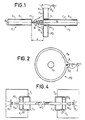
- FIG. 1 schematically represents an optical coupler with adjustable sampling rate according to the invention.
- Two optical fibers F 1 and F 2 are separated by an adjustable distance d.
- the optical fiber F into which has been injected, and guided by its core C 1 , a light wave behaves, by its end face Ft 1 opposite the end face Ft 2 of the fiber optic F 2 , as a divergent light source.
- the emitted beam is included in a cone of axis of symmetry coincident with the common optical axis ⁇ .
- a beam inscribed in a cone B 1 with an angle of the apex a is a useful beam, that is to say captured and guided by the core C 2 of optical fiber F 2 .
- the angle a decreases as the distance d increases.
- an optoelectronic detection element PD comprising, in a central area a circular cavity T, of the same diameter as the outside diameter. of optical fiber F 2 .
- it is a photodiode of annular structure, as shown, from the front, in FIG. 2. It has an active face Fa having an annular shape with an internal diameter equal to the external diameter of the optical fiber F 2 .
- the photodiode can be produced in a conventional manner. Then the central cavity can be carried out simply by selective chemical attack on the central region.
- the photodiode PD has two electrodes E, and E 2 collecting the current i due to the conversion of the light energy received by the active face Fa, electrodes connected to optical links 1.
- the active face Fa receives the light energy of a beam inscribed between the conical envelopes B 1 and B. This energy represents the sample taken, the amplitude or rate of sample increases when the distance d increases.
- the photodiode PD detects, in the absence of losses, an optical power equal to (PO - P c ).
- a conventional method for operating a diameter reduction at the end of an optical fiber is to attack it in a hydrofluoric acid solution.
- a hydrofluoric acid solution For example, a 40% solution is used and the sheath is attacked over about 1 cm in length. The operation can be done at room temperature.
- hydrofluoric acid primarily attacks the core of the fiber.
- the heart To avoid attack of the heart, it must be protected with a wax which is then removed. Since the speed of attack of the sheath is known (approximately 1 micrometer per minute), the duration required can be determined. In addition, a permanent control of the diameter can be carried out. Once the desired diameter is reached, the fiber is rinsed.
- the thickness of the optical cladding can be reduced to a value less than a few micrometers and can be neglected.
- the amplitude of the current i represents the sampling rate.
- FIG. 3 represents a concrete embodiment of an optical coupler with adjustable sampling rate, in section view, incorporating the provisions of the invention.
- the fiber F 1 is held by a cylindrical sleeve 2 and along the axis of symmetry of this sleeve, axis of symmetry coincides with the optical axis A common to the two fibers F, and F 2 to be coupled.
- This cylindrical sleeve 2 slides inside a part 1 comprising a cavity 10 with an interior wall that is also cylindrical.
- the diameters of the two parts are adjusted so that there is a minimum clearance compatible with the precisions necessary for the optical coupling, typically less than 5 micrometers.
- the cylindrical sleeve has an axial cavity 20 and the optical fiber F, is. maintained at its end facing the corresponding end of the fiber F 2 .
- this part 1 has a double cavity 12-11 piercing its wall forming the bottom and extending the main cavity 10.
- the diameter of the cavity 12 is slightly greater than the outside diameter of the disc SP of the photodiode PD, the diameter of the cavity 11 being less than this diameter so that the disc SP of the photodiode PD rests on the periphery on the bottom 120 of the cavity 12.
- Conductors 9 connected to the electrodes E, and E 2 by the connections l make it possible to transmit the signal (i) from the photodiode PD to conventional processing circuits (not shown).
- optical fibers F, and F 2 , the photodiode PD and the electrical conductors 9 can be fixed by a conventional seal.
- the part 1 can be provided with a thread 13 on its outer wall at its open end and a cap 3 also provided with filtering can be screwed onto part 1.
- This cap is pierced with an axial opening 30 letting out the optical fiber F ,.
- This cap blocks the sleeve 2 in the bottom of the cavity 10 by means of an elastic O-ring 8.
- the internal wall of the cavity 10 has a longitudinal groove 4 in which engages a finger 5 integral with the sleeve 2 and serving to guide the latter for translational movements in a direction parallel to the axis ⁇ .
- This finger 5 also serves as a polarizing device to ensure correct relative positions of the sleeve 1 and of the housing 1.
- the precision of machining of the parts must be appropriate to the precision of alignment of the fibers F 1 and F 2 required by the envisaged application, typically less than 5 micrometers.
- the sleeve 2 includes a second longitudinal cavity 21 offset from the axis A but arranged in a direction ⁇ 1 , parallel to this axis.
- the cavity 21 is extended by an additional cavity 22 making it communicate with the outside of the sleeve facing the bottom of the cavity 10 and of diameter smaller than that of the cavity 21.
- the piston is also extended by a finger 72 sliding in the cavity 22 and pressing on the bottom of the cavity 10.
- An additional orifice 14 forming a lumen is drilled in the wall of the part 1 so as to allow free access to this screw.
- the end of the conical screw presses on the end face 70 of the piston 7.
- the latter is planar and forms a bevel inclined relative to the axis ⁇ , at an angle different from ( ⁇ / 2 ) radians.
- the piston 7 also exerts a proportional thrust on the bottom of the cavity 10 and thereby drives the sleeve in translation along the axis ⁇ , l end of the screw sliding on the bevelled face 70 of the piston.
- the sleeve moves away from the bottom of the cavity 10 and crushes, at its other end, the elastic O-ring 8. It is the same for the faces Ft 1 and Ft 2 of the fibers F, and F 2 .
- the allowable amplitude of the crushing must be sufficient to allow variations in the sampling rate within a predetermined range, as previously described.
- the arrangement adopted consisting of the cooperation of a screwing means and the inclined plane of the piston, allows. Therefore good precision in the definition of the distance d separating the two end faces of the optical fibers F 1 and F 2 .
- a displacement amplitude of 460 micrometers is obtained by 11.5 turns of the screw.
- the optical coupler with adjustable sampling rate according to the invention finds an advantageous application in asymmetric type data transmission systems.
- FIG. 4 schematically illustrates a bidirectional simultaneous connection system of this type.
- Two stations T, and T 2 communicate with each other via a fiber optic link FO.
- Each station comprises a light emitter, E, and E 2 respectively , optically coupled via a starter optical fiber, Fa 1 and Fa 2 respectively, to the optical link optical fiber FO.
- couplers with adjustable sampling rate according to the invention, couplers C, and C 2 which constitute detachable connectors.
- the optical fibers FO and Fa 1 play the respective roles of the optical fibers F, and F 2 , the part 1 being able to be fixed to the chassis of station T i .
- each of the optical couplers C, and C 2 are arranged, in accordance with the main characteristic of the invention, a photodiode, PD, and PD 2 respectively. strung on the fiber optic pigtail. Fa 1 and Fa 2 respectively.
- PD 1 and PD 2 photodiodes capture a predetermined fraction of the light generated in the connected station, respectively T 2 and T 1 , according to the adjustment made on the difference (FIG. 1: d) between the terminal faces facing the primed optical fibers, Fa 1 and Fa 2 , and the fiber FO connection optics.
- the light emitters E 1 and E 2 are, for example, light-emitting diodes of the "Ga As” type (gallium arsenide) emitting on a wavelength centered on 0.85 micrometer.
- the optical fiber FO is of a common type with a core diameter of 85 micrometers and a digital opening ON equal to 0.2.
- the attenuation for this type of optical fiber is of the order of 3 db / km at the wavelength 0.85 micrometer.
- the photodiodes can be of the type recalled previously in relation to the description of FIG. 3.
- the optical power P coming from the source E 1 is coupled in the optical fiber FO and, after passing through the two couplers Ci and C 2 , is detected by the photodiode PD 2 according to the preset rate ⁇ 2 of sampling.
- This PD 2 photodiode generates a current which obeys the relationship: in which, k is the sensitivity of the photodiode PD 2 expressed in AW- 1 and A 2 is the transmission factor of the assembly which, for its part, obeys the following relationship: in which A is the transmission factor of the optical fiber FO and any connections arranged along this optical fiber, if it is not made in one piece, and ⁇ 1 and T2 the sampling rates previously defined (relations (1) and (2)) linked to the couplers, Ci and C 2 respectively.
- the sensitivities k 1 and k 2 may be identical or at least little different.
- the removal rate ⁇ 1 was set to 0.1 and the removal rate ⁇ 2 was set to 0.9.
- the values of the optical powers detected by the photodiodes PD 1 and PD 2 make it possible, for example, to produce a video communication link of excellent quality between a central office, station T ,, and a subscriber, station T 2 .
- the return link is used in this application example to convey digital signals of the remote control type or service signals.
- This approach is the one conventionally encountered in a cable distribution system.
- the light emitted by sources E 1 and E 2 is modulated by signals to be transmitted. Conventionally, it suffices to modulate the electrical supply signals of the emitting diodes E 1 and E 2 .
- the frequency spectra associated with the signals transmitted by stations T 1 and T 2 must be distinct.
- the spectrum associated with the video type signals transmitted by the central station T 1 in the example illustrated consists of a wide frequency band, several megahertz or ten megahertz if it is desired to transmit several video channels, while the spectrum associated with the remote control signals transmitted by the subscriber, station 2, is very narrow.
- the output currents of the photodiodes PD 1 and PD 2 are transmitted by the links l 1 to 1 2 to electronic circuits for processing conventional signals (not shown) comprising electric filters.
- a filter tuned on a narrow band, or even on a single frequency is arranged, and in station T 2 , a wide bandwidth filter.
Landscapes
- Physics & Mathematics (AREA)
- General Physics & Mathematics (AREA)
- Optics & Photonics (AREA)
- Electromagnetism (AREA)
- Engineering & Computer Science (AREA)
- Computer Networks & Wireless Communication (AREA)
- Signal Processing (AREA)
- Optical Couplings Of Light Guides (AREA)
Claims (9)
Applications Claiming Priority (2)
| Application Number | Priority Date | Filing Date | Title |
|---|---|---|---|
| FR8402854 | 1984-02-24 | ||
| FR8402854A FR2560395B1 (fr) | 1984-02-24 | 1984-02-24 | Coupleur optoelectronique pour fibres optiques a prelevement reglable et systeme de transmissions bidirectionnelles d'informations mettant en oeuvre un tel coupleur |
Publications (2)
| Publication Number | Publication Date |
|---|---|
| EP0155866A1 EP0155866A1 (de) | 1985-09-25 |
| EP0155866B1 true EP0155866B1 (de) | 1987-12-02 |
Family
ID=9301374
Family Applications (1)
| Application Number | Title | Priority Date | Filing Date |
|---|---|---|---|
| EP85400295A Expired EP0155866B1 (de) | 1984-02-24 | 1985-02-19 | Opto-elektronischer Koppler für optische Faser mit verstellbarer Abzweigung und Zwei-Richtungs-Nachrichten-Übertragungssystem mit Verwendung von solchem Koppler |
Country Status (4)
| Country | Link |
|---|---|
| US (1) | US4668044A (de) |
| EP (1) | EP0155866B1 (de) |
| DE (1) | DE3561119D1 (de) |
| FR (1) | FR2560395B1 (de) |
Families Citing this family (18)
| Publication number | Priority date | Publication date | Assignee | Title |
|---|---|---|---|---|
| US4783137A (en) * | 1983-11-15 | 1988-11-08 | Kosman Karel J | Fiber optic coupling system |
| FR2570836B1 (fr) * | 1984-09-21 | 1987-11-20 | Thomson Csf | Dispositif a ligne a retard optique circulante |
| US4800265A (en) * | 1986-03-21 | 1989-01-24 | Amp Incorporated | Optical fiber continuity testing with pulsating optical test signal |
| US4797556A (en) * | 1986-03-21 | 1989-01-10 | Amp Incorporated | Optical continuity testing apparatus with pulsating transmitter |
| DE3836954A1 (de) * | 1988-10-29 | 1990-05-03 | Philips Patentverwaltung | Verfahren und anordnung zur ermittlung der lage der optischen achse eines lwl |
| US5039191A (en) * | 1990-06-25 | 1991-08-13 | Motorola Inc. | Optical coupling arrangement |
| US5050956A (en) * | 1990-09-20 | 1991-09-24 | Hunter Associates Laboratory Inc. | Optical fiber attenuator and connecting element |
| EP0519210B1 (de) * | 1991-06-10 | 1996-02-28 | International Business Machines Corporation | Einziehbarer faseroptischer Stecker für Computer |
| US5692078A (en) * | 1995-10-19 | 1997-11-25 | Uop | High temperature connector for fused silica capillary body |
| JPH1184182A (ja) * | 1997-09-11 | 1999-03-26 | Sumitomo Wiring Syst Ltd | プラスチック光ファイバと受光素子との接続構造 |
| US6901221B1 (en) | 1999-05-27 | 2005-05-31 | Jds Uniphase Corporation | Method and apparatus for improved optical elements for vertical PCB fiber optic modules |
| US6213651B1 (en) | 1999-05-26 | 2001-04-10 | E20 Communications, Inc. | Method and apparatus for vertical board construction of fiber optic transmitters, receivers and transceivers |
| US6471419B1 (en) | 1999-06-07 | 2002-10-29 | International Business Machines Corporation | Fiber optic assembly |
| DE10106132A1 (de) * | 2001-02-10 | 2002-08-14 | Philips Corp Intellectual Pty | Aufwachschaltung für ein elektrisches Gerät |
| US7040814B2 (en) * | 2001-10-15 | 2006-05-09 | The Furukawa Electric Co., Ltd. | Functional optical module |
| US6954592B2 (en) * | 2002-01-24 | 2005-10-11 | Jds Uniphase Corporation | Systems, methods and apparatus for bi-directional optical transceivers |
| JP4505279B2 (ja) * | 2004-08-02 | 2010-07-21 | 富士フイルム株式会社 | 試料分析用測定装置および測定方法 |
| FR2887082B1 (fr) * | 2005-06-10 | 2009-04-17 | Thales Sa | Laser a semi-conducteur a tres faible bruit |
Family Cites Families (6)
| Publication number | Priority date | Publication date | Assignee | Title |
|---|---|---|---|---|
| US3982123A (en) * | 1974-11-11 | 1976-09-21 | Bell Telephone Laboratories, Incorporated | Optical fiber power taps |
| FR2356171A1 (fr) * | 1976-01-27 | 1978-01-20 | Thomson Csf | Derivation opto-electrique pour liaisons par faisceaux de fibres optiques |
| US4174149A (en) * | 1976-08-19 | 1979-11-13 | The United States Of America As Represented By The Secretary Of The Army | Secure fiber optics communication system |
| FR2503360A1 (fr) * | 1981-04-06 | 1982-10-08 | Thomson Csf | Dispositif emetteur de rayonnement optique a prelevement |
| US4493113A (en) * | 1982-09-10 | 1985-01-08 | At&T Bell Laboratories | Bidirectional fiber optic transmission systems and photodiodes for use in such systems |
| FR2533323A1 (fr) * | 1982-09-17 | 1984-03-23 | Thomson Csf | Dispositif attenuateur optique variable |
-
1984
- 1984-02-24 FR FR8402854A patent/FR2560395B1/fr not_active Expired
-
1985
- 1985-02-19 DE DE8585400295T patent/DE3561119D1/de not_active Expired
- 1985-02-19 EP EP85400295A patent/EP0155866B1/de not_active Expired
- 1985-02-21 US US06/703,886 patent/US4668044A/en not_active Expired - Fee Related
Also Published As
| Publication number | Publication date |
|---|---|
| FR2560395A1 (fr) | 1985-08-30 |
| US4668044A (en) | 1987-05-26 |
| DE3561119D1 (en) | 1988-01-14 |
| FR2560395B1 (fr) | 1986-11-21 |
| EP0155866A1 (de) | 1985-09-25 |
Similar Documents
| Publication | Publication Date | Title |
|---|---|---|
| EP0155866B1 (de) | Opto-elektronischer Koppler für optische Faser mit verstellbarer Abzweigung und Zwei-Richtungs-Nachrichten-Übertragungssystem mit Verwendung von solchem Koppler | |
| EP0121482B1 (de) | Wellenlängenmultiplexer/-demultiplexer und Verfahren zur Herstellung einer solchen Vorrichtung | |
| CN102449519B (zh) | 光接收模块及光接收模块的制造方法 | |
| EP0138698A2 (de) | Optischer Wellenlängen-Multiplexer-Demultiplexer für bidirektionale Verbindung | |
| EP0282766B1 (de) | Aktives optisches Steckergehäuse | |
| FR2581768A1 (fr) | Composant optoelectrique bidirectionnel formant coupleur optique | |
| EP0021897A1 (de) | Optisches Verbindungssystem für die bidirektionale Datenübertragung zwischen einer zentralen Einheit und Unterstationen und dessen Verwendung bei einer elektronisch abtastenden Antenne | |
| CA1250465A (fr) | Commutateur pour circuit a guide de lumiere | |
| FR2533034A1 (fr) | Derivation pour fibre optique | |
| EP1668804B1 (de) | Einkanalige kommunikationseinrichtung für optische faser | |
| EP0147862A1 (de) | Optischer Wellenlängen-Multiplexer-Demultiplexer mit optischen Fasern | |
| EP0148049B1 (de) | Optischer Übertragungskanal mit elektrischen Steckverbindern | |
| EP0346232A2 (de) | Verfahren und System zur Verbindung von Glasfasern ohne Fresnel-Reflexion, veränderlicher optischer Abschwächer und System unter Verwendung desselben zur Messung des Einflusses des Reflexionsgrads auf eine optische Uebertragungsstrecke | |
| EP0083527B1 (de) | Kopplungsvorrichtung für eine Lichtquelle mit divergierender Strahlung und einer optischen Faser | |
| FR2834565A1 (fr) | Dispositif pour faire entrer des signaux optiques dans un guide d'ondes de lumiere et/ou pour les en faire sortir | |
| FR2549243A1 (fr) | Coupleur directif a composants associes pour ondes lumineuses | |
| EP0064919B1 (de) | Vorrichtung zur Ein- und/oder Ausgabe eines optischen Signals | |
| FR2556480A1 (fr) | Coupleur bidirectionnel optique actif | |
| EP0619482A1 (de) | Vorrichtung zur Kontrolle der Kontinuität eines verbindungsabdichteten Klebestrangs | |
| EP0198761B1 (de) | Optischer Koppler, seine Anwendung in einer faseroptischen Drehkupplung und Verfahren zu seiner Herstellung | |
| FR2479618A1 (fr) | Systeme de liaisons bidirectionnelles par cables a fibres optiques et reseau de teledistribution comprenant un tel systeme | |
| FR2756055A1 (fr) | Coupleur optique multimodes et procede pour sa fabrication | |
| FR2490045A1 (fr) | Dispositif d'emission-reception d'energie radiante et systeme de liaisons bidirectionnelles par fibres optiques mettant en oeuvre un tel dispositif | |
| FR2484742A1 (fr) | Systeme de liaisons bidirectionnelles par fibres optiques | |
| FR2503360A1 (fr) | Dispositif emetteur de rayonnement optique a prelevement |
Legal Events
| Date | Code | Title | Description |
|---|---|---|---|
| PUAI | Public reference made under article 153(3) epc to a published international application that has entered the european phase |
Free format text: ORIGINAL CODE: 0009012 |
|
| AK | Designated contracting states |
Designated state(s): DE GB IT NL SE |
|
| 17P | Request for examination filed |
Effective date: 19860224 |
|
| 17Q | First examination report despatched |
Effective date: 19870220 |
|
| GRAA | (expected) grant |
Free format text: ORIGINAL CODE: 0009210 |
|
| AK | Designated contracting states |
Kind code of ref document: B1 Designated state(s): DE GB IT NL SE |
|
| ITF | It: translation for a ep patent filed | ||
| REF | Corresponds to: |
Ref document number: 3561119 Country of ref document: DE Date of ref document: 19880114 |
|
| GBT | Gb: translation of ep patent filed (gb section 77(6)(a)/1977) | ||
| PG25 | Lapsed in a contracting state [announced via postgrant information from national office to epo] |
Ref country code: SE Effective date: 19880220 |
|
| PG25 | Lapsed in a contracting state [announced via postgrant information from national office to epo] |
Ref country code: NL Effective date: 19880901 |
|
| PLBE | No opposition filed within time limit |
Free format text: ORIGINAL CODE: 0009261 |
|
| STAA | Information on the status of an ep patent application or granted ep patent |
Free format text: STATUS: NO OPPOSITION FILED WITHIN TIME LIMIT |
|
| NLV4 | Nl: lapsed or anulled due to non-payment of the annual fee | ||
| PG25 | Lapsed in a contracting state [announced via postgrant information from national office to epo] |
Ref country code: DE Effective date: 19881101 |
|
| 26N | No opposition filed | ||
| PG25 | Lapsed in a contracting state [announced via postgrant information from national office to epo] |
Ref country code: GB Effective date: 19890219 |
|
| GBPC | Gb: european patent ceased through non-payment of renewal fee | ||
| EUG | Se: european patent has lapsed |
Ref document number: 85400295.3 Effective date: 19880927 |