EP0156050A1 - Système de réfrigération et de pompe à chaleur à absorption - Google Patents
Système de réfrigération et de pompe à chaleur à absorption Download PDFInfo
- Publication number
- EP0156050A1 EP0156050A1 EP84301908A EP84301908A EP0156050A1 EP 0156050 A1 EP0156050 A1 EP 0156050A1 EP 84301908 A EP84301908 A EP 84301908A EP 84301908 A EP84301908 A EP 84301908A EP 0156050 A1 EP0156050 A1 EP 0156050A1
- Authority
- EP
- European Patent Office
- Prior art keywords
- subsystem
- heat
- higher temperature
- condenser
- load
- Prior art date
- Legal status (The legal status is an assumption and is not a legal conclusion. Google has not performed a legal analysis and makes no representation as to the accuracy of the status listed.)
- Granted
Links
- 238000010521 absorption reaction Methods 0.000 title claims abstract description 17
- 238000005057 refrigeration Methods 0.000 title claims abstract description 14
- 239000006096 absorbing agent Substances 0.000 claims abstract description 50
- 239000003507 refrigerant Substances 0.000 claims abstract description 43
- 239000000243 solution Substances 0.000 claims description 51
- QGZKDVFQNNGYKY-UHFFFAOYSA-N Ammonia Chemical compound N QGZKDVFQNNGYKY-UHFFFAOYSA-N 0.000 claims description 40
- AMXOYNBUYSYVKV-UHFFFAOYSA-M lithium bromide Chemical compound [Li+].[Br-] AMXOYNBUYSYVKV-UHFFFAOYSA-M 0.000 claims description 37
- XLYOFNOQVPJJNP-UHFFFAOYSA-N water Substances O XLYOFNOQVPJJNP-UHFFFAOYSA-N 0.000 claims description 29
- 229910001868 water Inorganic materials 0.000 claims description 28
- 239000002250 absorbent Substances 0.000 claims description 24
- 238000010438 heat treatment Methods 0.000 claims description 24
- 230000002745 absorbent Effects 0.000 claims description 22
- 238000001816 cooling Methods 0.000 claims description 22
- 229910021529 ammonia Inorganic materials 0.000 claims description 15
- 239000007788 liquid Substances 0.000 claims description 14
- 230000001143 conditioned effect Effects 0.000 claims description 9
- 239000007864 aqueous solution Substances 0.000 claims 4
- VHUUQVKOLVNVRT-UHFFFAOYSA-N Ammonium hydroxide Chemical compound [NH4+].[OH-] VHUUQVKOLVNVRT-UHFFFAOYSA-N 0.000 claims 2
- 235000011114 ammonium hydroxide Nutrition 0.000 claims 2
- 238000005086 pumping Methods 0.000 abstract description 5
- 239000003570 air Substances 0.000 description 41
- 229910000069 nitrogen hydride Inorganic materials 0.000 description 10
- 238000004378 air conditioning Methods 0.000 description 9
- 238000007710 freezing Methods 0.000 description 7
- 230000008014 freezing Effects 0.000 description 7
- 238000010586 diagram Methods 0.000 description 6
- 230000001965 increasing effect Effects 0.000 description 6
- 239000012080 ambient air Substances 0.000 description 5
- 239000012530 fluid Substances 0.000 description 5
- 230000008901 benefit Effects 0.000 description 4
- LYCAIKOWRPUZTN-UHFFFAOYSA-N Ethylene glycol Chemical compound OCCO LYCAIKOWRPUZTN-UHFFFAOYSA-N 0.000 description 3
- 238000002485 combustion reaction Methods 0.000 description 3
- 230000000694 effects Effects 0.000 description 3
- 238000000034 method Methods 0.000 description 3
- 239000002594 sorbent Substances 0.000 description 3
- 230000007797 corrosion Effects 0.000 description 2
- 238000005260 corrosion Methods 0.000 description 2
- 238000010790 dilution Methods 0.000 description 2
- 239000012895 dilution Substances 0.000 description 2
- 239000000284 extract Substances 0.000 description 2
- 239000000446 fuel Substances 0.000 description 2
- 230000006872 improvement Effects 0.000 description 2
- 230000004048 modification Effects 0.000 description 2
- 238000012986 modification Methods 0.000 description 2
- 230000008569 process Effects 0.000 description 2
- 230000001988 toxicity Effects 0.000 description 2
- 231100000419 toxicity Toxicity 0.000 description 2
- 241000928610 Coula Species 0.000 description 1
- WHXSMMKQMYFTQS-UHFFFAOYSA-N Lithium Chemical compound [Li] WHXSMMKQMYFTQS-UHFFFAOYSA-N 0.000 description 1
- 230000003416 augmentation Effects 0.000 description 1
- 230000015556 catabolic process Effects 0.000 description 1
- 230000006835 compression Effects 0.000 description 1
- 238000007906 compression Methods 0.000 description 1
- 239000002826 coolant Substances 0.000 description 1
- 238000006731 degradation reaction Methods 0.000 description 1
- 238000003795 desorption Methods 0.000 description 1
- 230000005611 electricity Effects 0.000 description 1
- 230000002708 enhancing effect Effects 0.000 description 1
- 230000007613 environmental effect Effects 0.000 description 1
- 238000013213 extrapolation Methods 0.000 description 1
- 150000008282 halocarbons Chemical class 0.000 description 1
- 238000009434 installation Methods 0.000 description 1
- 229910052744 lithium Inorganic materials 0.000 description 1
- 239000000463 material Substances 0.000 description 1
- 239000011368 organic material Substances 0.000 description 1
- 230000008707 rearrangement Effects 0.000 description 1
- 238000013112 stability test Methods 0.000 description 1
- 238000010257 thawing Methods 0.000 description 1
Images


Classifications
-
- F—MECHANICAL ENGINEERING; LIGHTING; HEATING; WEAPONS; BLASTING
- F25—REFRIGERATION OR COOLING; COMBINED HEATING AND REFRIGERATION SYSTEMS; HEAT PUMP SYSTEMS; MANUFACTURE OR STORAGE OF ICE; LIQUEFACTION SOLIDIFICATION OF GASES
- F25B—REFRIGERATION MACHINES, PLANTS OR SYSTEMS; COMBINED HEATING AND REFRIGERATION SYSTEMS; HEAT PUMP SYSTEMS
- F25B15/00—Sorption machines, plants or systems, operating continuously, e.g. absorption type
- F25B15/006—Sorption machines, plants or systems, operating continuously, e.g. absorption type with cascade operation
-
- Y—GENERAL TAGGING OF NEW TECHNOLOGICAL DEVELOPMENTS; GENERAL TAGGING OF CROSS-SECTIONAL TECHNOLOGIES SPANNING OVER SEVERAL SECTIONS OF THE IPC; TECHNICAL SUBJECTS COVERED BY FORMER USPC CROSS-REFERENCE ART COLLECTIONS [XRACs] AND DIGESTS
- Y02—TECHNOLOGIES OR APPLICATIONS FOR MITIGATION OR ADAPTATION AGAINST CLIMATE CHANGE
- Y02A—TECHNOLOGIES FOR ADAPTATION TO CLIMATE CHANGE
- Y02A30/00—Adapting or protecting infrastructure or their operation
- Y02A30/27—Relating to heating, ventilation or air conditioning [HVAC] technologies
-
- Y—GENERAL TAGGING OF NEW TECHNOLOGICAL DEVELOPMENTS; GENERAL TAGGING OF CROSS-SECTIONAL TECHNOLOGIES SPANNING OVER SEVERAL SECTIONS OF THE IPC; TECHNICAL SUBJECTS COVERED BY FORMER USPC CROSS-REFERENCE ART COLLECTIONS [XRACs] AND DIGESTS
- Y02—TECHNOLOGIES OR APPLICATIONS FOR MITIGATION OR ADAPTATION AGAINST CLIMATE CHANGE
- Y02B—CLIMATE CHANGE MITIGATION TECHNOLOGIES RELATED TO BUILDINGS, e.g. HOUSING, HOUSE APPLIANCES OR RELATED END-USER APPLICATIONS
- Y02B30/00—Energy efficient heating, ventilation or air conditioning [HVAC]
- Y02B30/62—Absorption based systems
Definitions
- This invention relates to an absorption refrigeration/heat pump system which comprises a higher temperature subsystem and a lower temperature subsystem with various components of the subsystems in heat exchange relationship with one another to provide greater performance than usually obtainable in such systems and/or to permit the use of fluids that have been unsatisfactory in conventional systems. More particularly, it relates to an absorption refrigeration or heat pump system comprising a higher temperature subsystem and a lower temperature subsystem in which the higher temperature condenser is in a heat exchange relationship with the lower temperature desorber and the heating and/or cooling loads are arranged to exchange heat with various combinations of the other components of the system.
- the invention comprises an absorption refrigeration and heat pump system constructed to provide heat to or remove heat from a load when the ambient heat sink or source of heat is above about 45°F comprising at least one first subsystem for operation at higher temperature and at least one second subsystem for operation at lower temperature relative to the first subsystem, each subsystem having components of absorber means, desorber means, condenser means, and evaporator means operatively connected together, with a condenser means of the higher temperature subsystem in heat exchange relationsnip with the desorber means of the lower temperature subsystem; with the evaporator of the higher temperature subsystem and the evaporator of the lower temperature subsystem in series heat exchange relationship with the load in the cooling mode or with the-ambient in the heating mode; and with the absorber of the higher temperature subsystem, the condenser of the lower temperature subsystem, and the absorber of the lower temperature subsystem in series heat exchange relationship with the sink in the cooling mode and the load in the heating mode.
- the evaporator of the higher temperature subsystem When operated with the heat sink or source of heat below 45°F, the evaporator of the higher temperature subsystem is placed in heat exchange relationship with the condenser of the lower temperature subsystem and means is provided to balance the system.
- An additional feature of the invention includes means to pump liquid refrigerant from the condenser of the higher temperature subsystem to the desorber of- the highe-r temperature subsystem to balance the evaporator of the higher temperature subsystem heating requirement with the heating requirement of the condenser of the lower temperature subsystem.
- water is a refrigerant dissolved in a lithium bromide/water solution, often called the "solution pair". Water is absorbed in the lithium bromide solution to varying degrees throughout the sytem and the heat of absorption is added or extracted to produce heating and cooling effects.
- the solution pair enters a generator where it is subjected to heat.
- the applied heat desorbs the refrigerant water in the form of vapor which is conveyed to the condenser.
- external ambient cooling condenses the water vapor to liquid, which is conveyed through an expansion valve, into an evaporator where heat is absorbed.
- the heat absorbed in the evaporator is from the cooling load.
- the low pressure vapor then passes to an absorber where ambient cooling allows the lithium bromide solution to absorb the water vapor.
- the solution pair is then conveyed to a recuperator by a pump.
- the recuperator is a counter flow heat exchanger where heat from the absorbent, lithium bromicie/water solution, flowing from the generator to the absorber, heats.the returning solution pair flowing from the absorber to the generator.
- the cooling applied at the absorber and/or the condenser is the heat delivery to the heating load.
- each part of the aborption system which operates at the same pressure, is termed a chamber.
- the heat pump must act as an air conditioner also to offset the cost of a separate installation of an air conditioner with the furnace.
- PF cooling effect/combustion heat input
- This low performance index causes unreasonable fuel (or energy) costs from excessive fuel (or energy) use.
- This low performance -of the ammonia/water system results from the poor performance characteristics of the ammonia/water solution at the higher temperature ranges if the heat is supplied to the absorption system at higher temperatures.
- the subsystem of this invention employes four chambers. Two chambers are operatively connected in one two-chamber subsystem ana two other chambers are operatively connectea in another subsystem.
- One subsystem employes a higher temperature solution pair having good higher temperature performance properties, preferably lithium bromide/water with water as the refrigerant and lithium bromide as the absorbent.
- the other subsystem employes a different solution pair, preferably ammonia/water, with ammonia as the refrigerant and water as the absorbent.
- the first mentionea subsystem is operatea at higher temperatures and the system configuration allows the pair to be selected to avoid freezing ana crystalization problems.
- the other, second, subsystem employes a lower temperature solution pair having good low temperature perfomance properties and is operated at lower temperatures in the range where an organic should be expected to operate successfully without toxicity corrosion or stability problems and where temperatures below freezing are acceptable.
- the first subsystem and the second subsystem i.e., higher temperature and the lower temperature subsystem respectively, are operatively combined and connected by placing the higher temperature condenser in heat exchange relationship with the lower temperature desorber with other components of the total system also combined in a new and novel way as will be later described.
- U . S. Patent 3,483,710 - Bearint is another example of a prior art version of a four-cnamber system that combines a higher temperature subsystem with a lower temperature subsystem.
- the interrelationships between other components are not the same or arranged to the same advantage as the applicant's invention. This is especially to be noted in connection with the arrangement of various elements with regard to ambient atmosphere conditions and the conditioned atmosphere/or load.
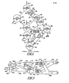
- the hexagonal blocks represent the components of the first subsystem of the invention and the circles represent the components of the second subsystem.
- the first subsystem may be interchangeably termed the "high” subsystem and the second, the "low” subsystem. Components of each may be termed in the same manner, respectively.
- the water in the first (high) subsystem the water is the refrigerant and lithium bromide (LiBr) is the absorbent.
- LiBr lithium bromide
- the higher temperature desorber 30 of the first subsystem is heated by a flame 31 or other means such as electricity.
- the desorber 30 is connected by a suitable conduit 32 to a higher temperature condenser 33.
- the conduit 32 carries superheated refrigerant vapor to the condenser 33. Heat extracted from the condenser causes the refrigerant to conaense to a liquid.
- the condenser 33 is connected to an expansion valve 34 by a conduit 35 which carries the condensed liquid refrigerant.
- Expansion valve 34 is connected to a high evaporator 36 where the low pressure refrigerant vaporizes as it extracts heat from the ambient surroundings.
- the vaporized refrigerant is conveyed by conduit means 37 to a high absorber 38 where it weakens the strong solution supplied to the absorber 38 from conduit 43 through expansion valve 42.
- the desorber 30- is connected to a recuperator 40 by conduit means 41.
- the recuperator 40 is connected to an expansion valve 42 and to the absorber 38 by a conduit means 43.
- the absorber 38 is connected through a pump 44 to the recuperator 40 by a conduit means 45 and the recuperator 40 is connected back to the desorber 30 by a conduit means 46.
- strong absorbent solution is carried from the desorber 30 through the recuperator 40 to the absorber 38 where it absorbs refrigerant and the resulting weak solution is pumped through the recuperator 40 to the desorber 30. Heat is exchanged between the strong absorbent and the weak absorbent solutions in the recuperator 40.
- the two-chamber I,II, higher temperature, first subsystem operates in a typical generally conventional manner.
- the solution pair used in chambers III and IV of the second (lower temperature) subsystem is preferably ammonia and water, with ammonia as the refrigerant and water as the sorbent.
- Conduit 52 may include rectifier sections as typically needed when a volatile sorbent, such as water, is used in a lower temperature solution system, comprising chambers III and IV.
- Condenser 51 is connected through an expansion valve 53 to an evaporator 54 by a conduit means 55.
- Evaporator 54 is connected to an absorber 59 by a conduit means 56 and the exit from the desorber 50 is connected to recuperator 56 by a conduit 57 which continues through an expansion valve 58 to the absorber 59.
- a pump 60 the exit from the absorber 59 is connected through the recuperator 56 to the desorber 50 tnrough conduit means 61.
- ammonia refrigerant vapor is driven from the desorber 50 by heat from the condenser 33 and passes through the conduit means 52 to the condenser 51.
- heat is given up to a cooling medium, and the liquid refrigerant is carried to the expansion valve 53 where it expands into the evaporator and becomes vapor as it receives heat from an external source.
- the refrigerant vapor is carried to the absorber 59 where heat is given up to a sink and refrigerant is absorbed in a strong absorbent solution supplied to the absorber 59 from expansion valve 58.
- the weakened absorbent solution is pumped back to the desorber 50, being warmed by heat exchange in the recuperator 56.
- high evaporator 36 and the low evaporator 54 are connected in series heat exchange relationship with the flow of air from the conditioned living space environment (the load).
- a saturation temperature of 254°F establishes the pressure at 32 psia for operations in chamber I.
- the desorber 30 receives weak absorbent solution (57 % LiBr.) after being heated in the recuperater 40 by the strong absorbent solution leaving the desorber 30 at 60% LiBr and 363°F In the total system in this moae, only the desorber 30 receives heat from the external source 31.
- Saturation conditions at the evaporator 36 establish the pressure of 0.18 Psia and a temperature 50°F.
- the strong absrobent solution enters at a temperature of 121°F and 60% LiBr equilibrium condition. Heat is rejected to the heat sink which in an air conditioning system, may be the outside ambient atmosphere.
- a saturation temperature of 140°F in condenser 51 establishes the pressure at 350 Psia for operations in chamber III with NH 3 /H 2 O as the lower temperature fluid pair.
- the desorber 50 receives weak absorbent solution (42.8% NH 3 ) at a temperature of 237°F and the desorber 50 receives heat from the condenser 33.
- Saturation conditions at the evaporator 54 establishes the pressure at 71 psia at temperature 40°F.
- the absorber 59 receives strong solution at 39.6% NH 3 and a temperature of 131°F, discharges weak solution at approximately 121°F, and gives up heat to the heat sink in heat exchange relationship.
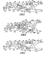
- dampers 122 and 109 With dampers 122 and 109 in the "B" position, return air from the living space supplied by fan 120 is diverted to duct 103, high absorber 38, low absorber 59, and low condenser 51 and then returned to the conditionea air exit duct 129. With dampers 102 and 128 also in the "B” position, outside air passes from inlet 101 through high evaporator 36 ana low evaporator 54 before being drawn to exit duct 110 by fan 111. Dampers 124 and 127 remain in the "A" position and damper 106 remains closed.
- the ambient outside air as a source of heat is caused to flow across the evaporators 36 and 54 which are arranged in series heat exchange relationship with the air passing across the evaporator 36 of the higher temperature subsystem first. Retaining the series nature of the flow of air across the two evaporators allows the outside air to be cooled to temperatures below freezing without freezing the higher temperature evaporator. At the same time, imposing the return air from the living space atmosphere on the high absorber first allows it to be operated away from crystalization region. Subsequent heating of the living space atmosphere by the absorber 59 and the conaenser 51 can be at higher temperatures to minimize the flow of living space air.
- this heat pumping cycle is carried out by imposing rejection heat from the lower temperature subsystem upon the higher temperature evaporator 36.
- the system is configured schematically the same as in Figure 1 except that the evaporator 36 is in heat exchange relationship with the condenser 5l . This is accomplishea by causing the air flow to pass across these components as shown in Figure 6. In order to accomplish this, the ducting configuration is modified as shown in Figure 6.
- Damper valve 106 is located so that it can isolate the condenser inlet 113 and evaporator inlet 125 when closed, but is shown open in Figure 6, allowing recirculation fan 130 to force a separate flow of air from the high evaporator 36 to the low condenser 51. Dampers 124 and 127 and a damper 104 must be in the "B" position and a duct 108 must be added for this recirculation air flow to occur. As in Figure 5, dampers 102, 109, 122, and 128 remain in the "B" position.
- a pump 65 is connected from the condenser 33 to the desorber 30 by a conduit means 66, as shown in Figure 2.
- liquid condensate is pumped from the condenser 33 to the desorber 30 by the pump 65 as necessary to balance the system when the heat rejection from the condenser 51 is made equal to the heat addition to the evaporator 36 .
- Additional heat is supplied by the source 31 to vaporize the additional liquid condensate that is pumped from the condenser 33 to the desorber 30. This supplies extra heat to the condenser 33 which matches the requirements of desorber 50 in this mode of operation.
- the condenser 33 operates at a saturation temperature of 285°F (establishing the chamber I pressure at 53.2 psia) as it gives off heat the desorber 50 operating at a peak solution temperature of 277°F.
- the desorber 30 receives weak absorbent solution at 49.2% LiBr from the recuperator 40 where it is heated by the strong solution leaving the desorber 30 at 375°F and 55.3% LiBr.
- the absorber 38 receives refrigerant vapor at 0.32 psia from evaporator 36 and strong absorbent solution at 125°F and 55.3% LiBr from the recuperator 40. As the solution is cooled by rejecting heat to the air in the living space (the load) the leaving solution is at 106°F and 49.2% LiBr.
- the condenser 51 is assumed to operate at 140°F establishing a pressure of 355° psia in the chamber III.
- the weak absorbent solution enters the desorber 50 at 244°F and 41.2% NH 3 after being recuperatively heated by the strong absorbent solution leaving the desorber 50 at 277°F and 33.3% NH 3 .
- the air flow heat exchange between the condenser 51 and the evaporator 36 establishes the pressure of chamber II at 0.32 psia.
- the subsystems are adjusted so that the heat leaving the condenser 51 is equal to that accepted by the evaporator 36 .
- the evaporator 54 is assumed to operate at -2.5°F establishing 29 psia as the pressure in chamber IV.
- the evaporator 54 extracts heat from the cold outside air and the surface will need to be defrosted periodically.
- the low absorber 59 operates at 29 psia as it rejects heat to air in the heated living space (the load). Strong solution enters the absorber 59 at 103°F and 33.3% NH 3 and leaves at 77°F and 41.2% NH 3 .
- the desorber 50 With the refrigerant flow established to match the heat flow between the condenser 51 and the evaporator 36 , the desorber 50 requires more heat (about one third more in the example) than would normally be rejected by the condenser 33. This short fall of energy is supplied by additional heat input from the source 31. The energy transfer is accomplished by additional flow of liquid refrigerant from a refrigerant well in condenser 33 to the desorDer 30 driven by pump 65. In the desorber 30 it is mixed with the solution supplied by pump 44, accomplishing the desired dilution of the solution flow, and is eventually evaporated by the increased heat flow to supply increased vapor flow to the condenser 33.
- the preferred method of accomplishing this is to include the evaporator 36 and the condenser 51 in the main flow of air to the heated space as shown in Figure 7.
- the evaporator 36 cools the return air and the high absorber 38 heats the return air the same amount so that the mixed temperature entering absorber 59 from duct 112 is the same as the temperature in duct 103.
- the evaporator 36 cools the return air and the high absorber 38 heats the return air the same amount so that the mixed temperature entering absorber 59 from duct 112 is the same as the temperature in duct 103.
- there is a small net gain or loss in return air temperature entering absorber 59 When unbalanced, there is a small net gain or loss in return air temperature entering absorber 59.
- dampers 102, 109, 122, 124, 127, and 128 are in the "B" position and damper valve 106 is open just as in Figure 6. Fan 130 is eliminated and the air flow losses are reduced.
- FIG. 3 an alternative embodiment of the cold ambient heat pump operation is schematically shown in which the heat input to evaporator 36 is virtually eliminated by closing valve 34 and diverting all the refrigerant flow through a dilution reservoir 89, and directing the refrigerant from there through valve 90 to the inlet to solution pump 44.
- This further reduces the LiBr concentration, increasing the vapor release from the solution pump flow without excessively broaaening the concentration differences across desorber 30, ana reducing the temperature in desorber 30.
- some heat flow passes directly from the heat source 31 to the conditioned air by heat transfer from absorber 38.
- Figures 4, 5, 6, and 7 show various direct heat exchange relationships between the components of the absorption system and the air of the conditioned space (the load) and/or the ambient air (the sink or source).
- other means may be used to provide tne heat exchange in the relationships between tnese components ana the load or sink.
- hydronic flow loops i.e., the use of liquid heat exchange materials such as ethylene glycol conveyed in piping between the components and heat exchangers in contact witn the load or sink
- pressure flow relationship of high evaporator ana high absorber shown in Figure 7 coula alternatively be a series flow relationship, either airectly with the conditioned space air flow or with the hydronic flow loops, which delivers heat to the conditioned space.
Landscapes
- Engineering & Computer Science (AREA)
- Physics & Mathematics (AREA)
- Mechanical Engineering (AREA)
- Thermal Sciences (AREA)
- General Engineering & Computer Science (AREA)
- Sorption Type Refrigeration Machines (AREA)
Priority Applications (4)
| Application Number | Priority Date | Filing Date | Title |
|---|---|---|---|
| US06/446,885 US4441332A (en) | 1982-12-06 | 1982-12-06 | Absorption refrigeration and heat pump system |
| EP84301908A EP0156050B1 (fr) | 1982-12-06 | 1984-03-21 | Système de réfrigération et de pompe à chaleur à absorption |
| DE8484301908T DE3478637D1 (en) | 1984-03-21 | 1984-03-21 | Absorption refrigeration and heat pump system |
| AT84301908T ATE43901T1 (de) | 1984-03-21 | 1984-03-21 | Absorptionskaelte- und waermepumpsystem. |
Applications Claiming Priority (2)
| Application Number | Priority Date | Filing Date | Title |
|---|---|---|---|
| US06/446,885 US4441332A (en) | 1982-12-06 | 1982-12-06 | Absorption refrigeration and heat pump system |
| EP84301908A EP0156050B1 (fr) | 1982-12-06 | 1984-03-21 | Système de réfrigération et de pompe à chaleur à absorption |
Publications (2)
| Publication Number | Publication Date |
|---|---|
| EP0156050A1 true EP0156050A1 (fr) | 1985-10-02 |
| EP0156050B1 EP0156050B1 (fr) | 1989-06-07 |
Family
ID=26093389
Family Applications (1)
| Application Number | Title | Priority Date | Filing Date |
|---|---|---|---|
| EP84301908A Expired EP0156050B1 (fr) | 1982-12-06 | 1984-03-21 | Système de réfrigération et de pompe à chaleur à absorption |
Country Status (2)
| Country | Link |
|---|---|
| US (1) | US4441332A (fr) |
| EP (1) | EP0156050B1 (fr) |
Families Citing this family (27)
| Publication number | Priority date | Publication date | Assignee | Title |
|---|---|---|---|---|
| GB8400324D0 (en) * | 1984-01-06 | 1984-02-08 | Ici Plc | Heat pumps |
| IL72882A0 (en) * | 1984-09-06 | 1984-12-31 | Univ Ben Gurion | Absorption system for refrigeration and heat pumping |
| US4646541A (en) * | 1984-11-13 | 1987-03-03 | Columbia Gas System Service Corporation | Absorption refrigeration and heat pump system |
| US4542628A (en) * | 1984-11-13 | 1985-09-24 | The United States Of America As Represented By The United States Department Of Energy | Coupled dual loop absorption heat pump |
| US4593529A (en) * | 1984-12-03 | 1986-06-10 | Birochik Valentine L | Method and apparatus for controlling the temperature and pressure of confined substances |
| DE3503863A1 (de) * | 1985-02-05 | 1986-08-07 | Georg Prof.Dr. 8000 München Alefeld | Anlage mit einem waerme aufnehmenden und waerme abgebenden prozessteil sowie einem eine absorbereinrichtung enthaltenden waermeversorgungsteil |
| FR2590356B1 (fr) * | 1985-11-19 | 1989-06-02 | Jeumont Schneider | Dispositif pour la production en continu de chaud et de froid |
| US4667485A (en) * | 1986-03-14 | 1987-05-26 | Gas Research Institute | Absorption refrigeration and heat pump system |
| US4827728A (en) * | 1986-11-24 | 1989-05-09 | Martin Marietta Energy Systems, Inc. | Seven-effect absorption refrigeration |
| US4732008A (en) * | 1986-11-24 | 1988-03-22 | The United States Of America As Represented By The United States Department Of Energy | Triple effect absorption chiller utilizing two refrigeration circuits |
| EP0326881A1 (fr) * | 1988-02-03 | 1989-08-09 | Aktiebolaget Electrolux | Groupe frigorifique à absorption |
| US4850199A (en) * | 1988-03-21 | 1989-07-25 | Guild Associates, Inc. | Cryo-refrigeration system |
| US4951474A (en) * | 1988-03-21 | 1990-08-28 | Guild Associates, Inc. | Cryo-refrigeration system |
| US4921515A (en) * | 1988-10-20 | 1990-05-01 | Kim Dao | Advanced regenerative absorption refrigeration cycles |
| US5009086A (en) * | 1989-03-30 | 1991-04-23 | Gas Research Institute | Passive refrigeration fluids condition |
| US4926659A (en) * | 1989-03-30 | 1990-05-22 | Gas Research Institute | Double effect air conditioning system |
| IT1242518B (it) * | 1990-08-10 | 1994-05-16 | Roberto Gianfrancesco | Procedimento e macchina di condizionamento dell' aria ad assorbimento |
| US5117648A (en) * | 1990-10-16 | 1992-06-02 | Northeastern University | Refrigeration system with ejector and working fluid storage |
| US5239837A (en) * | 1990-10-16 | 1993-08-31 | Northeastern University | Hydrocarbon fluid, ejector refrigeration system |
| US5287702A (en) * | 1992-05-15 | 1994-02-22 | Preferred Co2 Systems, Inc. | Carbon dioxide storage with thermoelectric cooling for fire suppression systems |
| US5572884A (en) * | 1994-11-04 | 1996-11-12 | The Ohio State University Research Foundation | Heat pump |
| US5761925A (en) * | 1995-12-21 | 1998-06-09 | Ebara Corporation | Absorption heat pump and desiccant assisted air conditioner |
| US5758509A (en) * | 1995-12-21 | 1998-06-02 | Ebara Corporation | Absorption heat pump and desiccant assisted air conditioning apparatus |
| EP2026020B1 (fr) * | 2007-08-09 | 2010-04-14 | Millenium Energy Industries Inc. | Unité de refroidissement d'absorption d'air refroidi à faible température en deux phases |
| DE102009023929A1 (de) * | 2009-06-04 | 2010-12-09 | Stürzebecher, Wolfgang, Dr. | Absorptionskälteaggregat |
| DE102011118873A1 (de) * | 2011-11-18 | 2013-05-23 | Airbus Operations Gmbh | Fahrzeug mit einem Kühlsystem zum Kühlen und Verfahren zum Kühlen in einem Fahrzeug |
| US8720216B1 (en) * | 2013-10-01 | 2014-05-13 | King Fahd University Of Petroleum And Minerals | Hybrid aqua-ammonia and lithium bromide-water absorption chiller |
Citations (9)
| Publication number | Priority date | Publication date | Assignee | Title |
|---|---|---|---|---|
| FR453183A (fr) * | 1911-08-11 | 1913-06-02 | Edmund Altenkirch | Machine à absorption |
| US2182098A (en) * | 1934-09-29 | 1939-12-05 | Mallory & Co Inc P R | Duplex solution thermo-compression process |
| US2212869A (en) * | 1938-09-27 | 1940-08-27 | Herbert W Prafcke | Reversible heating and cooling means and method |
| US3483710A (en) * | 1968-06-13 | 1969-12-16 | Crane Co | Cascade absorption refrigeration system |
| US3854301A (en) * | 1971-06-11 | 1974-12-17 | E Cytryn | Cryogenic absorption cycles |
| US4199959A (en) * | 1977-03-24 | 1980-04-29 | Institute Of Gas Technology | Solid adsorption air conditioning apparatus and method |
| EP0026257A2 (fr) * | 1979-09-28 | 1981-04-08 | Georg Dr. Prof. Alefeld | Installation comportant une pompe à chaleur à absorption |
| EP0052452A2 (fr) * | 1980-11-17 | 1982-05-26 | Kenneth W. Kauffman | Machine thermique à effet variable |
| DE3225613A1 (de) * | 1981-07-10 | 1983-02-10 | Hitachi, Ltd., Tokyo | Absorptionswaermepumpensystem |
Family Cites Families (5)
| Publication number | Priority date | Publication date | Assignee | Title |
|---|---|---|---|---|
| US2350115A (en) * | 1940-05-25 | 1944-05-30 | Katzow Abram | Refrigerating system |
| US3824804A (en) * | 1973-08-22 | 1974-07-23 | C Sandmark | Refrigerating machines |
| US4100755A (en) * | 1976-12-20 | 1978-07-18 | Carrier Corporation | Absorption refrigeration system utilizing solar energy |
| DE2758547A1 (de) * | 1977-12-23 | 1979-06-28 | Borsig Gmbh | Verfahren zur verbesserung der energiebilanz von absorptionskaelteanlagen |
| DE2900388A1 (de) * | 1979-01-04 | 1980-07-10 | Borsig Gmbh | Absorptionskaeltemaschine mit speichereinrichtung fuer den betrieb mit zeitlich unterschiedlichem anfall von heizenergie und kaeltebedarf |
-
1982
- 1982-12-06 US US06/446,885 patent/US4441332A/en not_active Expired - Lifetime
-
1984
- 1984-03-21 EP EP84301908A patent/EP0156050B1/fr not_active Expired
Patent Citations (9)
| Publication number | Priority date | Publication date | Assignee | Title |
|---|---|---|---|---|
| FR453183A (fr) * | 1911-08-11 | 1913-06-02 | Edmund Altenkirch | Machine à absorption |
| US2182098A (en) * | 1934-09-29 | 1939-12-05 | Mallory & Co Inc P R | Duplex solution thermo-compression process |
| US2212869A (en) * | 1938-09-27 | 1940-08-27 | Herbert W Prafcke | Reversible heating and cooling means and method |
| US3483710A (en) * | 1968-06-13 | 1969-12-16 | Crane Co | Cascade absorption refrigeration system |
| US3854301A (en) * | 1971-06-11 | 1974-12-17 | E Cytryn | Cryogenic absorption cycles |
| US4199959A (en) * | 1977-03-24 | 1980-04-29 | Institute Of Gas Technology | Solid adsorption air conditioning apparatus and method |
| EP0026257A2 (fr) * | 1979-09-28 | 1981-04-08 | Georg Dr. Prof. Alefeld | Installation comportant une pompe à chaleur à absorption |
| EP0052452A2 (fr) * | 1980-11-17 | 1982-05-26 | Kenneth W. Kauffman | Machine thermique à effet variable |
| DE3225613A1 (de) * | 1981-07-10 | 1983-02-10 | Hitachi, Ltd., Tokyo | Absorptionswaermepumpensystem |
Also Published As
| Publication number | Publication date |
|---|---|
| US4441332A (en) | 1984-04-10 |
| EP0156050B1 (fr) | 1989-06-07 |
Similar Documents
| Publication | Publication Date | Title |
|---|---|---|
| US4441332A (en) | Absorption refrigeration and heat pump system | |
| US4646537A (en) | Hot water heating and defrost in a heat pump circuit | |
| EP1121565B1 (fr) | Dispositf et méthode de transfert thermique pour pré et/ou sous-refroidir un réfrigérant | |
| EP0702773B1 (fr) | Appareil et procede de transfert de chaleur de type echange de chaleur par generateur-absorbeur et utilisation dudit appareil dans une pompe a chaleur | |
| US4722193A (en) | Absorption refrigeration and heat pump system | |
| US4542628A (en) | Coupled dual loop absorption heat pump | |
| US4924681A (en) | Combined heat pump and domestic water heating circuit | |
| US4667479A (en) | Air and water conditioner for indoor swimming pool | |
| US6718792B1 (en) | Integrated aqua-ammonia chiller/heater | |
| CN108195007A (zh) | 温湿度控制和热量利用的空调系统 | |
| US6631624B1 (en) | Phase-change heat transfer coupling for aqua-ammonia absorption systems | |
| WO2022097134A1 (fr) | Système de chauffage à cascades multiples | |
| EP0725919B1 (fr) | Procede et appareil de transfert de chaleur a echange de chaleur par generateur et absorbeur, et mise en oeuvre dudit procede dans une pompe a chaleur | |
| CN120819898A (zh) | 一种新型双温水路空调系统及其控制方法 | |
| CA1221844A (fr) | Pompe thermique de chauffage et de refrigeration par absorption | |
| CN215809422U (zh) | 空调循环系统以及空调 | |
| GB2305235A (en) | An ejector device for use in a heat pump | |
| KR20230014959A (ko) | 일렉트릭 히트펌프 시스템 | |
| CN113218103A (zh) | 一种风冷热泵系统 | |
| JPH0413620B2 (fr) | ||
| KR102852438B1 (ko) | 성에가 발생되지 않는 히트펌프 냉동싸이클 | |
| CA1281192C (fr) | Systeme de thermopompe a refrigeration par absorption | |
| JPH0835735A (ja) | 吸収式冷凍機 | |
| KR100419479B1 (ko) | 보조냉동기가 부착된 히트펌프시스템 | |
| JPS5886366A (ja) | 冷暖房給湯装置 |
Legal Events
| Date | Code | Title | Description |
|---|---|---|---|
| PUAI | Public reference made under article 153(3) epc to a published international application that has entered the european phase |
Free format text: ORIGINAL CODE: 0009012 |
|
| AK | Designated contracting states |
Designated state(s): AT BE CH DE FR GB IT LI NL SE |
|
| 17P | Request for examination filed |
Effective date: 19860224 |
|
| 17Q | First examination report despatched |
Effective date: 19860703 |
|
| D17Q | First examination report despatched (deleted) | ||
| GRAA | (expected) grant |
Free format text: ORIGINAL CODE: 0009210 |
|
| AK | Designated contracting states |
Kind code of ref document: B1 Designated state(s): AT BE CH DE FR GB IT LI NL SE |
|
| REF | Corresponds to: |
Ref document number: 43901 Country of ref document: AT Date of ref document: 19890615 Kind code of ref document: T |
|
| ITF | It: translation for a ep patent filed | ||
| REF | Corresponds to: |
Ref document number: 3478637 Country of ref document: DE Date of ref document: 19890713 |
|
| ET | Fr: translation filed | ||
| PLBE | No opposition filed within time limit |
Free format text: ORIGINAL CODE: 0009261 |
|
| STAA | Information on the status of an ep patent application or granted ep patent |
Free format text: STATUS: NO OPPOSITION FILED WITHIN TIME LIMIT |
|
| 26N | No opposition filed | ||
| PGFP | Annual fee paid to national office [announced via postgrant information from national office to epo] |
Ref country code: FR Payment date: 19920312 Year of fee payment: 9 |
|
| PGFP | Annual fee paid to national office [announced via postgrant information from national office to epo] |
Ref country code: GB Payment date: 19920316 Year of fee payment: 9 Ref country code: DE Payment date: 19920316 Year of fee payment: 9 Ref country code: CH Payment date: 19920316 Year of fee payment: 9 |
|
| PGFP | Annual fee paid to national office [announced via postgrant information from national office to epo] |
Ref country code: BE Payment date: 19920318 Year of fee payment: 9 |
|
| PGFP | Annual fee paid to national office [announced via postgrant information from national office to epo] |
Ref country code: SE Payment date: 19920323 Year of fee payment: 9 |
|
| PGFP | Annual fee paid to national office [announced via postgrant information from national office to epo] |
Ref country code: AT Payment date: 19920326 Year of fee payment: 9 |
|
| ITTA | It: last paid annual fee | ||
| PGFP | Annual fee paid to national office [announced via postgrant information from national office to epo] |
Ref country code: NL Payment date: 19920331 Year of fee payment: 9 |
|
| PG25 | Lapsed in a contracting state [announced via postgrant information from national office to epo] |
Ref country code: GB Effective date: 19930321 Ref country code: AT Effective date: 19930321 |
|
| PG25 | Lapsed in a contracting state [announced via postgrant information from national office to epo] |
Ref country code: SE Effective date: 19930322 |
|
| PG25 | Lapsed in a contracting state [announced via postgrant information from national office to epo] |
Ref country code: LI Effective date: 19930331 Ref country code: CH Effective date: 19930331 Ref country code: BE Effective date: 19930331 |
|
| BERE | Be: lapsed |
Owner name: GAS RESEARCH INSTITUTE Effective date: 19930331 |
|
| PG25 | Lapsed in a contracting state [announced via postgrant information from national office to epo] |
Ref country code: NL Effective date: 19931001 |
|
| NLV4 | Nl: lapsed or anulled due to non-payment of the annual fee | ||
| GBPC | Gb: european patent ceased through non-payment of renewal fee |
Effective date: 19930321 |
|
| PG25 | Lapsed in a contracting state [announced via postgrant information from national office to epo] |
Ref country code: FR Effective date: 19931130 |
|
| REG | Reference to a national code |
Ref country code: CH Ref legal event code: PL |
|
| PG25 | Lapsed in a contracting state [announced via postgrant information from national office to epo] |
Ref country code: DE Effective date: 19931201 |
|
| REG | Reference to a national code |
Ref country code: FR Ref legal event code: ST |
|
| EUG | Se: european patent has lapsed |
Ref document number: 84301908.4 Effective date: 19931008 |