EP0026257A2 - Installation comportant une pompe à chaleur à absorption - Google Patents
Installation comportant une pompe à chaleur à absorption Download PDFInfo
- Publication number
- EP0026257A2 EP0026257A2 EP80102725A EP80102725A EP0026257A2 EP 0026257 A2 EP0026257 A2 EP 0026257A2 EP 80102725 A EP80102725 A EP 80102725A EP 80102725 A EP80102725 A EP 80102725A EP 0026257 A2 EP0026257 A2 EP 0026257A2
- Authority
- EP
- European Patent Office
- Prior art keywords
- heat
- working medium
- absorption
- expeller
- medium
- Prior art date
- Legal status (The legal status is an assumption and is not a legal conclusion. Google has not performed a legal analysis and makes no representation as to the accuracy of the status listed.)
- Granted
Links
Images

Classifications
-
- F—MECHANICAL ENGINEERING; LIGHTING; HEATING; WEAPONS; BLASTING
- F25—REFRIGERATION OR COOLING; COMBINED HEATING AND REFRIGERATION SYSTEMS; HEAT PUMP SYSTEMS; MANUFACTURE OR STORAGE OF ICE; LIQUEFACTION SOLIDIFICATION OF GASES
- F25B—REFRIGERATION MACHINES, PLANTS OR SYSTEMS; COMBINED HEATING AND REFRIGERATION SYSTEMS; HEAT PUMP SYSTEMS
- F25B30/00—Heat pumps
- F25B30/04—Heat pumps of the sorption type
-
- F—MECHANICAL ENGINEERING; LIGHTING; HEATING; WEAPONS; BLASTING
- F25—REFRIGERATION OR COOLING; COMBINED HEATING AND REFRIGERATION SYSTEMS; HEAT PUMP SYSTEMS; MANUFACTURE OR STORAGE OF ICE; LIQUEFACTION SOLIDIFICATION OF GASES
- F25B—REFRIGERATION MACHINES, PLANTS OR SYSTEMS; COMBINED HEATING AND REFRIGERATION SYSTEMS; HEAT PUMP SYSTEMS
- F25B15/00—Sorption machines, plants or systems, operating continuously, e.g. absorption type
- F25B15/02—Sorption machines, plants or systems, operating continuously, e.g. absorption type without inert gas
- F25B15/06—Sorption machines, plants or systems, operating continuously, e.g. absorption type without inert gas the refrigerant being water vapour evaporated from a salt solution, e.g. lithium bromide
-
- F—MECHANICAL ENGINEERING; LIGHTING; HEATING; WEAPONS; BLASTING
- F25—REFRIGERATION OR COOLING; COMBINED HEATING AND REFRIGERATION SYSTEMS; HEAT PUMP SYSTEMS; MANUFACTURE OR STORAGE OF ICE; LIQUEFACTION SOLIDIFICATION OF GASES
- F25B—REFRIGERATION MACHINES, PLANTS OR SYSTEMS; COMBINED HEATING AND REFRIGERATION SYSTEMS; HEAT PUMP SYSTEMS
- F25B17/00—Sorption machines, plants or systems, operating intermittently, e.g. absorption or adsorption type
- F25B17/08—Sorption machines, plants or systems, operating intermittently, e.g. absorption or adsorption type the absorbent or adsorbent being a solid, e.g. salt
-
- F—MECHANICAL ENGINEERING; LIGHTING; HEATING; WEAPONS; BLASTING
- F25—REFRIGERATION OR COOLING; COMBINED HEATING AND REFRIGERATION SYSTEMS; HEAT PUMP SYSTEMS; MANUFACTURE OR STORAGE OF ICE; LIQUEFACTION SOLIDIFICATION OF GASES
- F25B—REFRIGERATION MACHINES, PLANTS OR SYSTEMS; COMBINED HEATING AND REFRIGERATION SYSTEMS; HEAT PUMP SYSTEMS
- F25B27/00—Machines, plants or systems, using particular sources of energy
- F25B27/002—Machines, plants or systems, using particular sources of energy using solar energy
- F25B27/007—Machines, plants or systems, using particular sources of energy using solar energy in sorption type systems
-
- Y—GENERAL TAGGING OF NEW TECHNOLOGICAL DEVELOPMENTS; GENERAL TAGGING OF CROSS-SECTIONAL TECHNOLOGIES SPANNING OVER SEVERAL SECTIONS OF THE IPC; TECHNICAL SUBJECTS COVERED BY FORMER USPC CROSS-REFERENCE ART COLLECTIONS [XRACs] AND DIGESTS
- Y02—TECHNOLOGIES OR APPLICATIONS FOR MITIGATION OR ADAPTATION AGAINST CLIMATE CHANGE
- Y02A—TECHNOLOGIES FOR ADAPTATION TO CLIMATE CHANGE
- Y02A30/00—Adapting or protecting infrastructure or their operation
- Y02A30/27—Relating to heating, ventilation or air conditioning [HVAC] technologies
-
- Y—GENERAL TAGGING OF NEW TECHNOLOGICAL DEVELOPMENTS; GENERAL TAGGING OF CROSS-SECTIONAL TECHNOLOGIES SPANNING OVER SEVERAL SECTIONS OF THE IPC; TECHNICAL SUBJECTS COVERED BY FORMER USPC CROSS-REFERENCE ART COLLECTIONS [XRACs] AND DIGESTS
- Y02—TECHNOLOGIES OR APPLICATIONS FOR MITIGATION OR ADAPTATION AGAINST CLIMATE CHANGE
- Y02B—CLIMATE CHANGE MITIGATION TECHNOLOGIES RELATED TO BUILDINGS, e.g. HOUSING, HOUSE APPLIANCES OR RELATED END-USER APPLICATIONS
- Y02B30/00—Energy efficient heating, ventilation or air conditioning [HVAC]
- Y02B30/62—Absorption based systems
Definitions
- the present invention relates to a method for operating a system with at least one absorption heat pump, in which a working medium is expelled from an absorbent by supplying heat energy of relatively high temperature, the expelled working medium condenses, the condensed working medium relaxes, the relaxed, condensed working medium with supply evaporated by thermal energy at a relatively low temperature and the evaporated working fluid is finally absorbed again in the absorbent. Furthermore, the invention relates to plants that work according to such a method.
- the present invention is accordingly based on the object of specifying a system for generating heat and / or cold with at least one absorption heat pump, which enables economical operation and the cheapest possible use of the available energy sources.
- the heat or cold energy produced which is available for heating or cooling purposes if required, is not stored, as is known, but operating thermal energy of a relatively high temperature is stored for the absorption heat pump, This means thermal energy that is still increased by the heat pump when heating before being used for heating purposes or that is later used for cooling to cool.
- the thermal energy for an expeller of the heat pump must of course be stored in a temperature range which is sufficient for the operation of the expeller of the absorption heat pump, for which an operating temperature range of the memory from 200 ° C to about 100 ° C. can suffice.
- thermoelectric heat store that is to say a heat store whose maximum operating temperature (temperature of the storage medium at the end of charging) can be up to 800 ° C. and more and generally above 180 ° C., in particular above 200 ° C or 250 ° C will be.
- An important aspect of the present invention is also to provide a sorption storage system that allows the storage of the operating heat for an absorption heat pump at sufficiently high temperatures and can also work as an absorption heat pump, which is operated in a new way with a special absorption medium / working fluid system
- Absorption heat pumps can also be used on their own, that is, without a downstream heat pump and, through them, with operational heat energy (expulsion heat), to a great advantage for heat and / or cold generation.
- heating energy should therefore be understood to mean the relatively high temperature thermal energy used in the expeller to expel the working medium from the absorbent and not the relatively low temperature thermal energy supplied to the evaporator of the heat pump.
- the preferred embodiments of the heat stores described below are harmless, environmentally friendly and work with non-toxic and non-corrosive substances.
- absorption heat pump is also intended to include absorption heat pumps, in which case evaporation and condensation of the working fluid correspond to desorption or resorption.
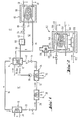
- the system shown in FIG. 1, which can be used for heating and / or cooling, contains an absorption heat pump, designated as a whole by 10, and a heating device, designated as a whole by 12, for an expeller 14 of the heat pump 10.
- the expeller ⁇ 14 contains an absorbent in a known manner, which is capable of absorbing a working fluid which is released from the absorbent again by heating can be driven.
- the expeller 14 has an outlet for gaseous working medium, which is connected via a line 16 to a condenser 18, which works as a heat exchanger and has a heat outlet 20. Useful heat is extracted from a heating system and waste heat is removed from a cooling system.
- Liquefied working fluid is passed from the condenser 18 via a line 22, a throttle element 24 and a line 26 into an evaporator 28, which works as a heat exchanger and has a heat input 30, via which the thermal energy required for the evaporation of the liquefied and relaxed working medium can be supplied.
- the heat input 30 absorbs the heat to be removed.
- the vaporized working fluid is fed via line 32 to an absorber 34, in which the working fluid vapor is absorbed by the absorbent. The heat of absorption released thereby occurs at a useful or waste heat outlet 36 of the absorber.
- the absorbent loaded with working fluid is transported into the expeller 14 via a pump 38.
- the expeller 14 has a heat input part, e.g. in the form of a heating pipe coil 40.
- the heat supplied expels the working medium from the absorption medium again and the absorption medium essentially free of working medium is introduced into the absorber 34 via an absorption medium outlet line 42 and a throttle element 44.
- a heat pump 10 operates continuously and includes other, conventional components which are not shown to simplify the drawing, for example, heat exchanger between rich and poor absorbent solution and between liquid and gaseous working medium.
- heat exchanger between rich and poor absorbent solution and between liquid and gaseous working medium.
- a discontinuously operating heat pump can also be used, as is explained, for example, with reference to FIG. 3 (212).
- the heating device 12 for the absorber heat pump 10 advantageously contains a high-temperature heat accumulator 46.
- a high-temperature heat accumulator is to be understood as a heat accumulator that works with a maximum operating temperature of the storage medium that is above 250 ° C., preferably above 400 ° C. up to Is 800 ° C.
- Such high-temperature heat stores are known and in some cases technically mature.
- Known high-temperature heat stores are e.g. a) ceramic memory, e.g. Memories containing Mg0 ceramics; b) salt stores which store the heat of fusion of salts, e.g. Use LiF from, c) cast iron storage and d) sorption storage. The construction of a suitable sorption storage device will be discussed below with reference to FIG. 3.
- the heat accumulator 46 is heated or “charged” by electrical heating elements.
- the actual storage medium is of course enclosed in a heat-insulating housing 50, which is only shown schematically.
- a heat transfer circuit 52 can be used to transfer the stored heat from the heat store 46 into the expeller 14.
- This contains a coil 54 arranged in the heat accumulator, which is connected via a line 56 is connected to the inlet of the coil 40 forming the heat input part in the expeller 14.
- the outlet of the pipe coil is connected via a line 58 to an intermediate store 60, from which a pipe 62, which contains a control valve 64, leads to the inlet of the pipe coil 54.
- the line 56 carries steam, which condenses in the coil 40 with the emission of heat.
- the condensed water flows via the pipeline 58 into the intermediate storage 60. From there, the water is fed back into the coil 54 in which it evaporates again, as required, via the control valve 64 controlled by a suitable control device.
- the control valve 64 With the help of the control valve 64, the heat or cooling capacity of the absorption heat pump 10 can be continuously and easily controlled, so that good efficiency is ensured.
- a circulation pump 66 is additionally provided in the heat transfer circuit 52. If the delivery rate (throughput) of the circulation pump can be controlled, the control valve 64 can be omitted.
- the heat accumulator which is preferably a high-temperature heat accumulator, such as a ceramic accumulator or cast iron accumulator with maximum operating temperatures of around 800 ° C.
- the heat pump 10 is by Ent Taking heat energy from the heat accumulator 46 operated, the heat removal and thus the heat output and / or cooling output of the heat pump is temporally independent of the charge of the heat accumulator 46 and can be controlled continuously by means of the control valve 64 or the pump 66.
- the expeller 14 can be provided with an auxiliary heating device 15, which enables the heat pump 10 to operate even when the heat store has not yet been charged or the thermal energy stored in it has been used up.
- FIG. 2 shows a modified part of a heating device 112 for a heating system of the type shown in FIG. 1.
- the heating device 112 contains a heat accumulator 146, which is arranged in a combustion chamber 168.
- the combustion chamber 168 is provided with thermal insulation 150 and contains a burner 170 which is supplied with fuel (oil, gas) via a line 172.
- the heat accumulator 146 is preferably a high temperature heat accumulator, e.g. a ceramic or cast iron storage. It can also be heated by electrical heating elements 148.
- the combustion chamber 168 is connected to a chimney 174, which can be closed by a gate valve 176 to prevent heat loss when the burner 170 is not in operation.
- a heat exchanger 178 for utilizing the residual heat of the combustion gases is arranged in the chimney 174 and can be used, for example, to produce hot water.
- heating with solid fuels (coal, wood, combustible waste) or hot exhaust gases may be provided. Otherwise, the heating system can be designed as described with reference to FIG. 1.
- sorption storage that is to say stores which work with desorption and sorption of a working medium from or in a sorbent, for example with the CaO / H 2 O system Sorption stores, which contain zeolite as an absorbent in a very advantageous manner, are preferred.
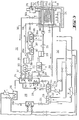
- Fig. 3 shows a further advantageous embodiment of the system according to the invention, which works with a sorption memory.
- Components that correspond to components of the system according to FIGS. 1 and 2 are identified by reference numerals, the first number of which is a 2, while the last two numbers correspond to those of the corresponding components of the system according to FIGS. 1 and 2. 3 therefore only needs to be described insofar as it differs from those according to FIGS. 1 and 2.
- the heater 212 for the expeller 214 of the heat pump 210 is designed in the system according to FIG. 3 as the heat pump upstream of the actual heat pump 210 and contains a sorption heat accumulator 246, which preferably works with zeolite as the absorption medium and water as the working medium.
- a sorption heat accumulator 246, which preferably works with zeolite as the absorption medium and water as the working medium.
- other absorption / working medium systems can also be used, for example zeolite / CH 3 OH zeolite / NH 3 ' CaO 2 / H 2 O or mixtures, which will be discussed further below.
- the heat accumulator 246 has a sealed housing 246a (which can consist of housing modules) in which the absorbent is located (not shown). In the following it is assumed that the absorption medium is zeolite and the working medium is H 2 O.
- the housing is shown schematically as a box, in practice it will generally be made up of several modules in a known manner.
- the housing 246a is connected to a working medium steam outlet line 382, which contains a shut-off valve 382a and leads to a heating coil 340 in the expeller 214 of the absorption heat pump 210.
- the output of the heating coil 340 is connected to a working medium storage vessel 384 which, in the working medium H 2 0 assumed, for example, will contain liquid water.
- the storage vessel 384 has an outlet line 386, which is connected via an optional liquid / gas heat exchanger 387, which is advantageous in the case of high working medium vapor density in the evaporator 394, to a throttle element 388, which consists of a shut-off and control valve and with its low-pressure side an evaporator 394 and the gas side of the heat exchanger 387 is connected to a working medium inlet line 390 of the sorption store 246, which contains a shut-off valve 390a.
- a heat exchanger 392 can advantageously be provided between the outlet side of the heating coil 340 and the inlet of the storage vessel 384, from which useful heat can be removed.
- a coil 254 is also arranged, which serves to dissipate the thermal energy, which is stored in the heat accumulator 246 as specific heat and which is released as sorption heat when the working medium is introduced.
- the pipe coil 254 is connected to a heat transfer circuit 252, for example with water as the heat transfer medium can operate and includes an outlet line connected to the outlet side of the pipe coil-254 which leads to a second heating coil 240 arranged in the expeller 214.
- the outlet side of the heating coil 240 is connected via an outlet line 258, which contains a heat exchanger 304, to the inlet of a heat carrier storage vessel 260, the outlet of which is connected to a control valve 264 (or a controllable pump / corresponding to the pump 66 in FIG. 1) is connected to the inlet end of coil 254.
- the heating coils 340 and 240 therefore both deliver heat energy to the expeller 214 at different times.
- the heat input side of evaporator 394 can be used for cooling purposes. However, if heat is at a higher level, e.g. Exhaust heat or the like is available, the heat input side of the evaporator 394 can be acted upon with a correspondingly high temperature, which has the advantage that the temperature level in the heat accumulator 246 shifts to higher values and correspondingly higher temperatures are available in the heat transfer medium circuit 252.
- a higher level e.g. Exhaust heat or the like
- the heating device 212 can also be operated as a simple (without heat increase) sorption heat store. This has the advantage that a larger part of the useful heat is available as useful heat during the later sorption operation stands. In this case the heating coil 340 is then short-circuited by 341 and the expulsion is carried out in the expeller 246 at such low pressures that the condensation takes place in 392 at ambient temperature. The sorption process proceeds as described and the useful heat generated is removed via the heat transfer circuit 252.
- the system according to FIG. 3 can be modified in that the heating coil 240 is short-circuited by a three-way valve 305 or omitted at all and the heat carrier outlet line 256 is connected directly to the heat exchanger 304. In this case, the heat is then removed as useful heat when the heat accumulator 246 is discharged via the heat exchanger 304, and e.g. used for preparing food, washing, rinsing, heating and the like.
- the heat transfer circuit 252 can be replaced by a blower or the like, which blows air in a controlled manner through corresponding air channels in the storage 246.
- Another variant which also has its special advantages, is to omit the heating coil 340 or to short-circuit it by means of a three-way valve 341.
- the condensation heat that is released when the heat accumulator 246 is loaded and when the storage device 384 is filled is then removed in this case exclusively via the heat exchanger 392 and used as useful heat.
- the heat exchanger 387 and the evaporator 394 can be omitted.
- the working medium circuit also works in a very advantageous manner as a heat pump, and the heat that can be removed by the heat transfer circuit 252 is increased by the amount of heat supplied via the evaporator 394.
- the cooling capacity is additionally increased by the heat absorbed by the evaporator 394.
- the heat accumulator 246 also works as an expeller and as an absorber of a discontinuously operated heat pump, which is to be understood as operation with a time shift or time interval between the expulsion process and the absorption process.
- the construction of the heat pump 10 (Fig. 1) and 210 (Fig. 3) is not limited to a particular type. You can use both continuously working types (as described) as well as types that work discontinuously in the sense defined above for these heat pumps.
- a discontinuously operating absorption heat pump it is known that various components, which have been mentioned individually above, can be functionally combined, for example expeller and absorber and / or evaporator and condenser, which will be explained further below with reference to FIGS. 6 and 7.
- the heating device 212 which supplies the expeller 214 with thermal energy, operates as a discontinuously operated heat pump with respect to the working medium circuit 382-392-384-388-394-390 containing the sorption storage 246. If one uses in the heat accumulator 246, alternatively operated as expeller and absorber, with zeolite as the absorbent, the result is a heat pump system which can also be operated on its own, that is also without a downstream heat pump 210, since it is capable of doing so is to deliver useful heat at temperatures in the order of 100 ° C and above. This is not possible with the known absorption media / working fluid systems.
- the useful heat can be generated at a maximum of 60 ° C and then the pressure of the working fluid when it is driven out is already 30 bar.
- the LiBr / H 2 0 system allows higher useful heat temperatures, but the corrosion problems then become significant and, due to the increasing decomposition of the lithium bromide, a limit is reached even at expeller temperatures of approximately 150 ° C.
- heat pump containing zeolite as the absorbent heat of higher temperature, for example in the temperature range from 150 to 300 ° C. and above, can be used to generate a larger amount of heat at temperatures around 100 ° C.
- the increase in heat is based on the "pumping up" of the inferior low-temperature heat supplied to the evaporator 394, which can be taken, for example, from the ambient air, the groundwater, an "energy roof” or the like.
- system 212 is used without a downstream heat pump 210, the heating coils 240 and 340 are omitted and the useful heat is taken from the condenser 392 and the heat carrier circuit 252. System 212 may also take the place of heat pump 10 in FIG. 1.
- the theoretical performance figure (high-temperature heat used and low-temperature useful heat gained) is 2.0 in each case.
- a power factor of 1.4 can be expected for the heating device and a power factor of 1.5 for the heat pump 210, which results in an overall efficiency of 2.1. If one calculates with the burner 270 with an efficiency of 0.8, which can be achieved with modern oil or gas burners, one obtains a total power factor of 1.7 for the primary energy used.
- the performance figure of the best known absorption heat pump systems is only about 1.2.
- cooling capacity is available on both the evaporator 230 and the evaporator 394.
- the system described above therefore has an efficiency, even when heated with electricity, which is approximately the same as that when a compressor refrigeration machine ( ⁇ ⁇ 2.1) is supplied with electricity from a pump p storage power plant (n ⁇ 0.65).
- a compressor refrigeration machine ⁇ ⁇ 2.1
- n p storage power plant
- EXAMPLE I Absorbent Zeolite; Working medium H 2 0
- the degree of saturation ⁇ of the absorbent is defined as the ratio of the weight of the sorbed H 2 0 to the weight of the zeolite in the desorbed state.
- a absorber operating cycle of the sorption memory 246 :
- This operating mode a) is suitable for a low inlet temperature at the evaporator 394, for example for ice production or cooling.
- Operating modes b) and c) are suitable - for generating a high output temperature in the heat transfer circuit 252.
- the expeller temperature can be reduced at the same expeller pressure and the same condenser temperature.
- x can also have larger values, e.g. 0.5.
- a subdivision of the storage also enables quasi-continuous operation by working the storage parts out of phase, and the efficiency of the system can be improved by internal heat exchange between the storage parts.
- FIG. 4 shows, for example, a sorption memory of the type explained with reference to FIG. 3, which is divided into two halves 246a and 246b, and in a system according to FIG. 3, 6 or 7 and also the system according to FIG. Fig. 1, when the heat pump 10 is a batch heat pump can be used.
- a separate electrical heating device 248a or 248b and / or a separate burner 270a or 270b is provided for each storage half.
- Each storage half also has a working fluid outlet line 382a or 382b, which can optionally be connected to line 382 (FIG. 3) via a three-way valve 402.
- each storage half has a working fluid inlet line 390a or 390b, which can optionally be connected to line 390 via a three-way valve 404.
- Another advantage of subdividing a sorption heat store is that the thermal energy generated in the expeller phase can be "stored” by introducing expelled working fluid into the storage part working in the absorber mode.
- the waste heat obtained from the flue gases can be fed from the heat exchanger 278 (FIG. 4) to the evaporator 394 (FIG. 3). This then increases the temperature level during the absorption phase, since a higher working fluid vapor pressure is set.
- FIG. 5 shows a heat exchanger 504 which can be used with particular advantage instead of the heat exchanger 304 (FIG. 3).
- the temperature of the heat carrier in the heat carrier circuit 252 (FIG. 3) changes relatively strongly during the absorption operating cycle of the absorption heat accumulator 246.
- the heat exchanger 504 is a hot water boiler, to which cold water can be supplied at the bottom via a line 506 and hot water can be taken off via a line 508.
- the line 508 is connected via a three-way valve 510 to a lower and an upper water withdrawal connection 512 or 514 of the hot water boiler.
- the hot water boiler contains, for example, three heating coils 516, 518 and 520.
- the input side of the heating coil 516 is connected to the heat transfer circuit 252 via an input line 307 (see also FIG. 3).
- the input sides of the coil 518 and 520 can be connected to the input line 307 through valves 522 and 524, respectively.
- the output side of the heating coil 516 is connected directly to the input of the heat transfer medium 560, while the output sides of the heating coils 518 and 520 each have a check valve 526 or 528 are connected to the inlet of the heat carrier storage 560.
- the temperature of the heat transfer medium in the heat transfer circuit 252 is still relatively high, the heat transfer medium becomes only through the heating coil 516 passed, the valves 522 and 524 are closed. As the temperature drops, the valve 522 and finally the valve 524 are then opened and the temperature of the heat carrier is thus adapted to the temperature stratification of the water column in the water heater 504.
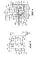
- FIG. 6 shows an embodiment of the invention, which contains a heating device 212 of the type described with reference to FIG. 3, followed by a heat pump 610, which operates discontinuously in the sense defined above.
- the heat pump 610 contains an expeller 614 which is heated by the heating device 212 and which alternately works as expeller and absorber.
- the working medium expelled during the expulsion phase flows through a working medium output line 682 containing a valve 682a to a condenser 618, from which useful or waste heat is extracted via a heat exchanger coil 618a, and is condensed there.
- the condensed, liquid working fluid flows into a storage vessel 600 (which corresponds functionally to the storage vessel 384).
- the liquid working fluid is fed to an evaporator 630, which contains a heat exchanger coil 630a, and which absorbs heat, so that a device connected to the heat exchanger coil 630a can be cooled.
- the evaporated working fluid then flows back from the evaporator 630 via a working fluid inlet line 690, which contains a valve 690a, in particular a non-return valve, to the expeller absorber 614.
- the expeller absorber 614 also contains a device for removing the work fluid from absorption absorbing heat.
- This device 6 is shown as a heat transfer circuit 636, which is a heat exchanger coil 654 which is used to remove the sorption heat and is arranged in the expeller absorber 614, a heat exchanger 604 (for example a space heater or the like) for utilizing or removing the sorption heat removed, a heat carrier supply or expansion tank 660, a control valve 664 and, if necessary, a circulation pump 666.
- the expeller absorber 614 can, however, also be designed such that the sorption heat released during absorption can be removed directly from it, for example by blowing air through a tube system passing through it.
- the expeller absorber 614 operates as an expeller during a first period (expulsion phase).
- the valve 682a is open and the valve 690a is closed.
- the gaseous working medium expelled from the absorbent by the supply of heat from the heating device 212 flows through the line 682 into the condenser 618, where it condenses with the release of useful heat and the condensed working medium is then collected in the storage vessel 600.
- Control valve 624 and valve 690a will generally be closed during this phase.
- the heat transfer circuit 636 is out of operation during this expulsion phase.
- the expeller absorber is switched to absorber operation.
- the valve 682a is closed, the valve 690a is opened and liquid working fluid is regulated by the control valve 624 in accordance with the heating and / or cooling requirement fed into the evaporator 630 from the storage vessel 600.
- the evaporating working fluid absorbs heat so that a device connected to the heat exchanger coil 630a can be cooled.
- absorption heat is released in the expeller absorber 614, which heat is removed via the heat transfer circuit 636 and can be used, for example, for hot water preparation or the surroundings can be dissipated.
- absorbent-working agent system are suitable for FIG. 6:
- the heat transfer medium in the circuit 252 can e.g. Be water (steam) or oil.
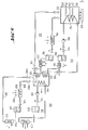
- FIG. 7 shows a schematic illustration of a system according to the invention of the type explained with reference to FIG. 6, but this is done by combining certain structural units and interconnection of the working fluid circuits of the heat pump serving as the heating device and the downstream heat pump is further simplified.
- the working fluid in the two heat pump circuits and the heat transfer medium in the heat transfer circuit must consist of the same substance, for example H 2 0.
- the system according to FIG. 7 contains a sorption memory 246 which alternately works as an expeller and absorber and corresponds to that of the system according to FIG. 3.
- the system also contains an absorber expeller 714, which fulfills the function of the expeller absorber 614 and contains a heating coil 754, which fulfills the functions of the heating and heat exchanger coils 240, 340 and 654 of the system according to FIG. 6.
- An evaporator 794 which fulfills the function of evaporators 394 and 630 (FIG. 6), works together with expeller-absorber heat stores 246 and 714. It is fed by a storage vessel 760, which fulfills the functions of the storage vessels 600 and 384 in FIG. 6.
- a condenser 718 cooperates with the expeller absorber 714 and fulfills the functions of the heat exchanger 604 and the condenser 618.
- the working medium condensed in it flows into a storage vessel 760, which fulfills the functions of the storage vessels 600 and 660 and part of the function of the storage vessel 384.
- the functions of the heat exchanger coils 240, 340 and 654 are performed by a single heat exchanger coil 754.
- a heat exchanger 792 is also provided, which fulfills the functions of the heat exchangers 392 and 304.
- valves 715 and 716 are used to clean the storage containers 760 and 784.
- the removal of working fluid from the storage container 760 for sorption in both 714 and 246 results in a better efficiency in the evaporator 794 because the average temperature level in 760 is lower than in 784.
- Subdivided heat stores 246 can also be used in the systems according to FIGS. 6 and 7, as was explained above with reference to FIG. 4.
- the heat pumps described which work with zeolite as an absorption medium, can be used with great advantage to utilize the waste heat of a gasoline or diesel engine, particularly in quasi-continuous operation with a double accumulator according to FIG. 4, either alone or with a downstream heat pump 210.
- the heat of the exhaust gases is used for expulsion and the cooling water or cooling air heat (cooling fluid heat) is used to heat the evaporator (e.g. 394 in FIG. 3).
- Useful heat is obtained, the temperature of which is above the cooling fluid temperature, so that the entire waste heat of the engine is available at a higher temperature level.
- This heat can be used either directly for heating or via an absorption heat pump (e.g. 210 in Fig. 3) for heating and / or cooling, especially if the engine in turn drives a compressor heat pump.
- the term "storage with a temperature sufficient for expulsion" is intended to mean in general that the stored thermal energy is available at a sufficiently high temperature when it is removed from the heat store.
Landscapes
- Engineering & Computer Science (AREA)
- Physics & Mathematics (AREA)
- Mechanical Engineering (AREA)
- Thermal Sciences (AREA)
- General Engineering & Computer Science (AREA)
- Chemical & Material Sciences (AREA)
- Materials Engineering (AREA)
- Life Sciences & Earth Sciences (AREA)
- Sustainable Development (AREA)
- Sustainable Energy (AREA)
- Sorption Type Refrigeration Machines (AREA)
- Central Heating Systems (AREA)
Priority Applications (1)
| Application Number | Priority Date | Filing Date | Title |
|---|---|---|---|
| AT80102725T ATE28929T1 (de) | 1979-09-28 | 1980-05-16 | Absorptions-waermepumpeanlage. |
Applications Claiming Priority (2)
| Application Number | Priority Date | Filing Date | Title |
|---|---|---|---|
| DE2939423 | 1979-09-17 | ||
| DE19792939423 DE2939423A1 (de) | 1979-09-28 | 1979-09-28 | Verfahren zum betrieb einer eine absorber-waermepumpe enthaltenden heizungsanlage und heizungsanlage zur durchfuehrung dieses verfahrens |
Publications (3)
| Publication Number | Publication Date |
|---|---|
| EP0026257A2 true EP0026257A2 (fr) | 1981-04-08 |
| EP0026257A3 EP0026257A3 (en) | 1982-06-02 |
| EP0026257B1 EP0026257B1 (fr) | 1987-08-12 |
Family
ID=6082167
Family Applications (1)
| Application Number | Title | Priority Date | Filing Date |
|---|---|---|---|
| EP80102725A Expired EP0026257B1 (fr) | 1979-09-28 | 1980-05-16 | Installation comportant une pompe à chaleur à absorption |
Country Status (5)
| Country | Link |
|---|---|
| US (1) | US4408468A (fr) |
| EP (1) | EP0026257B1 (fr) |
| JP (1) | JPS5656567A (fr) |
| AT (1) | ATE28929T1 (fr) |
| DE (2) | DE2939423A1 (fr) |
Cited By (14)
| Publication number | Priority date | Publication date | Assignee | Title |
|---|---|---|---|---|
| EP0042160A3 (en) * | 1980-06-13 | 1982-03-03 | Georg Prof. Dr. Alefeld | Method and means for storing and bringing heat to a higher temperature |
| FR2495497A1 (fr) * | 1980-12-05 | 1982-06-11 | Exxon Research Engineering Co | Procede combine d'absorption et d'adsorption et appareil pour sa mise en oeuvre |
| EP0046112A3 (en) * | 1980-08-11 | 1982-09-01 | Cnrs Centre Nal Rech Scientifique | Method and devices for the revaluation of low-level thermal energy using phenomena of evaporation, and solution of two fluids being in equilibrium of vapour pressure at different temperatures |
| FR2509845A2 (fr) * | 1981-07-16 | 1983-01-21 | Centre Nat Rech Scient | Procede et dispositifs pour la revalorisation d'energie thermique a bas niveau mettant en oeuvre des phenomenes d'evaporation et de melange de deux fluides en equilibre de pression de vapeur sous des temperatures differentes, et application a la valorisation d'une energie thermique noble |
| EP0086383A3 (fr) * | 1982-02-15 | 1983-11-16 | Hieronimi, Ulrich-M. | Appareils à sorption et procédé pour leur mise en oeuvre |
| EP0091095A3 (en) * | 1982-04-05 | 1983-12-07 | Alefeld, Georg, Prof. Dr. | Storage heating plant with sorption reservoir |
| EP0105603A3 (fr) * | 1982-09-03 | 1985-08-07 | Exxon Research And Engineering Company | Pompe à chaleur en tandem |
| EP0156050A1 (fr) * | 1982-12-06 | 1985-10-02 | Gas Research Institute | Système de réfrigération et de pompe à chaleur à absorption |
| DE3532093C1 (de) * | 1985-09-09 | 1987-04-09 | Schiedel Gmbh & Co | Diskontinuierlich arbeitende Sorptions-Speichervorrichtung mit Feststoffabsorber |
| DE4438427A1 (de) * | 1994-10-27 | 1996-05-02 | Zae Bayern Bay Zentrum Fuer An | Mehrstufige Kältemaschine bzw. Wärmepumpe |
| DE102007022950A1 (de) * | 2007-05-16 | 2008-11-20 | Weiss, Dieter | Verfahren zum Transport von Wärmeenergie und Vorrichtungen zur Durchführung eines solchen Verfahrens |
| DE102007039657A1 (de) * | 2007-08-22 | 2009-02-26 | Behr Gmbh & Co. Kg | Vorrichtung zum Heizen und/oder Klimatisieren und Anordnung einer Vorrichtung zum Heizen und/oder Klimatisieren in einem Kraftfahrzeug |
| CN111351107A (zh) * | 2018-12-20 | 2020-06-30 | 大连民族大学 | 混分的太阳能补热溴化锂热泵供暖方法 |
| CN112254377A (zh) * | 2020-10-20 | 2021-01-22 | 山东建筑大学 | 一种R134a-DMF精馏塔吸收式制冷系统及方法 |
Families Citing this family (21)
| Publication number | Priority date | Publication date | Assignee | Title |
|---|---|---|---|---|
| JPS59173700A (ja) * | 1983-03-22 | 1984-10-01 | 三菱重工業株式会社 | ロケツト発射設備の俯仰装置 |
| JPS60173870U (ja) * | 1984-04-23 | 1985-11-18 | 矢崎総業株式会社 | 吸収冷凍機の再生器 |
| JPH0788996B2 (ja) * | 1986-09-24 | 1995-09-27 | 品川燃料株式会社 | 冷却方法 |
| US5598721A (en) * | 1989-03-08 | 1997-02-04 | Rocky Research | Heating and air conditioning systems incorporating solid-vapor sorption reactors capable of high reaction rates |
| US5241831A (en) * | 1989-11-14 | 1993-09-07 | Rocky Research | Continuous constant pressure system for staging solid-vapor compounds |
| US5263330A (en) * | 1989-07-07 | 1993-11-23 | Rocky Research | Discrete constant pressure system for staging solid-vapor compounds |
| US4972679A (en) * | 1990-02-09 | 1990-11-27 | Columbia Gas Service Corporation | Absorption refrigeration and heat pump system with defrost |
| US5360057A (en) * | 1991-09-09 | 1994-11-01 | Rocky Research | Dual-temperature heat pump apparatus and system |
| DE102004053436A1 (de) * | 2004-11-05 | 2006-05-11 | Fraunhofer-Gesellschaft zur Förderung der angewandten Forschung e.V. | PKW-Klimaanlagen mit Adsorptionswärmepumpen |
| FR2886222B1 (fr) * | 2005-05-30 | 2008-12-05 | Giat Ind Sa | Dispositif de gestion de l'energie thermique pour un vehicule |
| FR2904098B1 (fr) * | 2006-07-24 | 2008-09-19 | Cooltech Applic Soc Par Action | Generateur thermique magnetocalorique |
| CN104251571A (zh) * | 2013-06-27 | 2014-12-31 | 朱瑞敏 | 利用地源热泵、太阳能处理工业废热的方法 |
| RU2625073C1 (ru) * | 2016-07-25 | 2017-07-11 | федеральное государственное бюджетное образовательное учреждение высшего образования "Национальный исследовательский университет "МЭИ" (ФГБОУ ВО "НИУ "МЭИ") | Абсорбционная холодильная машина со встроенной теплонасосной установкой |
| CN109990366A (zh) * | 2017-12-29 | 2019-07-09 | 国家电投集团科学技术研究院有限公司 | 储热耦合吸收式热泵供热系统 |
| CN108759159B (zh) * | 2018-05-18 | 2020-09-08 | 北京清天精创节能设备有限公司 | 基于吸收式热泵的高温矿井冷、热源利用系统及运行方式 |
| DE102018010009A1 (de) | 2018-12-28 | 2020-07-02 | Steinbeis Transferzentren GmbH an der Hochschule Karlsruhe | Modulares Sorptionsmodul für eine Adsorptionswärmepumpe |
| IT202100018419A1 (it) * | 2021-07-13 | 2023-01-13 | Mgs S R L | Pompa di calore ad assorbimento perfezionata per uso in impianti di riscaldamento e/o produzione di acqua calda sanitaria con elevate temperature di esercizio |
| DE102022000363A1 (de) | 2022-01-31 | 2023-08-03 | Roland Burk | Mehrkammer-Sorptionsmodul für große Temperaturspreizung und Betriebsverfahren desselben |
| DE102022000362A1 (de) | 2022-01-31 | 2023-08-03 | Roland Burk | Sorptive Wärmetransformationseinrichtung und Verfahren für dessen Betrieb |
| US11879387B2 (en) * | 2022-04-13 | 2024-01-23 | Audubon Engineering Company, L.P. | System and method for diluting vapor and generating electricity |
| CN115183306A (zh) * | 2022-05-31 | 2022-10-14 | 华能营口热电有限责任公司 | 一种脱硫浆液闪蒸与太阳能互补供热的系统及方法 |
Family Cites Families (28)
| Publication number | Priority date | Publication date | Assignee | Title |
|---|---|---|---|---|
| DE596308C (de) * | 1928-08-22 | 1934-05-23 | Wulff Berzelius Normelli | Vorrichtung zur Erzeugung von Waerme durch die Kondensation bzw. Absorption in einer absatzweise wirkenden Absorptionskaeltemaschine |
| US2003310A (en) * | 1932-06-04 | 1935-06-04 | Standard Oil Co | Refrigeration |
| US2182098A (en) * | 1934-09-29 | 1939-12-05 | Mallory & Co Inc P R | Duplex solution thermo-compression process |
| DE818649C (de) * | 1950-01-08 | 1951-10-25 | Heinrich Tritschler K G | Heisswasserspeicher in Verbindung mit einer Absorptionskaelteanlage |
| US3302401A (en) * | 1965-01-26 | 1967-02-07 | United Aircraft Corp | Underwater propulsion system |
| US3483710A (en) * | 1968-06-13 | 1969-12-16 | Crane Co | Cascade absorption refrigeration system |
| DE2112362A1 (de) * | 1971-03-15 | 1972-09-28 | Schantz Hugo Dipl Ing | Hintereinanderschaltung von Waermepumpenkreislaeufen zur Erzeugung verschiedener Temperaturen in den einzelnen Stufen |
| US4034569A (en) * | 1974-11-04 | 1977-07-12 | Tchernev Dimiter I | Sorption system for low-grade (solar) heat utilization |
| US4011731A (en) * | 1974-11-15 | 1977-03-15 | Gershon Meckler | Air conditioning apparatus utilizing solar energy and method |
| US4007776A (en) * | 1974-12-23 | 1977-02-15 | Universal Oil Products Company | Heating and cooling system utilizing solar energy |
| GB1532542A (en) * | 1975-01-14 | 1978-11-15 | Awalt T | Hot or cold storage system |
| US4121566A (en) * | 1975-04-07 | 1978-10-24 | Ljubomir Radenkovic | Sonia system |
| US3973552A (en) * | 1975-06-23 | 1976-08-10 | Rockwell International Corporation | Method of storing and releasing thermal energy |
| DE2622699B2 (en) * | 1976-05-21 | 1978-05-24 | Gebrueder Sulzer Ag, Winterthur (Schweiz) | Absorption heat accumulator element - has absorbent and collector in common tubular gastight vessel with space between |
| US4138855A (en) * | 1976-06-25 | 1979-02-13 | Exxon Research & Engineering Co. | Transferring heat from relatively cold to relatively hot locations |
| JPS533108A (en) * | 1976-06-30 | 1978-01-12 | Nec Corp | Terminating charge system |
| DE2631320C2 (de) * | 1976-07-12 | 1983-05-11 | Alefeld, Georg, Prof.Dr., 8000 München | Verfahren zur Speicherung von Wärme |
| US4070870A (en) * | 1976-10-04 | 1978-01-31 | Borg-Warner Corporation | Heat pump assisted solar powered absorption system |
| GB1572737A (en) * | 1977-01-17 | 1980-08-06 | Exxon France | Heat pump |
| DE2808464A1 (de) * | 1977-03-01 | 1978-09-21 | Pro Elektra Ag Baden | Verfahren und anordnung zur periodischen speicherung und freigabe von waerme |
| US4121432A (en) * | 1977-03-24 | 1978-10-24 | Institute Of Gas Technology | Solid adsorption air conditioning apparatus and method |
| JPS53129333A (en) * | 1977-04-15 | 1978-11-11 | Ai Chiyaanebu Deimitaa | System for absorbing and accumulating low grade heat energy |
| US4134273A (en) * | 1977-04-22 | 1979-01-16 | Brautigam Robert F | Home heating and cooling system |
| DE2737059C3 (de) * | 1977-08-17 | 1981-02-19 | Georg Prof. Dr. 8000 Muenchen Alefeld | Kreisprozeß mit einem Mehrstoffarbeitsmittel |
| US4153104A (en) * | 1977-09-08 | 1979-05-08 | Overland Energy, Inc. | Solar heating and cooling system |
| US4272268A (en) * | 1977-10-17 | 1981-06-09 | Leonard Greiner | Chemical heat pump |
| GB1596786A (en) * | 1978-04-24 | 1981-08-26 | Horstmann Gear Group Ltd | Energy storage devices |
| US4251997A (en) * | 1979-04-02 | 1981-02-24 | Borg-Warner Corporation | Control of absorption systems energized from plural storage tanks maintained at different temperatures |
-
1979
- 1979-09-28 DE DE19792939423 patent/DE2939423A1/de not_active Withdrawn
-
1980
- 1980-05-16 EP EP80102725A patent/EP0026257B1/fr not_active Expired
- 1980-05-16 DE DE8080102725T patent/DE3072006D1/de not_active Expired
- 1980-05-16 AT AT80102725T patent/ATE28929T1/de not_active IP Right Cessation
- 1980-09-17 US US06/188,120 patent/US4408468A/en not_active Expired - Lifetime
- 1980-09-29 JP JP13448880A patent/JPS5656567A/ja active Pending
Cited By (17)
| Publication number | Priority date | Publication date | Assignee | Title |
|---|---|---|---|---|
| EP0042160A3 (en) * | 1980-06-13 | 1982-03-03 | Georg Prof. Dr. Alefeld | Method and means for storing and bringing heat to a higher temperature |
| EP0148756A3 (en) * | 1980-08-11 | 1986-04-23 | Etablissement Public Dit: Centre National De La Recherche Scientifique (Cnrs) | Method and devices for the revaluation of low-level thermal energy using phenomena of evaporation, and solution of two fluids being in equilibrium of vapour pressure at different temperatures |
| EP0046112A3 (en) * | 1980-08-11 | 1982-09-01 | Cnrs Centre Nal Rech Scientifique | Method and devices for the revaluation of low-level thermal energy using phenomena of evaporation, and solution of two fluids being in equilibrium of vapour pressure at different temperatures |
| FR2495497A1 (fr) * | 1980-12-05 | 1982-06-11 | Exxon Research Engineering Co | Procede combine d'absorption et d'adsorption et appareil pour sa mise en oeuvre |
| FR2509845A2 (fr) * | 1981-07-16 | 1983-01-21 | Centre Nat Rech Scient | Procede et dispositifs pour la revalorisation d'energie thermique a bas niveau mettant en oeuvre des phenomenes d'evaporation et de melange de deux fluides en equilibre de pression de vapeur sous des temperatures differentes, et application a la valorisation d'une energie thermique noble |
| EP0086383A3 (fr) * | 1982-02-15 | 1983-11-16 | Hieronimi, Ulrich-M. | Appareils à sorption et procédé pour leur mise en oeuvre |
| EP0091095A3 (en) * | 1982-04-05 | 1983-12-07 | Alefeld, Georg, Prof. Dr. | Storage heating plant with sorption reservoir |
| EP0105603A3 (fr) * | 1982-09-03 | 1985-08-07 | Exxon Research And Engineering Company | Pompe à chaleur en tandem |
| EP0156050A1 (fr) * | 1982-12-06 | 1985-10-02 | Gas Research Institute | Système de réfrigération et de pompe à chaleur à absorption |
| DE3532093C1 (de) * | 1985-09-09 | 1987-04-09 | Schiedel Gmbh & Co | Diskontinuierlich arbeitende Sorptions-Speichervorrichtung mit Feststoffabsorber |
| DE4438427A1 (de) * | 1994-10-27 | 1996-05-02 | Zae Bayern Bay Zentrum Fuer An | Mehrstufige Kältemaschine bzw. Wärmepumpe |
| DE4438427C2 (de) * | 1994-10-27 | 1998-02-12 | Zae Bayern Bayerisches Zentrum Fuer Angewandte Energieforschung Ev | Mehrstufige Kältemaschine bzw. Wärmepumpe |
| DE102007022950A1 (de) * | 2007-05-16 | 2008-11-20 | Weiss, Dieter | Verfahren zum Transport von Wärmeenergie und Vorrichtungen zur Durchführung eines solchen Verfahrens |
| DE102007039657A1 (de) * | 2007-08-22 | 2009-02-26 | Behr Gmbh & Co. Kg | Vorrichtung zum Heizen und/oder Klimatisieren und Anordnung einer Vorrichtung zum Heizen und/oder Klimatisieren in einem Kraftfahrzeug |
| CN111351107A (zh) * | 2018-12-20 | 2020-06-30 | 大连民族大学 | 混分的太阳能补热溴化锂热泵供暖方法 |
| CN112254377A (zh) * | 2020-10-20 | 2021-01-22 | 山东建筑大学 | 一种R134a-DMF精馏塔吸收式制冷系统及方法 |
| CN112254377B (zh) * | 2020-10-20 | 2022-06-17 | 山东建筑大学 | 一种R134a-DMF精馏塔吸收式制冷系统及方法 |
Also Published As
| Publication number | Publication date |
|---|---|
| JPS5656567A (en) | 1981-05-18 |
| EP0026257B1 (fr) | 1987-08-12 |
| ATE28929T1 (de) | 1987-08-15 |
| DE3072006D1 (en) | 1987-09-17 |
| DE2939423A1 (de) | 1981-04-16 |
| EP0026257A3 (en) | 1982-06-02 |
| US4408468A (en) | 1983-10-11 |
Similar Documents
| Publication | Publication Date | Title |
|---|---|---|
| EP0026257B1 (fr) | Installation comportant une pompe à chaleur à absorption | |
| EP0042160B1 (fr) | Procédé et installation pour emmagasiner la chaleur et pour en élever la température | |
| EP0086383A2 (fr) | Appareils à sorption et procédé pour leur mise en oeuvre | |
| EP2076721B1 (fr) | Pompe à chaleur à adsorption dotée d'un accumulateur de chaleur | |
| EP2900943B1 (fr) | Centrale de cogénération et procédé de fonctionnement d'une centrale de cogénération | |
| DE2807075C2 (de) | Verfahren zum Betrieb eines Heizkraftwerkes und geeignetes Heizkraftwerk | |
| CH647590A5 (en) | Process and equipment for producing useful energy from low-grade heat sources | |
| AT394200B (de) | Verfahren zur nutzung und/oder speicherung von energie aus der umwelt | |
| EP0216237A2 (fr) | Accumulateur à sorption à marche discontinue avec un absorbeur contenant un solide | |
| WO2014173572A2 (fr) | Système de centrale électrique à accumulateur thermochimique | |
| DE102012009696A1 (de) | System und Verfahren zur Erzeugung und /oder Speicherung von Wärme und /oder Kälte | |
| DE678942C (de) | Einrichtung zur Waermeumwandlung | |
| EP0091095B1 (fr) | Installation de chauffage par accumulation contenant un réservoir à sorption | |
| EP3497383A1 (fr) | Contenant de transport | |
| DE1020997B (de) | Verfahren zur Wärmeübertragung in Richtung auf höhere Temperatur | |
| DE102020000131B4 (de) | Verfahren zur CO2-Verflüssigung und -Speicherung in einem CO2-Kraftwerk | |
| DE3129957C2 (fr) | ||
| AT511823A4 (de) | Verfahren und einrichtung zur erzeugung von kälte und/oder nutzwärme sowie mechanischer bzw. elektrischer energie mittels eines absorptionskreislaufes | |
| DE102013016461A1 (de) | Verfahren zum Betrieb eines Niedertemperaturkraftwerkes, sowie Niedertemperaturkraftwerk selbst | |
| DE626864C (de) | Ausnutzung und Speicherung der Abwaerme einer kontinuierlichen Absorptionskaeltemaschine | |
| DE3044580C2 (de) | Wärmepumpe und Verfahren zu ihrem Betrieb | |
| DE10240659B4 (de) | Verfahren und Vorrichtung zur solarthermischen Kälteerzeugung | |
| DE2359813A1 (de) | Vorrichtung zur verbesserung des wirkungsgrades von mit dampf betriebenen generatorturbinen | |
| WO2003046449A1 (fr) | Procede et dispositif de production de froid au moyen d'energie solaire | |
| DE102010025504A1 (de) | Verfahren und Anordnung zur Erzeugung von Wärme und Kälte mit einer Kältemaschine |
Legal Events
| Date | Code | Title | Description |
|---|---|---|---|
| PUAI | Public reference made under article 153(3) epc to a published international application that has entered the european phase |
Free format text: ORIGINAL CODE: 0009012 |
|
| AK | Designated contracting states |
Designated state(s): AT BE CH DE FR GB IT NL SE |
|
| PUAL | Search report despatched |
Free format text: ORIGINAL CODE: 0009013 |
|
| AK | Designated contracting states |
Designated state(s): AT BE CH DE FR GB IT NL SE |
|
| 17P | Request for examination filed |
Effective date: 19821130 |
|
| GRAA | (expected) grant |
Free format text: ORIGINAL CODE: 0009210 |
|
| AK | Designated contracting states |
Kind code of ref document: B1 Designated state(s): AT BE CH DE FR GB IT LI NL SE |
|
| PG25 | Lapsed in a contracting state [announced via postgrant information from national office to epo] |
Ref country code: NL Effective date: 19870812 Ref country code: IT Free format text: LAPSE BECAUSE OF FAILURE TO SUBMIT A TRANSLATION OF THE DESCRIPTION OR TO PAY THE FEE WITHIN THE PRESCRIBED TIME-LIMIT;WARNING: LAPSES OF ITALIAN PATENTS WITH EFFECTIVE DATE BEFORE 2007 MAY HAVE OCCURRED AT ANY TIME BEFORE 2007. THE CORRECT EFFECTIVE DATE MAY BE DIFFERENT FROM THE ONE RECORDED. Effective date: 19870812 Ref country code: FR Free format text: THE PATENT HAS BEEN ANNULLED BY A DECISION OF A NATIONAL AUTHORITY Effective date: 19870812 Ref country code: BE Effective date: 19870812 |
|
| REF | Corresponds to: |
Ref document number: 28929 Country of ref document: AT Date of ref document: 19870815 Kind code of ref document: T |
|
| PG25 | Lapsed in a contracting state [announced via postgrant information from national office to epo] |
Ref country code: SE Effective date: 19870831 |
|
| REF | Corresponds to: |
Ref document number: 3072006 Country of ref document: DE Date of ref document: 19870917 |
|
| NLV1 | Nl: lapsed or annulled due to failure to fulfill the requirements of art. 29p and 29m of the patents act | ||
| EN | Fr: translation not filed | ||
| PG25 | Lapsed in a contracting state [announced via postgrant information from national office to epo] |
Ref country code: GB Effective date: 19880516 Ref country code: AT Effective date: 19880516 |
|
| PG25 | Lapsed in a contracting state [announced via postgrant information from national office to epo] |
Ref country code: LI Effective date: 19880531 Ref country code: CH Effective date: 19880531 |
|
| PLBE | No opposition filed within time limit |
Free format text: ORIGINAL CODE: 0009261 |
|
| STAA | Information on the status of an ep patent application or granted ep patent |
Free format text: STATUS: NO OPPOSITION FILED WITHIN TIME LIMIT |
|
| 26N | No opposition filed | ||
| REG | Reference to a national code |
Ref country code: CH Ref legal event code: PL |
|
| GBPC | Gb: european patent ceased through non-payment of renewal fee | ||
| PGFP | Annual fee paid to national office [announced via postgrant information from national office to epo] |
Ref country code: DE Payment date: 19940413 Year of fee payment: 15 |
|
| PG25 | Lapsed in a contracting state [announced via postgrant information from national office to epo] |
Ref country code: DE Effective date: 19960201 |