EP0156068A2 - Dispositif de cintrage - Google Patents
Dispositif de cintrage Download PDFInfo
- Publication number
- EP0156068A2 EP0156068A2 EP84307486A EP84307486A EP0156068A2 EP 0156068 A2 EP0156068 A2 EP 0156068A2 EP 84307486 A EP84307486 A EP 84307486A EP 84307486 A EP84307486 A EP 84307486A EP 0156068 A2 EP0156068 A2 EP 0156068A2
- Authority
- EP
- European Patent Office
- Prior art keywords
- mandrel
- panel
- blocks
- arm
- roller
- Prior art date
- Legal status (The legal status is an assumption and is not a legal conclusion. Google has not performed a legal analysis and makes no representation as to the accuracy of the status listed.)
- Granted
Links
- 238000005452 bending Methods 0.000 title claims abstract description 17
- 229910052751 metal Inorganic materials 0.000 claims abstract description 5
- 239000002184 metal Substances 0.000 claims abstract description 5
- 230000000694 effects Effects 0.000 description 3
- 239000000463 material Substances 0.000 description 3
- 238000010276 construction Methods 0.000 description 2
- 238000003780 insertion Methods 0.000 description 2
- 230000037431 insertion Effects 0.000 description 2
- 229920003023 plastic Polymers 0.000 description 2
- 239000004033 plastic Substances 0.000 description 2
- 239000004411 aluminium Substances 0.000 description 1
- 229910052782 aluminium Inorganic materials 0.000 description 1
- XAGFODPZIPBFFR-UHFFFAOYSA-N aluminium Chemical compound [Al] XAGFODPZIPBFFR-UHFFFAOYSA-N 0.000 description 1
- 239000011324 bead Substances 0.000 description 1
- 230000015572 biosynthetic process Effects 0.000 description 1
- 238000012423 maintenance Methods 0.000 description 1
- 238000004519 manufacturing process Methods 0.000 description 1
- 230000003472 neutralizing effect Effects 0.000 description 1
- 238000007493 shaping process Methods 0.000 description 1
Images



Classifications
-
- B—PERFORMING OPERATIONS; TRANSPORTING
- B21—MECHANICAL METAL-WORKING WITHOUT ESSENTIALLY REMOVING MATERIAL; PUNCHING METAL
- B21D—WORKING OR PROCESSING OF SHEET METAL OR METAL TUBES, RODS OR PROFILES WITHOUT ESSENTIALLY REMOVING MATERIAL; PUNCHING METAL
- B21D7/00—Bending rods, profiles, or tubes
- B21D7/06—Bending rods, profiles, or tubes in press brakes or between rams and anvils or abutments; Pliers with forming dies
- B21D7/063—Pliers with forming dies
Definitions
- the present invention relates to apparatus for bending a light gauge, profiled, metal panel to a curved shape.
- wall and ceiling panelling structure there are several different types of wall and ceiling panelling structure in which there are mounted on support members or stringers spaced parallel panels which are in the form of elongate profiled members of constant cross-section, this cross-section including a web and inturned rims.
- the rims are very often curved and can have a bead at their free ends, the rims thus forming with the web of the panel a generally channel section.
- an apparatus for bending a light gauge, profiled, metal panel to a curved shape comprising a frame,. an anvil mounted on said frame and having a part-annular surface, a pivot bearing on said frame located at the centre of curvature of said part-annular surface, an arm mounted on said bearing for pivotal movement about said centre, a roller carried by said arm at a position spaced from said centre and rotatable about its own axis, so that it can roll in an arc adjacent said annular surface, a mandrel acting as a shape retaining member for the profiled panel, cooperating with said arm for movement therewith at a location between said roller and said surface, said mandrel comprising a plurality of blocks each having its length parallel to the roller axis, the blocks being juxtaposed in side-by-side relation and each shaped to conform to the profile of the panel to be bent, and at least one flexible element for transferring movement of said arm to the mandre
- Provision of the mandrel within the profile of the panel can prevent any uncontrolled buckling of the rims of the panel.
- the apparatus of the present invention is simple in construction and econcomical to manufacture. It can be very efficient in operation and does not require a skilled operator. Because of its simplicity it only-requires a minimum of maintenance and is easily transportable to a building site where the panels are being installed. Once at the building site it can readily be operated quickly to bend the panel to a desired shape.
- the at least one flexible element with respect to said blocks is so arranged that a pulling force on the arm for moving the mandrel. is translated into a pushing force on said mandrel blocks.
- a pulling force on the arm for moving the mandrel. is translated into a pushing force on said mandrel blocks.
- the arm carries a bridge extending over the part-annular surface and the mandrel is connected to the bridge, to be pulled thereby as the arm is moved to bend the panel.
- the bridge may be carried by levers which are pivotally mounted on the arm to facilitate the insertion of the panel before bending.
- a cranked rod is preferably mounted between the levers and carries a guide roll which is adapted to engage the exterior surface of the web of a profile of a panel to be bent.
- the apparatus advantageously includes a clamp positioned to hold the panel against the anvil adjacent the first part of a panel to be bent by the apparatus, and the mandrel is of a length to extend back from the bridge to a position short of the clamp. Because it is short of the clamp it will not be held by the clamp and thereby prevent it moving together with the roller as the arm is moved.
- the mandrel should extend as far back, relative to the movement of the roller, as possible. It should, however, not extend back to within the clamp.
- the connection between the bridge and the mandrel is a lost-motion connection, such that the mandrel does not begin to move until the roller has moved away from the zone of the clamp. This enables the bending operation to start before the mandrel itself starts- to move and thereafter allows the mandrel to extend back by an adequate amount.
- the point of contact of the roller with the panel, or with the mandrel preferably is and remains substantially at the centre of width of a single one of the blocks of the mandrel so that that block will adequately hold the panel, whereas, had the point of con- tack of the roller been over the gap between two blocks, then the blocks would tend to tip and would in fact tend to distort the panel.
- the width of the blocks and the length of the lost motion permitted by the connection is advantageously so chosen that when the roller starts its movement, the point of contact of the roller with the panel or mandrel is substantially at the centre of width of another of the blocks.
- the centre of pressure is at the centre of width of.one of the blocks.
- the roller is preferably mounted between bars pivotally mounted on the arm, to allow a panel to be inserted and removed, and means are provided to lock the bars relative to the arm during pivotal movement of the arm. This facilitates the introduction and removal of a panel but ensures that the roller is correctly positioned during pivoting of the arm.
- the flexible elements of the mandrel may be in the form of wires and an adjustable stop is preferably provided on the or each wire to enable the clearance between adjacent blocks of the mandrel,to be adjusted. Normally the smaller the radius of curvature of the bend in the panel, the larger will be the clearance.
- the blocks are, at least along the circumference of their confronting surfaces, mutually held at a small distance, e.g. by integral or separate distance pieces or parts.
- cavities may be provided at the outer edges of each block at the face adjacent the next block to allow the rims of the panel being bent to buckle slightly thereinto -during the bending of an outside bene.
- the blocks are preferably formed of a low friction plastics material.
- the mandrel blocks may each be formed on one face with a recess, providing a parallel sided groove along one surface of the mandrel in which a smaller cross-section profile can be fitted, so that it can be bent by the apparatus.
- An adjustable fence may be provided against which the end of the panel to be bent can be abutted, thereby determining the position on the panel at which the bend is to be effected.
- an adjustable stop may be provided to limit the pivotal movement of the arm and thus the length of the bend formed.
- the effective length of the arm and the radius of curvature of the curved surface of the anvil can be varied correspondingly, to enable bends of different radii of curvature to be formed.
- the arm may be provided with two spaced bearings to-give two different distances between the bearing and the roller and two cooperating anvils may also be provided, the arrangement being such that bends of two different radii of curvature may be formed on the panels. This is particularly important where one puts an inside bend on one panel and an outside bend on another panel and the two panels are designed to interlock with one another.
- the apparatus illustrated therein comprises a frame 10 in the form of an angled bracket which may be secured to a bench, the frame having mounted thereon an anvil 11 provided with a bearing (not shown) for a shaft 13.
- the shaft 13 has mounted thereon a further bearing 12 adjacent the lower end of an arm 14 which can thus be pivoted about the shaft 13.
- the position illustrated in Figure 1 of the bars 17 is maintained by a spring-loaded locking element 20 which engages in a notch 21 at the top of each bar 17.
- the locking element 20 can be raised to allow disengagement so that the bars 17 can pivot about the axis 16, thus lifting the roller 19 away from the part of the part-annular surface 15.
- pivotally mounted on the arm 14 about axis 22 are a pair of levers 23 having extending therebetween a bridge 24 which overlies the part-annular surface 15.
- the levers"23 also carry therebetween a cranked rod 25 can rockably pivot relative to the lever 23, the cranked portion carrying a guide roll 26.
- a part-annular track 30 Concentric to the part-annular surface 15 is a part-annular track 30 in which is slidable a movable stop 31 which can determine the angular movement through which the arm 14 can be pivoted. A fine adjustment of this movement can be controlled by a threaded abutment bolt 32.
- an adjustable fence 33 Also mounted on the frame is an adjustable fence 33, the position of which to the left or right of that illustrated can be controlled and locked, and the position read off a scale 34 on a support member 35.
- a clamp 36 which includes a block unlike the profile and a movable member.
- the locking element 20 is then disengaged to allow the bars 17 together with the roller 19 to pivot somewhat in a clockwise direction, and then one can insert thrqugh the clamp 36 the panel 100 until it abuts the fence 33.
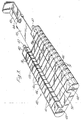
- the bridge 24 has attached thereto, a mandrel indicated by the general reference numeral 40, this consisting of several plastics material blocks 41 arranged . in side-by-side juxtaposed relation.
- a holder 42 is abutted against the end block 41 and has extending therefrom a tongue 43 having a slot 44.
- Engaged in the slot is an element 45 carried by the bridge 24 to allow a lost-motion connection between the mandrel 41 and the bridge 24.
- the several blocks of the bridge extend with their length parallel to the axis of shaft 13 and the blocks have a cross-section conforming to the interior cross-section of a panel to be bent.
- the blocks are held in together by two flexible elements in the form of wires 46 having heads 48 engaged against the righthand block 41, the blocks being held in loose juxtaposed relation by an adjustable stop 47 engaged against the outer surface of the holder 42.
- This arrangement allows the blocks to move slightly relative to one another in a direction generally parallel to the length of the wires 46.
- the mandrel as a whole can conform roughly to the shape of the part-annular surface 15.
- Small cavities 51 are provided at the outer edges of each block at the face of the block abutting the adjacent block to allow the rims of the panel to buckle slightly thereinto to the formation of an outside bend.
- the arm 14 is then pulled in an anti-clockwise direction and it will then start to bend the panel to conform to the shape of the part-annular surface 15.
- the roller will move relative to the mandrel which itself will not move until the element 45 engages the lefthand end of the slot 44.
- the roller will again be above the centre of one of the blocks 41. There will still be three or four blocks to the left of this one block.
- Continued movement to the left will continue to bend the panel and it will also cause the mandrel itself to move with the arm, so that the mandrel is always located within the panel on either side of the point of bending caused by the movement of the roller 19 and the effect of the part-annular surface 15 of the anvil.
- the movement of the mandrel is achieved by the wires -pulling the right-hand- most block 41, which pushes the block to its left. Since the wires are attempting to form a straight line, this, together -with the pushing action, will force the individual blocks radially inwardly, thus assisting in the shaping of the panel. This movement will continue until the arm is prevented from moving further by the stop 31. Thereafter the lock 20 can be released and the arm moved back to the position illustrated in Figure 1.
- the clamp can then be undone and the bent panel removed.
- the thus formed panel has an external curve on it and the provision of the mandrel which is itself capable of taking up the general form of the final curve, will prevent any buckling of the rims of the panel.
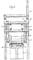
- the panels to be bent is inserted so that its web is below the mandrel 40 and so that it rides over the guide roll 26.
- the operation is substantially the same as before, but in this instance the forming roller 19 runs directly on the blocks of the mandrel.
- the mandrel is, however, still in position within the profile to maintain its shape.
- the purpose of the groove 50 formed by recesses 49 is to enable a smaller profiled panel to be bent, the panel being inserted within this groove and between the bending roller and the base of the groove.
- the anvil is only acting as a guide for the mandrel blocks, the base of the groove then itself acting as an anvil.
- the smaller panel is not subjected to the same stresses and the mandrel will have an embracing effect on it to maintain its rims in their correct position. It is also contemplated that one could fit a-further smaller mandrel within-the smaller profile. Such smaller profiles may be used to connect the larger profiles together.
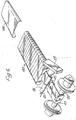
- Figure 5 shows in full lines a panel formed with one internal and one external bend. In phantom are shown further internal and external bends. Any combination of these, one at each side, can be employed, for instance two external or one of each.
Landscapes
- Engineering & Computer Science (AREA)
- Mechanical Engineering (AREA)
- Bending Of Plates, Rods, And Pipes (AREA)
Applications Claiming Priority (2)
| Application Number | Priority Date | Filing Date | Title |
|---|---|---|---|
| GB08405858A GB2155374B (en) | 1984-03-06 | 1984-03-06 | Bending apparatus |
| GB8405858 | 1984-03-06 |
Publications (3)
| Publication Number | Publication Date |
|---|---|
| EP0156068A2 true EP0156068A2 (fr) | 1985-10-02 |
| EP0156068A3 EP0156068A3 (en) | 1986-04-02 |
| EP0156068B1 EP0156068B1 (fr) | 1988-07-13 |
Family
ID=10557663
Family Applications (1)
| Application Number | Title | Priority Date | Filing Date |
|---|---|---|---|
| EP84307486A Expired EP0156068B1 (fr) | 1984-03-06 | 1984-10-31 | Dispositif de cintrage |
Country Status (7)
| Country | Link |
|---|---|
| US (1) | US4608849A (fr) |
| EP (1) | EP0156068B1 (fr) |
| CA (1) | CA1238563A (fr) |
| DE (1) | DE3472636D1 (fr) |
| ES (1) | ES8600089A1 (fr) |
| GB (1) | GB2155374B (fr) |
| ZA (1) | ZA848344B (fr) |
Cited By (3)
| Publication number | Priority date | Publication date | Assignee | Title |
|---|---|---|---|---|
| EP0609767A1 (fr) * | 1993-02-02 | 1994-08-10 | Siemens-Albis Aktiengesellschaft | Procédé et dispositif pour plier des ébauches |
| CN102921778A (zh) * | 2012-10-10 | 2013-02-13 | 河南卫华重型机械股份有限公司 | 多段连续弯弧成型设备 |
| CN108941282A (zh) * | 2018-06-04 | 2018-12-07 | 佛山市信智宇科技服务有限公司 | 一种铝型材弯管装置 |
Families Citing this family (10)
| Publication number | Priority date | Publication date | Assignee | Title |
|---|---|---|---|---|
| DE3526811C1 (de) * | 1985-07-26 | 1987-03-26 | Roland Man Druckmasch | Vorrichtung zum Biegen und Verwinden eines einen Laengsschlitz aufweisenden Rohrs |
| US4719783A (en) * | 1986-05-08 | 1988-01-19 | Joan G. Frost | Portable pipe bending machine |
| US5131254A (en) * | 1991-01-29 | 1992-07-21 | Whitefab, Inc | Apparatus for bending beams |
| US5323631A (en) * | 1993-04-16 | 1994-06-28 | Aluminum Company Of America | Method for forming a hollow workpiece using a snake tool |
| US5819581A (en) * | 1997-03-07 | 1998-10-13 | Winton, Iii; George R. | Mechanism to prevent rotation |
| US7360386B2 (en) * | 2003-10-14 | 2008-04-22 | Century, Inc. | Sweep unit assembly |
| US8084904B2 (en) * | 2004-06-30 | 2011-12-27 | Future Force, Llc | Magnetic propulsion motor |
| US7340933B2 (en) * | 2006-02-16 | 2008-03-11 | Rohr, Inc. | Stretch forming method for a sheet metal skin segment having compound curvatures |
| US8234898B1 (en) * | 2008-12-12 | 2012-08-07 | Wilson Brian S | Bending assembly for extruded stock material |
| CN106541002B (zh) * | 2016-09-26 | 2019-02-05 | 北方华锦化学工业股份有限公司 | 一种u形管煨制装置 |
Family Cites Families (10)
| Publication number | Priority date | Publication date | Assignee | Title |
|---|---|---|---|---|
| US1136252A (en) * | 1914-02-16 | 1915-04-20 | Albert H Meier | Pipe-bending device. |
| US1534314A (en) * | 1923-04-30 | 1925-04-21 | Heintz Mfg Co | Method of bending metal |
| US2044322A (en) * | 1934-06-16 | 1936-06-16 | Murray Corp | Method and means for bending tubing |
| US2108271A (en) * | 1936-07-15 | 1938-02-15 | Howard H Samuel | Channel-iron bending apparatus |
| DE675704C (de) * | 1936-08-16 | 1939-05-15 | Ewald Vollmerhaus | Kette aus gelenkig miteinander verbundenen Druckstuecken an Rohrbiegemaschinen |
| US2255867A (en) * | 1938-07-22 | 1941-09-16 | Douglas & Lomason Co | Bending machine |
| US2342026A (en) * | 1941-06-18 | 1944-02-15 | Budd Edward G Mfg Co | Method of contouring sheet metal |
| US3452571A (en) * | 1967-02-24 | 1969-07-01 | Bend Rite Inc | Tube bending dies |
| US3650136A (en) * | 1969-10-10 | 1972-03-21 | Pines Engineering Co Inc | Tube bending apparatus |
| US4123930A (en) * | 1977-03-29 | 1978-11-07 | Teledyne Industries, Inc. | Mandrel for bending tubes |
-
1984
- 1984-03-06 GB GB08405858A patent/GB2155374B/en not_active Expired
- 1984-10-25 ZA ZA848344A patent/ZA848344B/xx unknown
- 1984-10-29 ES ES537164A patent/ES8600089A1/es not_active Expired
- 1984-10-31 DE DE8484307486T patent/DE3472636D1/de not_active Expired
- 1984-10-31 EP EP84307486A patent/EP0156068B1/fr not_active Expired
- 1984-12-07 US US06/679,508 patent/US4608849A/en not_active Expired - Fee Related
- 1984-12-14 CA CA000470105A patent/CA1238563A/fr not_active Expired
Cited By (4)
| Publication number | Priority date | Publication date | Assignee | Title |
|---|---|---|---|---|
| EP0609767A1 (fr) * | 1993-02-02 | 1994-08-10 | Siemens-Albis Aktiengesellschaft | Procédé et dispositif pour plier des ébauches |
| CN102921778A (zh) * | 2012-10-10 | 2013-02-13 | 河南卫华重型机械股份有限公司 | 多段连续弯弧成型设备 |
| CN102921778B (zh) * | 2012-10-10 | 2015-03-25 | 河南卫华重型机械股份有限公司 | 多段连续弯弧成型设备 |
| CN108941282A (zh) * | 2018-06-04 | 2018-12-07 | 佛山市信智宇科技服务有限公司 | 一种铝型材弯管装置 |
Also Published As
| Publication number | Publication date |
|---|---|
| US4608849A (en) | 1986-09-02 |
| EP0156068A3 (en) | 1986-04-02 |
| ES537164A0 (es) | 1985-09-16 |
| ZA848344B (en) | 1985-06-26 |
| EP0156068B1 (fr) | 1988-07-13 |
| CA1238563A (fr) | 1988-06-28 |
| ES8600089A1 (es) | 1985-09-16 |
| GB8405858D0 (en) | 1984-04-11 |
| GB2155374A (en) | 1985-09-25 |
| GB2155374B (en) | 1987-07-01 |
| DE3472636D1 (en) | 1988-08-18 |
Similar Documents
| Publication | Publication Date | Title |
|---|---|---|
| US4608849A (en) | Bending apparatus | |
| EP0379030B1 (fr) | Ciseaux mobiles montés en amont d'une cintreuse et procédé pour cintrer les bouts arrières de barres | |
| US5461893A (en) | Method and apparatus for bending steel rule | |
| EP0239004B1 (fr) | Laminoir à cylindres de travail déplacable axialement | |
| US4745714A (en) | Articular pole assembly capable of winding | |
| US4355526A (en) | Method and apparatus for uncoiling and straightening material for processing thereof | |
| CA2253087A1 (fr) | Appareil a former des rouleaux transformable | |
| KR20110097946A (ko) | 만곡된 건축 패널, 건축 구조물, 패널 만곡 시스템 및 만곡된 건축 패널을 만들기 위한 방법 | |
| US4993253A (en) | Drawing unit downstream of a bending assembly and method to bend the trailing end of bars | |
| US4898015A (en) | Press brake deflection compensating device | |
| EA015224B1 (ru) | Устройство и способ намотки ребристой ленты на катушку (варианты) | |
| US4240279A (en) | Sheet metal brake | |
| EP0496493B1 (fr) | Agrafeuse médicale | |
| AU2024203646B2 (en) | Bending machine for bending flat material, and method for bending shut a standing fold in a flat material using the bending machine | |
| US4829806A (en) | Variable tube offset bender | |
| EP0198806A2 (fr) | Outil pour mesurer et marquer mécaniquement des longueurs | |
| US4236400A (en) | Vehicle anchoring apparatus | |
| EP0196489B1 (fr) | Dispositif pour emboîter deux tuyaux | |
| US5097692A (en) | Bending apparatus | |
| CH675975A5 (fr) | ||
| JP4830255B2 (ja) | 左右非対称形状の継手を有するハット形鋼矢板の製造方法およびそれに用いる爪曲げ装置 | |
| US4086693A (en) | Manufacture of construction elements | |
| US3961407A (en) | Manufacture of construction elements | |
| EP0191295A2 (fr) | Dispositif pour la fixation de câbles aux câbles porteurs | |
| SE429357B (sv) | Beslagsanordning for fonster, dorrar och liknande |
Legal Events
| Date | Code | Title | Description |
|---|---|---|---|
| PUAI | Public reference made under article 153(3) epc to a published international application that has entered the european phase |
Free format text: ORIGINAL CODE: 0009012 |
|
| AK | Designated contracting states |
Designated state(s): DE FR IT NL |
|
| PUAL | Search report despatched |
Free format text: ORIGINAL CODE: 0009013 |
|
| AK | Designated contracting states |
Kind code of ref document: A3 Designated state(s): DE FR IT NL |
|
| 17P | Request for examination filed |
Effective date: 19860926 |
|
| 17Q | First examination report despatched |
Effective date: 19870415 |
|
| GRAA | (expected) grant |
Free format text: ORIGINAL CODE: 0009210 |
|
| AK | Designated contracting states |
Kind code of ref document: B1 Designated state(s): DE FR IT NL |
|
| REF | Corresponds to: |
Ref document number: 3472636 Country of ref document: DE Date of ref document: 19880818 |
|
| ITF | It: translation for a ep patent filed | ||
| ET | Fr: translation filed | ||
| PLBE | No opposition filed within time limit |
Free format text: ORIGINAL CODE: 0009261 |
|
| STAA | Information on the status of an ep patent application or granted ep patent |
Free format text: STATUS: NO OPPOSITION FILED WITHIN TIME LIMIT |
|
| 26N | No opposition filed | ||
| ITTA | It: last paid annual fee | ||
| PGFP | Annual fee paid to national office [announced via postgrant information from national office to epo] |
Ref country code: DE Payment date: 19931021 Year of fee payment: 10 |
|
| PGFP | Annual fee paid to national office [announced via postgrant information from national office to epo] |
Ref country code: FR Payment date: 19931026 Year of fee payment: 10 |
|
| PGFP | Annual fee paid to national office [announced via postgrant information from national office to epo] |
Ref country code: NL Payment date: 19931031 Year of fee payment: 10 |
|
| PG25 | Lapsed in a contracting state [announced via postgrant information from national office to epo] |
Ref country code: NL Effective date: 19950501 |
|
| NLV4 | Nl: lapsed or anulled due to non-payment of the annual fee | ||
| PG25 | Lapsed in a contracting state [announced via postgrant information from national office to epo] |
Ref country code: FR Effective date: 19950630 |
|
| PG25 | Lapsed in a contracting state [announced via postgrant information from national office to epo] |
Ref country code: DE Effective date: 19950701 |
|
| REG | Reference to a national code |
Ref country code: FR Ref legal event code: ST |