EP0191295A2 - Dispositif pour la fixation de câbles aux câbles porteurs - Google Patents
Dispositif pour la fixation de câbles aux câbles porteurs Download PDFInfo
- Publication number
- EP0191295A2 EP0191295A2 EP86100245A EP86100245A EP0191295A2 EP 0191295 A2 EP0191295 A2 EP 0191295A2 EP 86100245 A EP86100245 A EP 86100245A EP 86100245 A EP86100245 A EP 86100245A EP 0191295 A2 EP0191295 A2 EP 0191295A2
- Authority
- EP
- European Patent Office
- Prior art keywords
- cable
- feed module
- folding
- suspension
- attachment elements
- Prior art date
- Legal status (The legal status is an assumption and is not a legal conclusion. Google has not performed a legal analysis and makes no representation as to the accuracy of the status listed.)
- Withdrawn
Links
- 239000000725 suspension Substances 0.000 claims abstract description 44
- 230000007246 mechanism Effects 0.000 claims abstract description 13
- 238000005452 bending Methods 0.000 claims description 9
- 238000003860 storage Methods 0.000 claims description 7
- 238000010008 shearing Methods 0.000 claims description 4
- 230000001427 coherent effect Effects 0.000 claims description 3
- 230000004913 activation Effects 0.000 claims description 2
- 238000005461 lubrication Methods 0.000 claims description 2
- 230000001360 synchronised effect Effects 0.000 claims description 2
- 230000015572 biosynthetic process Effects 0.000 claims 1
- 238000004049 embossing Methods 0.000 claims 1
- 238000005755 formation reaction Methods 0.000 claims 1
- 230000005540 biological transmission Effects 0.000 abstract description 7
- 238000000034 method Methods 0.000 description 9
- 230000033001 locomotion Effects 0.000 description 3
- 238000003825 pressing Methods 0.000 description 3
- 238000005520 cutting process Methods 0.000 description 2
- 239000000314 lubricant Substances 0.000 description 2
- 239000000463 material Substances 0.000 description 2
- 229910000831 Steel Inorganic materials 0.000 description 1
- 230000004308 accommodation Effects 0.000 description 1
- 230000006978 adaptation Effects 0.000 description 1
- 238000002788 crimping Methods 0.000 description 1
- 238000009434 installation Methods 0.000 description 1
- 210000002445 nipple Anatomy 0.000 description 1
- 238000000926 separation method Methods 0.000 description 1
- 239000010959 steel Substances 0.000 description 1
- 230000008961 swelling Effects 0.000 description 1
Images





Classifications
-
- H—ELECTRICITY
- H02—GENERATION; CONVERSION OR DISTRIBUTION OF ELECTRIC POWER
- H02G—INSTALLATION OF ELECTRIC CABLES OR LINES, OR OF COMBINED OPTICAL AND ELECTRIC CABLES OR LINES
- H02G1/00—Methods or apparatus specially adapted for installing, maintaining, repairing or dismantling electric cables or lines
- H02G1/02—Methods or apparatus specially adapted for installing, maintaining, repairing or dismantling electric cables or lines for overhead lines or cables
-
- Y—GENERAL TAGGING OF NEW TECHNOLOGICAL DEVELOPMENTS; GENERAL TAGGING OF CROSS-SECTIONAL TECHNOLOGIES SPANNING OVER SEVERAL SECTIONS OF THE IPC; TECHNICAL SUBJECTS COVERED BY FORMER USPC CROSS-REFERENCE ART COLLECTIONS [XRACs] AND DIGESTS
- Y10—TECHNICAL SUBJECTS COVERED BY FORMER USPC
- Y10T—TECHNICAL SUBJECTS COVERED BY FORMER US CLASSIFICATION
- Y10T29/00—Metal working
- Y10T29/51—Plural diverse manufacturing apparatus including means for metal shaping or assembling
- Y10T29/5136—Separate tool stations for selective or successive operation on work
- Y10T29/5137—Separate tool stations for selective or successive operation on work including assembling or disassembling station
- Y10T29/5143—Separate tool stations for selective or successive operation on work including assembling or disassembling station and means to machine product
-
- Y—GENERAL TAGGING OF NEW TECHNOLOGICAL DEVELOPMENTS; GENERAL TAGGING OF CROSS-SECTIONAL TECHNOLOGIES SPANNING OVER SEVERAL SECTIONS OF THE IPC; TECHNICAL SUBJECTS COVERED BY FORMER USPC CROSS-REFERENCE ART COLLECTIONS [XRACs] AND DIGESTS
- Y10—TECHNICAL SUBJECTS COVERED BY FORMER USPC
- Y10T—TECHNICAL SUBJECTS COVERED BY FORMER US CLASSIFICATION
- Y10T29/00—Metal working
- Y10T29/51—Plural diverse manufacturing apparatus including means for metal shaping or assembling
- Y10T29/5191—Assembly
Definitions
- the invention relates to a device for attaching cables to suspension ropes, the device which can be moved along the suspension rope carrying a storage container with fastening means which can be separated from one another and which, by means of a folding device made of stamping rollers arranged on both sides of the suspension rope, on the combination to be connected to one another Carrier cable / cable can be stamped, with the fastening means initially being joined together in the form of a band and separable into individual fastening elements by a separating device which is arranged in a feed module for the fastening means.
- a device of the aforementioned type is known from DE-OS 32 28 227.
- a guide channel is formed by guide and pressure rollers, a triggering device for the fastening means being arranged above the carrying cable inserted into the device.
- the fastening means are closed below the suspension cable / cable combination to be connected to one another. So all other devices required for folding are arranged below the suspension cable.
- the folding device is arranged above the supporting rope, that the folding device has a wedge-shaped inlet for the attachment elements, that the feed module in the separating device has a shearing mechanism with several chisels and a counter-roller designed as an abutment, that the feed module is arranged below the cable to be fastened, that the feed module can be unlocked, that a coupled double belt drive for the feed module is arranged in a force-fitting manner on both sides of the suspension cable, that a lifting device for the attachment elements at the exit of the Feed module is arranged, and that a suspension device is arranged.
- An advantage of the device according to the invention is, for example, that it can first be easily attached to the suspension cable and only then is it activated by switching on the drive.
- the drive itself and the workflow controlled by it in the individual mechanisms only starts when the device is pulled along the suspension cable. This is done, for example, by a pull rope from the ground.
- the movement of the device could also be controlled wirelessly if a remotely controllable drive is provided.
- the drive can also be released as required, so that the device can run freely at any time. This measure is particularly important when the device has to be pulled back, for example at a patch or connection point on the suspension cable.
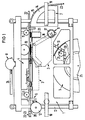
- the storage container 5 for fasteners 19, the feed module 2, the double belt drive 3, the folding device 4, the suspension devices 6 and the release mechanism 8 are arranged functionally in a support frame. Furthermore, the guidance of the support cable 22 and the cable 23 to be attached to it, as well as the partial guidance of the fastening means 19 from the storage container 5 into the feed module 2 can be seen. It can be seen from this that the suspension cable 22, as well as the cable 23, are guided above the feed module 2 and the double belt drive 3, the suspension devices 6 for applying the entire device 1 to the suspension cable 22 being arranged at the beginning and at the end of the device 1 .
- the device 1 is aligned with these suspension aids 6 so that it hangs with its support rollers 11 on the support rope 22 and can thus be moved hanging. Furthermore, in this case, an auxiliary drive roller 10 with a relatively large diameter is arranged in addition to the double belt drive 3, which is mechanically coupled to it via a transmission, so that additional power transmission is achieved.
- the band-shaped connected fastening means 19 fed from the storage container 5 are guided, divided into individual attachment elements 20 and finally passed on to the double belt drive 3. The details are explained in more detail with the aid of detailed figures.
- the feed module 2 can also be activated by a connection mechanism 9 with the aid of a corresponding lever mechanism 16 and possibly with the aid of a controlled motor 17, so that the device as a whole can be pulled along the suspension cable 22 in a "free-running" manner.
- the feeding of the fastening elements 19 which are still wound in a band shape on a drum core are evenly removed from the core 25, which has the profile of the attachment elements 20, via a polygonal disc 21, which rotates in a manner synchronized with the sequence in the feed module 2.
- the longitudinal edges of the disk 21 each correspond to the length of the attachment elements 20 used.
- the cable 23 to be attached to the support cable 22 is fed via the cable feed device 7.
- This cable feed device 7 contains a plurality of cable guides 15, which are arranged on a curved frame 14 and form a groove in which the cable 23 is guided. These cable guides 15 are angular, so that they serve at the same time as dirt wiping for the cable 23.
- the curvature of the frame 14 is selected so that the cable 23 is not bent more than permissible during the feeding, so that there is a perfect protection against kinking or bending. From this figure it can further be seen that after the suspension cable 22 and cable 23 have been merged, the combination suspension cable / cable 22-23 passes through the double belt drive 3, which drives the mechanisms, and the folding device 4 arranged above for the attachment elements 20 and leaves the device at the end with the attachment elements 20, clamped together.
- a guide roller 12 at the end ensures safe locomotion, particularly when the device is returning.
- the unlocking device 8 which is mechanically actuated via a lever 24, the device can be lowered fully functional onto the suspension rope 22 after hanging on the suspension rope 22 with the suspension auxiliary devices 6, while at the same time the frictional contact between the suspension rope 22 and the drive mechanisms is guaranteed.
- a transmission 26 is indicated, which is known per se and via which the synchronization of the two belt drives and the roller 10 takes place.
- This double belt drive 3 essentially consists of two individual belts 27 which are guided on both sides of the support cable 22 in grooves 49 (FIG. 6) by a plurality of guide rollers 28 arranged one behind the other along the support cable 22 when the device 1 is switched on in a force-locking manner.
- the belts 27 are moved as a result of the friction to the support cable 22, the required power transmission being carried out by deflecting the belts via the roller 29 to the feed module and via the rollers 65 to the transmission 26 or the downstream mechanisms .
- FIG. 3 now illustrates the individual attachment elements 20 that are used in the device in one Cross-sectional view in the upper region of the figure and in a plan view of these attachment elements 20, which are combined as a band-shaped fastening means 19, as can be seen from the lower part of the figure.
- the combination of the suspension cable / cable is sunk into the arcuate part of the attachment element 20 with the aid of the device, or the attachment element 20 is raised from below by the feed module 2 to the combination of the suspension cable / cable 22-23.
- the ends 20a, 20b and 20c of the attachment element 20 are already pre-bent in such a way that a simple fold can be produced in the device by simple folding means.
- the individual attachment elements 20 can be supplied in an efficient manner, they are chained together via narrow webs 33 and finally drummed up in a storage container from which they are removed.
- the band-shaped fastening means 19 are separated into individual attachment elements 20 in the feed module 2, as will be explained in more detail in the following figure.
- a hole 32 is provided in each attachment element 20, into which a synchronizing pin 36 is then inserted.
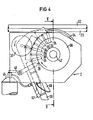
- FIG. 4 shows the feed module 2 in detail.
- This feed module 2 essentially consists of a disk-shaped carrier body 66 on the outer circumference of which the separating tools are arranged in the form of chisels 35 and are evenly distributed.
- these chisels 35 serve to cut off by shearing and not by cutting. This means that the service life of the cutting tools is significantly increased.
- an abutment is required to shear off an object and this abutment is made of hard material by a stepwise rotating disk 37 Material, for example made of steel.
- the distance between the chisel tip and the surface of the abutment is chosen so that it can be sheared properly.
- the attachment elements 20 are pushed in a coherent manner out of the storage container, whereby they are continued in an adapted mold gap within the feed module 2.
- This shaped gap is formed by a shaped piece 67 adapted to the inner shape of the attachment element 20 and an outer shaped sheet 68.
- Synchronizing pins 36 which are each arranged between the chisels 35 on the circumference of the disk-shaped carrier body 66, preferably in divisions of twelve, serve for the right time of the separation.
- the chisels 35 which each have a V-shaped shape on the outside, also take care of the advancement of the attachment elements 20, which reach behind the attachment elements 20 and convey them one step further as the rotation progresses.
- a lubrication device 41 is controlled from the disk 66 via nipples 39, which exerts a brief pressure on a lubricant container 41 after each revolution and thereby deposits a corresponding proportion of lubricant at the required points, for example in the mold gap.
- the separated An is transferred clamp element 20 to the - not shown here - double belt drive, through which it is continued in the folding device.
- the combination of the suspension cable / cable 22-23 to be connected is indicated for orientation.
- the section line for the following FIG. 5 is characterized by the section V-V.
- FIG. 5 illustrates with a section through the drum 66 of the feed module 2 the structure of the lifting device for the attachment elements 20, which is mounted in the drum 66, after they have been separated from the coherent band.
- the attachment elements 20 are guided through the synchronizing pins 36 up to the elevation, these being arranged in each case in a bore in the individual levers 44 of the lifting device.
- the levers 44 are now rotatably mounted parallel to the axis 42 of the drum 66 on the outer circumference with a hinge 4.5 at one end. The other ends of the levers 44 each dip into a deflection groove 43 of a deflection disk 34 arranged parallel to the drum 66.
- This deflection groove 43 is in principle introduced in a circle into the deflection disk 34; however, it has a deflection toward the edge at the deflection point for the attachment elements 20, so that the levers 44 are deflected outward following the movement of their guided ends.
- the result of this is that the attachment element 20 located above the deflected lever 44 is raised to the combination of the carrying cable / cable 22-23 and then at the same time taken over by the belt 27 - not shown here - of the double belt drive 3 and transported further .
- the lever 44 is guided in the retracted state due to the deflection groove 43 and that the synchronizing pin 36 is exposed for the new accommodation of an attachment element 20.
- FIG. 6 shows, with a cross section through the double belt drive 3 in the area of the takeover of a fastening element 20, the guidance of the combination of the carrying rope / cable 22-23, which is pressed in the lower part of the double belt drive 3 against the V-belt 48, which is guided in a system of several identical rollers 47 , so that a clear location is fixed.
- the combination of the suspension cable / cable 22-23 is, however, also guided non-positively between the belts 27 of the double drive 3.
- the drive for the individual mechanisms takes place through the frictional connection.
- the attachment element 20 taken over by the two belts 27 has already been introduced in the correct position for attachment to the combination of the carrying cable / cable 22-23.
- the belts 27 are guided in this area in grooves 49 of the rollers 28, the axes 46 of which are inclined in accordance with the diameter ratio of the suspension cable 22 and the cable 23 in order to achieve an optimal adaptation and thus also power transmission.
- the double belt drive 3 is preferably interchangeable, so that the unit adapted to the diameter ratio can be used in each case.
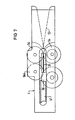
- FIG. 7 shows a top view of the folding device 4, which interacts with the previously described unit of the double belt drive 3.
- the bellows element 20, which is taken over in the double belt drive 3, as can be clearly seen in FIG. 5, is brought together during further transport into the folding device 4 by the wedge-shaped inlet 53 at the upper still open ends 20a and 20b and thus for the pressing process, which is caused by the first pinch roller pair 54 is executed, prepared.
- the attachment element 20 passes into the slot groove 60 of a folding roller 55, the longer, protruding free end of the attachment element 20 being folded back here.
- the fold which has already been formed is bent laterally by a pair of bending rollers 56 and is thus prepared for the final pressing of the fold by a folding roller 57.
- a swelling process is ended and the process begins again for the next one at the selected distance Swell process.
- Figure 8 shows a schematic representation of the pressing of the two ends 20a and 20b by the two pressure rollers 54, which are mounted with their axes 58 perpendicular to the running direction of the suspension cable. For the sake of clarity, all further details are not shown in this and the following illustrations. However, it can be seen here that the longer end 20c of the attachment element 20 still protrudes perpendicularly from the two ends 20a and 20b which have already been compressed.
- FIG. 9 it is indicated how the end 20c of the attachment element 20 which still protrudes vertically in the previous process is folded back over the first end 20a with a folding roller 55 which has a circumferential slot groove 60.
- the attachment element 20 enters the slot groove 60, the free end 20c undergoes a deflection as a result of the rounded flank 61 and finally the crimping onto the ends 20a and 20b which have already been compressed.
- the rounded edge 61 lies thereby on the side of the still protruding end 20c.
- FIG. 10 shows the following process, namely the lateral bending of the already formed fold 62 into an inclined position with the aid of two bending rollers 56 and 56a, the axes 63 of which are arranged perpendicular to the axis 59 of the folding roller 55.
- the edges of the bending rollers 56 and 56a are beveled in opposite directions, so that an obliquely running gap is formed between them, into which the fold 62 runs.
- the two axes 63 are slightly offset from one another, so that the bending roller 56a, the edge of which is wider at the top than at the bottom, first contacts the fold 62 and bends it laterally.
- the fold 62 is further deformed and pressed together in the oblique gap between the two bending rollers 56 and 56a.
- FIG. 11 finally shows the last process in which the fold 62 is pressed by a folding roller 57, the axis 64 of which again runs perpendicular to the axes 63 of the bending rollers 56.
- This folding roller 57 has a pitch circle groove 67 on the circumference. The height of this pitch circle groove 67 is matched to the combination of the carrying cable / cable 22-23 with its attachment element 20 in such a way that the fold 62 is pressed completely down.
- the Anschellvorgang is completed and the combination of carrier cable / cable 22 - 23 leaves in RGBgeschellten state over a final guide roller 12 across the device.
- FIG. 12 finally shows the auxiliary suspension device 6, with the aid of which the device 1 is simply suspended on the suspension cable 22 before the start of the attachment.
- This suspension auxiliary device 6, two of which are arranged in the device 1, consists of a bracket 50 firmly anchored to the device 1, which hooks at both ends 51 and 52 is bent out in a shape.
- the end 51 is preferably designed as a catch hook, while the hook shape of the second end 52 corresponds approximately to the shape, that is to say the diameter, of the support cable 22.
- the position of the end 52 also coincides with the position of the support cable 22 with respect to the further process, except in terms of height.
Landscapes
- Folding Of Thin Sheet-Like Materials, Special Discharging Devices, And Others (AREA)
- Electric Cable Installation (AREA)
- Processing Of Terminals (AREA)
Applications Claiming Priority (2)
| Application Number | Priority Date | Filing Date | Title |
|---|---|---|---|
| DE3504959 | 1985-02-13 | ||
| DE3504959 | 1985-02-13 |
Publications (2)
| Publication Number | Publication Date |
|---|---|
| EP0191295A2 true EP0191295A2 (fr) | 1986-08-20 |
| EP0191295A3 EP0191295A3 (fr) | 1988-11-09 |
Family
ID=6262443
Family Applications (1)
| Application Number | Title | Priority Date | Filing Date |
|---|---|---|---|
| EP86100245A Withdrawn EP0191295A3 (fr) | 1985-02-13 | 1986-01-09 | Dispositif pour la fixation de câbles aux câbles porteurs |
Country Status (2)
| Country | Link |
|---|---|
| US (1) | US4713866A (fr) |
| EP (1) | EP0191295A3 (fr) |
Cited By (2)
| Publication number | Priority date | Publication date | Assignee | Title |
|---|---|---|---|---|
| AT410046B (de) * | 1996-04-15 | 2003-01-27 | Siemens Ag | Vorrichtung und verfahren zum befestigen eines optischen kabels an einem seil einer elektrischen freileitung |
| DE102015219606A1 (de) * | 2015-10-09 | 2017-04-13 | Zumtobel Lighting Gmbh | Verfahren und Vorrichtung zur Befestigung einer länglichen Baueinheit an einer Tragschienenanordnung |
Families Citing this family (3)
| Publication number | Priority date | Publication date | Assignee | Title |
|---|---|---|---|---|
| US6684514B2 (en) | 2001-04-11 | 2004-02-03 | Robert Welch | Center scribing kit for use with drilling templates |
| US12088079B2 (en) | 2021-03-09 | 2024-09-10 | ELECTRO SAGUENAY LTéE | Autonomous cable lasher comprising lashing wire dispensers that apply opposed radial force components |
| US12081009B2 (en) | 2021-03-09 | 2024-09-03 | ELECTRO SAGUENAY LTéE | Autonomous cable lasher comprising an onboard torque compensation mechanism |
Family Cites Families (7)
| Publication number | Priority date | Publication date | Assignee | Title |
|---|---|---|---|---|
| US27071A (en) * | 1860-02-07 | Rat-trap | ||
| US1178863A (en) * | 1911-09-21 | 1916-04-11 | Erwin Richard Lauber | Method for producing bands of aluminum. |
| US2277935A (en) * | 1940-05-06 | 1942-03-31 | Ernest E Perkins | Clamp applying machine |
| USRE27071E (en) | 1970-05-15 | 1971-02-23 | Electrial system, equipment for forming. same, and method of installation | |
| US3895426A (en) * | 1974-03-22 | 1975-07-22 | Cardinal Of Adrian | Wire stripping method and device |
| DE3228227C2 (de) * | 1982-07-28 | 1986-05-07 | Siemens AG, 1000 Berlin und 8000 München | Vorrichtung zum Anbringen von Kabeln an Tragseilen oder ähnlichem |
| DE3313431A1 (de) * | 1983-04-13 | 1984-10-25 | Siemens AG, 1000 Berlin und 8000 München | Vorrichtung zum anbringen von kabeln an tragseilen oder dergleichen |
-
1986
- 1986-01-09 EP EP86100245A patent/EP0191295A3/fr not_active Withdrawn
- 1986-01-30 US US06/824,097 patent/US4713866A/en not_active Expired - Fee Related
Cited By (3)
| Publication number | Priority date | Publication date | Assignee | Title |
|---|---|---|---|---|
| AT410046B (de) * | 1996-04-15 | 2003-01-27 | Siemens Ag | Vorrichtung und verfahren zum befestigen eines optischen kabels an einem seil einer elektrischen freileitung |
| DE102015219606A1 (de) * | 2015-10-09 | 2017-04-13 | Zumtobel Lighting Gmbh | Verfahren und Vorrichtung zur Befestigung einer länglichen Baueinheit an einer Tragschienenanordnung |
| DE102015219606B4 (de) * | 2015-10-09 | 2025-04-30 | Zumtobel Lighting Gmbh | Verfahren und Vorrichtung zur Befestigung von länglichen Baueinheiten an einer Tragschienenanordnung |
Also Published As
| Publication number | Publication date |
|---|---|
| EP0191295A3 (fr) | 1988-11-09 |
| US4713866A (en) | 1987-12-22 |
Similar Documents
| Publication | Publication Date | Title |
|---|---|---|
| DE2918725C2 (fr) | ||
| DE2713412C2 (de) | Vorrichtung zum Verschnüren von Ballen in einer Ballenpresse | |
| EP0569887B1 (fr) | Dispositif pour assembler et brocher des produits imprimés pliés | |
| EP0205992B1 (fr) | Procédé de cintrage de tôles, en particulier pour corps de boîtes | |
| DE3017378C2 (de) | Verfahren und Vorrichtung zum Herstellen von Flächengebilde darstellenden Drahtgliederbändern aus Metalldraht- bzw. Kunststoffdrahtwendeln | |
| DD298365A5 (de) | Heftapparat | |
| DE102017110517B4 (de) | Vorrichtung zur Ausgabe von Papierabschnitten vorgegebener Länge | |
| EP2144833A1 (fr) | Procédé et dispositif d'application de bandes | |
| DE2338322A1 (de) | Verfahren und vorrichtung zum endbearbeiten von reissverschluessen | |
| DE3114874A1 (de) | "vorrichtung zum automatischen abziehen und spannungsfreien ablegen einer bahn von einem ballen" | |
| EP0191295A2 (fr) | Dispositif pour la fixation de câbles aux câbles porteurs | |
| EP1969946B1 (fr) | Avancement à clip réglable | |
| DE2741502C3 (de) | Vorrichtung zum Umbiegen der Anschlußdrähte eines elektronischen Bauelements und zum Festlegen desselben auf einem Trägerband | |
| DE3916740C2 (de) | Textilmaschine mit verstellbarer Glättwalzenanordnung | |
| DE19739520C2 (de) | Vorrichtung zum Wickeln eines dünnen flachen Leiterdrahts in Hochkantstellung | |
| DD159401A5 (de) | Verfahren zum zusammenfuegen von wendeln aus metall-bzw.kunststoffdraht zu flaechengebilden | |
| DE420013C (de) | Vorrichtung zur Herstellung von Laengsnaht-Rohren | |
| DE2844462A1 (de) | Spleiss-pistole | |
| DE2054000A1 (fr) | ||
| DE3721466C1 (de) | Verfahren und Vorrichtung zum Herstellen einer Walze aus gewendeltem,geklammertem Stachelband | |
| DE60118964T2 (de) | Vorrichtung und verfahren zum wickeln von bahnen | |
| DE3819747C2 (fr) | ||
| DE2640800A1 (de) | Verfahren und vorrichtung zum biegen flachen bandmaterials in eine zylindrische gestalt | |
| DE3406515C2 (fr) | ||
| EP1280725B1 (fr) | Dispositif et procede destines a tendre une bande de materiau plate a transporter au moyen d'une difference de vitesse de rotation |
Legal Events
| Date | Code | Title | Description |
|---|---|---|---|
| PUAI | Public reference made under article 153(3) epc to a published international application that has entered the european phase |
Free format text: ORIGINAL CODE: 0009012 |
|
| AK | Designated contracting states |
Kind code of ref document: A2 Designated state(s): AT CH DE FR GB IT LI |
|
| PUAL | Search report despatched |
Free format text: ORIGINAL CODE: 0009013 |
|
| AK | Designated contracting states |
Kind code of ref document: A3 Designated state(s): AT CH DE FR GB IT LI |
|
| STAA | Information on the status of an ep patent application or granted ep patent |
Free format text: STATUS: THE APPLICATION IS DEEMED TO BE WITHDRAWN |
|
| 18D | Application deemed to be withdrawn |
Effective date: 19890510 |
|
| RIN1 | Information on inventor provided before grant (corrected) |
Inventor name: EINSLE, GUENTER Inventor name: BRUGGER, RUDOLF, DIPL.-ING. Inventor name: WACKER, JOSEF, DIPL.-ING. Inventor name: GOLDMANN, HORST, DIPL.-ING. |