EP0156189A2 - Fiche ou prise de courant avec un dispositif de décharge de la traction - Google Patents
Fiche ou prise de courant avec un dispositif de décharge de la traction Download PDFInfo
- Publication number
- EP0156189A2 EP0156189A2 EP85102371A EP85102371A EP0156189A2 EP 0156189 A2 EP0156189 A2 EP 0156189A2 EP 85102371 A EP85102371 A EP 85102371A EP 85102371 A EP85102371 A EP 85102371A EP 0156189 A2 EP0156189 A2 EP 0156189A2
- Authority
- EP
- European Patent Office
- Prior art keywords
- plug
- strain relief
- coupling according
- relief clamp
- base body
- Prior art date
- Legal status (The legal status is an assumption and is not a legal conclusion. Google has not performed a legal analysis and makes no representation as to the accuracy of the status listed.)
- Granted
Links
- 230000008878 coupling Effects 0.000 claims abstract description 45
- 238000010168 coupling process Methods 0.000 claims abstract description 45
- 238000005859 coupling reaction Methods 0.000 claims abstract description 45
- 238000005192 partition Methods 0.000 claims description 10
- 238000006073 displacement reaction Methods 0.000 claims description 8
- 238000003780 insertion Methods 0.000 claims description 6
- 230000037431 insertion Effects 0.000 claims description 6
- 230000002787 reinforcement Effects 0.000 claims description 4
- 239000011810 insulating material Substances 0.000 claims description 3
- 230000000149 penetrating effect Effects 0.000 claims description 2
- 230000004308 accommodation Effects 0.000 description 4
- 238000010276 construction Methods 0.000 description 2
- 239000000463 material Substances 0.000 description 2
- 230000001154 acute effect Effects 0.000 description 1
- 238000005452 bending Methods 0.000 description 1
- 230000000694 effects Effects 0.000 description 1
- 238000002347 injection Methods 0.000 description 1
- 239000007924 injection Substances 0.000 description 1
- 238000007789 sealing Methods 0.000 description 1
Images


Classifications
-
- H—ELECTRICITY
- H01—ELECTRIC ELEMENTS
- H01R—ELECTRICALLY-CONDUCTIVE CONNECTIONS; STRUCTURAL ASSOCIATIONS OF A PLURALITY OF MUTUALLY-INSULATED ELECTRICAL CONNECTING ELEMENTS; COUPLING DEVICES; CURRENT COLLECTORS
- H01R13/00—Details of coupling devices of the kinds covered by groups H01R12/70 or H01R24/00 - H01R33/00
- H01R13/58—Means for relieving strain on wire connection, e.g. cord grip, for avoiding loosening of connections between wires and terminals within a coupling device terminating a cable
- H01R13/595—Bolts operating in a direction transverse to the cable or wire
Definitions
- the invention relates to a plug or a plug coupling with the features listed in the preamble of claim 1.
- the invention has for its object to design the strain relief device of a plug or a plug coupling of the type mentioned in such a way that the introduction of the electrical supply line and its fixing by voltage of the strain relief clamp are simplified. This object is achieved by the feature contained in the characterizing part of claim 1.
- the space available for accommodating the strain relief clamp and its fastening means within the housing of the plug or plug coupling is normally extremely limited.
- the boundary of this space is formed by the inner walls of the cover cap or the base body.
- the length of the clamping screws for the strain relief clamp must be adapted to these limited spatial conditions. Therefore, the clamping screws cannot be made to be of any length, so that they can be unscrewed so far without loosening your thread that the electrical cable can also be inserted with a voluminous insulating jacket between the base on the base body and the strain relief clamp.
- the space available for the tensioning path of the strain relief clamp or for the accommodation of the length of its tensioning screws can be extended by at least the wall thickness of the base body or the cover cap, which in the conventional embodiments prevents the accommodation of longer tensioning screws.
- the housing size with regard to the accommodation of all connection parts can be minimized by the inventive design of the strain relief clamp as a housing part. This causes a particularly low one Height of such a plug or plug coupling. This is associated with a corresponding saving in material.
- the characterizing part of claim 2 is directed to the fact that, in a completely unusual manner, the clamping screws are not screwed into the base body with their thread but, conversely, with their thread into the strain relief clamp, from the inside to the outside.
- the characterizing feature of claim 3 ensures that, after tensioning the strain relief clamp, the interior of the housing is not accessible from the outside. The hermetic sealing of the housing interior with the partially uninsulated exposed wires of the electrical supply line is therefore fully maintained.
- the edge earthing bracket simultaneously forms a captive device for the strain relief clamp. If, for example, both clamping screws are loosened from their thread engagement on the strain relief clamp due to unnecessary or careless handling, the strain relief clamp remains captive on the base body of the housing.
- the support base for the electrical supply line is formed by the vault of a portal, which is placed on a base body wall, expediently integrally connected to it, for example injection molded from plastic. Due to the characterizing feature of claim 6, a relatively long guidance of the clamping screws for the strain relief clamp on the base body is possible. Because the strain relief clamp is guided longitudinally on the base body, this long guide also facilitates the "threading" or screwing in of the clamping screws in the event that they are completely released from their thread engagement with the strain relief clamp. This long guide ensures that the screw-in ends of the clamping screws are always aligned with the threaded holes of the strain relief clamp.
- the portal-like design of the mounting part and the screwing-in direction of the tensioning screws from the top of the portal, ie from the bottom of the U-shape, has the further advantage that the strain relief clamp can still be engaged by introducing an electrical lead of a relatively large outside diameter standing clamping screws can be pushed down into their extreme relaxation position, in which their further displacement in the relaxation direction is blocked, for example by the edge earthing clip. In this extreme relaxation position, the strain relief clamp automatically stops without having to be held in its open position by hand when the electrical feed line is inserted, as is the case with conventional strain relief clamps.
- the vertical leg of the strain relief clamp is guided in a longitudinally displaceable manner as a pressure part between the two portal columns.
- a bending moment is exerted on the mounting part, which is absorbed in conventional plugs or plug couplings by a correspondingly thick-walled design of this mounting part.
- this can be omitted because the deflection movement the portal columns of the intermediate T-Hor l - is prevented zontalschenkel the strain relief clamp.
- a thin-walled construction of the structural part is possible without loss of strength.
- a further advantage is the possibility of providing the bracing device with only a single tensioning screw by such an arrangement, since due to the clean guidance of the strain relief clamp by the portal columns, a secure fixation of the connecting line is nevertheless ensured.
- the marking feature of claim 10 enables a material-saving production of the strain relief clamp.
- the edge of the cavity creates a certain positive engagement on the surface of the insulating sheath of the electrical lead, which improves the strain relief effect.
- the plug or the plug coupling is an angled plug or angled plug coupling.
- the tensioning screws of the strain relief clamp run in the longitudinal direction of the plug pins or plug pin sleeves, in which the housing offers the greatest possible accommodation space.
- the mounting screw is arranged eccentrically.
- the grounding bracket forms a washer for the mounting screw.
- This training is particularly advantageous for angled plugs, because such a number corresponding to the number of existing connector guides can be inserted into socket strips, the connector receptacles of which are arranged very close to one another and have so far only been suitable for inserting central plugs or angled plugs in a version which is preassembled with the supply line, but not in a version which can be subsequently installed.
- the identification features 21-26 describe advantageous designs of a plug coupling, which ensure a safe connection with cleanly separated functional spaces for the two sockets and the ground connection.
- the characterizing feature of claim 26 describes a partition which has a double function. It serves as a wall for the receptacle of the sockets, and at the same time it is a guide surface for the strain relief clamp.
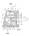
- the insulating housing of the plug or the plug coupling consists of the base body 2, which is designed as a holder for the plug pins 1 or the sockets 1 ', and the cover cap 3 covering the line connections 4 on the base body 2.
- the plug or the coupling is provided with an overall 5 designated strain relief device for the electrical lead, not shown.
- the electrical supply line can be inserted through the lateral recess 6 of the cover cap 3 into the interior of the connector housing.
- the strain relief device 5 consists of a support base 7 arranged on the base body 2 and a strain relief clamp 8 which can be braced against the support base 7.
- the strain relief clamp 8 passes through the outer wall of the housing, its rear side 39 facing away from the support base 7 forming part of the outer surface of the housing (Fig.
- the strain relief clamp 8 is guided in a longitudinal guide formed by the base body 2 and running in the tensioning direction 9. At least the part of the strain relief clamp 8 adjoining its rear wall 39 is arranged displaceably within a shaft 10, the side walls 11 of which are formed from housing insulating material, more precisely from the material of the base body 2.
- an edge earthing bracket 12 fastened to the base body 2 forms a limit stop which protrudes into the displacement path of the strain relief clamp 8 against the direction of tension 9.
- the inside 13 of the base body base 14 carries an approximately portal-shaped - in relation to the portal shape upside down - construction part 15 (Fig. 3.8), which forms the support base 7 for the electrical lead, not shown.
- the strain relief clamp 8 is with its pressure part 16 against the inside of the portal arch of the mounting part 15, i.e. thus can be braced against the support base 7 in the tensioning direction 9.
- the two portal columns 17, 18 of the structural part 15 are each in their longitudinal direction in the longitudinal direction of the plug pins 1 or sockets 1 'of one from the underside of the portal, i.e. with respect to FIGS. 3 and 8, screwed through from above tension screw 19 and 20 for the strain relief clamp 8.
- the screw heads 21 of the clamping screws 19, 20 are arranged recessed in the mounting part 15.
- the strain relief clamp 8 has the cross-sectional shape of an inverted T, for example.
- the vertical leg 22 of the T (FIG. 3.8) is located as a pressure part 16 between the portal columns 17, 18 of the mounting part 15.
- the two clamping screws 19, 20 are in the two horizontal leg parts 23 of the strain relief clamp 8 lying next to the vertical leg 22 from the vertical leg side screwable here.
- the pressure part 16 of the strain relief clamp 8 which acts on the electrical supply line is hollow (not shown in FIG. 3) and faces the load side, i.e. open to the shelf 7.
- the plug or the plug coupling is designed as an angular plug connection with a feed line (recess 6) inserted approximately at right angles to the insertion direction.
- the base body base 14 is provided on a side lying next to the plug level spanned by the two plug pins 1 or sockets 1 'with the recess designed as a shaft 10 for receiving the strain relief clamp 8.
- the shaft exit is bridged by the part of the edge earthing bracket 12 lying on or in the base body base 14.
- the base body base 14 is provided on its inside with a partition wall 24 which runs parallel to the plug level, projects into the interior of the housing and lies between the plug level and the displacement path (direction of tension 9) of the strain relief clamp 8.
- the upper edge of the partition is hollowed out in the connector analogous to the surface of the pressure part 16 of the strain relief clamp 8.
- screwing of base body 2 and cover cap 3 is a mounting screw 25 in the not provided with the shaft recess (shaft 10).
- the screw head 26 of the mounting screw rests on the edge earthing bracket 12, which in turn lies in a recess on the outside of the base body base 14.
- the portal level of the mounting part 15 runs approximately parallel to the plug level next to this.
- the insertion opening (recess 6) for the electrical supply line is arranged in the wall area of the cover cap 3 lying next to the structural part 15.
- the base body base 14 is provided on its inside with an inwardly projecting sleeve 28 containing the screw-in hole 27 for the mounting screw 25.
- the base body 2 contains, in addition to the sleeve 28 between this and the adjacent side wall of the cover cap 3, a wall reinforcement 29, on the back of which the edge earthing clip rests with its end 30 (FIG. 1).
- the grounding screw 31 of the electrical feed line can be screwed into the wall reinforcement 29. The screwing direction is directed against the tensioning direction 9.
- a tab 14 is formed on the side of the edge earthing bracket 12, which is bent in the tensioning direction 9 and extends through the base body base 14. The free end of this tab is penetrated by the grounding screw 31 in a plane parallel to the plug plane in the direction perpendicular to the tensioning direction 9.
- the protruding height of the grounding screw 31 over the inside of the base body base 14 is substantially smaller than the corresponding protruding height of the mounting part 15.
- the substantially flat base 32 of the cover cap 3 forms an acute angle 33 (Fig. 4.6), one leg of which, with the plug level 34 is inclined towards the side of the grounding screw 31 away from the plug level.
- the Zwi extending from the plane of the base body 14 in the bracing direction 9 cantilever walls 41 each form, together with the partition 24, a cuboid-shaped, open-top receiving space 42 for the connecting device 43.
- This consists in each case of the socket 1 ', a connecting bracket 44 and the connecting screw 45.
- the connecting bracket 44 rests on three sides on the inner wall of the receiving space 42 , it is penetrated from the side of the grounding screw 31 together with the adjacent intermediate wall 41 by the connecting screw 45.
- the free ends 46 of the connecting bracket 44 are bent towards each other and form the socket 1 '.
- the design of the strain relief device according to the invention can also be implemented in the same way for a plug or a plug coupling which is designed as a central plug or a central coupling socket. Then, however, the direction of tension 9 of the strain relief clamp 8 runs at right angles to the plug level. Then a part of the edge earthing bracket 12 lying outside the base body base 14 projects into the displacement path of the strain relief clamp 8 and forms the captive device or the limit stop there.
Landscapes
- Details Of Connecting Devices For Male And Female Coupling (AREA)
- Coupling Device And Connection With Printed Circuit (AREA)
- Joints Allowing Movement (AREA)
- Pens And Brushes (AREA)
- Mechanical Coupling Of Light Guides (AREA)
- Connector Housings Or Holding Contact Members (AREA)
Priority Applications (1)
| Application Number | Priority Date | Filing Date | Title |
|---|---|---|---|
| AT85102371T ATE56108T1 (de) | 1984-03-30 | 1985-03-02 | Stecker oder steckerkupplung mit zugentlastungseinrichtung. |
Applications Claiming Priority (2)
| Application Number | Priority Date | Filing Date | Title |
|---|---|---|---|
| DE19848409829U DE8409829U1 (de) | 1984-03-30 | 1984-03-30 | Stecker oder steckerkupplung mit zugentlastungseinrichtung |
| DE8409829U | 1984-03-30 |
Publications (3)
| Publication Number | Publication Date |
|---|---|
| EP0156189A2 true EP0156189A2 (fr) | 1985-10-02 |
| EP0156189A3 EP0156189A3 (en) | 1987-04-29 |
| EP0156189B1 EP0156189B1 (fr) | 1990-08-29 |
Family
ID=6765343
Family Applications (1)
| Application Number | Title | Priority Date | Filing Date |
|---|---|---|---|
| EP85102371A Expired - Lifetime EP0156189B1 (fr) | 1984-03-30 | 1985-03-02 | Fiche ou prise de courant avec un dispositif de décharge de la traction |
Country Status (5)
| Country | Link |
|---|---|
| EP (1) | EP0156189B1 (fr) |
| AT (1) | ATE56108T1 (fr) |
| DE (2) | DE8409829U1 (fr) |
| ES (1) | ES295811Y (fr) |
| GR (1) | GR850764B (fr) |
Cited By (1)
| Publication number | Priority date | Publication date | Assignee | Title |
|---|---|---|---|---|
| GB2235829A (en) * | 1989-08-04 | 1991-03-13 | Data Cable Co Inc | Strain relief cable fastener |
Family Cites Families (3)
| Publication number | Priority date | Publication date | Assignee | Title |
|---|---|---|---|---|
| DE1183153B (de) * | 1962-06-22 | 1964-12-10 | Busch Jaeger Duerener Metall | Schutzkontaktstecker mit quergeteiltem Steckerkoerper |
| US3335395A (en) * | 1965-03-19 | 1967-08-08 | Westinghouse Electric Corp | Angle plug |
| DE2048507A1 (de) * | 1970-10-02 | 1972-04-06 | Sel | Steckergehause |
-
1984
- 1984-03-30 DE DE19848409829U patent/DE8409829U1/de not_active Expired
-
1985
- 1985-03-02 AT AT85102371T patent/ATE56108T1/de not_active IP Right Cessation
- 1985-03-02 EP EP85102371A patent/EP0156189B1/fr not_active Expired - Lifetime
- 1985-03-02 DE DE8585102371T patent/DE3579336D1/de not_active Expired - Fee Related
- 1985-03-27 GR GR850764A patent/GR850764B/el unknown
- 1985-03-29 ES ES1985295811U patent/ES295811Y/es not_active Expired
Cited By (1)
| Publication number | Priority date | Publication date | Assignee | Title |
|---|---|---|---|---|
| GB2235829A (en) * | 1989-08-04 | 1991-03-13 | Data Cable Co Inc | Strain relief cable fastener |
Also Published As
| Publication number | Publication date |
|---|---|
| EP0156189A3 (en) | 1987-04-29 |
| DE3579336D1 (de) | 1990-10-04 |
| ES295811U (es) | 1987-06-16 |
| ES295811Y (es) | 1987-12-16 |
| GR850764B (fr) | 1985-11-25 |
| ATE56108T1 (de) | 1990-09-15 |
| DE8409829U1 (de) | 1984-09-27 |
| EP0156189B1 (fr) | 1990-08-29 |
Similar Documents
| Publication | Publication Date | Title |
|---|---|---|
| DE69212896T2 (de) | Schraubenbefestigter Steckverbinder | |
| DE19959185A1 (de) | Kabeldurchführung | |
| DE4134004C2 (de) | Anschlußklemme mit unverlierbarer Schraube und Klemmleiste mit derartigen Klemmen | |
| EP0156189B1 (fr) | Fiche ou prise de courant avec un dispositif de décharge de la traction | |
| EP0727850A2 (fr) | Dispositif pour le positionnement d'un composant électrique ou électronique dans une boîte | |
| DE4411731B4 (de) | Aufputz-Steckdose | |
| EP0294568A2 (fr) | Boîter de prises | |
| DE1790263C3 (de) | Verteilergehäuse mit einem Steckdoseneinsatz, z.B. einem mehrpoligen Wandsteckdoseneinsatz mit Schutzkontakt | |
| DE69301409T2 (de) | Element eines elektrischen Verbinders | |
| DE1880778U (de) | Kraftsteckdose. | |
| DE3634272C1 (en) | Arrangement for the longitudinal fixing of the inner conductor, with respect to the outer conductor, of a coaxial cable for broadband (wideband) communications systems | |
| DE3011762C2 (de) | Mehrpolige Kragensteckvorrichtung | |
| EP0257601B1 (fr) | Appareil d'installation électrique | |
| DE2856829C2 (de) | Steckverbinder mit durch eine Schraubenverbindung in einem Gehäuse befestigten Kontaktelementträger | |
| DE8030672U1 (de) | Vorrichtung zur Befestigung und Aufhängung von Kabelrinnen | |
| DE10359250A1 (de) | Steckverbinder, insbesondere zur Kontaktierung einer Leiterplatte | |
| DE8331968U1 (de) | Verbindungsvorrichtung fuer moebelwandungen | |
| DE2018529C (de) | Gehäuse für eine Glühlampe | |
| DE8119046U1 (de) | Schalter-Steckerkombination | |
| DE903832C (de) | Anschlussmuffe | |
| DE1943973U (de) | Freileitungsabzweigklemme. | |
| DE9405027U1 (de) | Schutzkontaktkupplung | |
| DE29807623U1 (de) | Steckdose sowie Kontakt für die Steckdose | |
| DE2232970A1 (de) | Anschlagteil fuer die festlegung einer gruppe von nebeneinander auf einer tragschiene angeordneten elementen | |
| DE7013199U (de) | Schutzkontaktstecker (oder -steckerkupplung). |
Legal Events
| Date | Code | Title | Description |
|---|---|---|---|
| PUAI | Public reference made under article 153(3) epc to a published international application that has entered the european phase |
Free format text: ORIGINAL CODE: 0009012 |
|
| AK | Designated contracting states |
Designated state(s): AT BE CH DE FR IT LI LU NL SE |
|
| ITCL | It: translation for ep claims filed |
Representative=s name: RICCARDI SERGIO & CO. |
|
| EL | Fr: translation of claims filed | ||
| TCNL | Nl: translation of patent claims filed | ||
| PUAL | Search report despatched |
Free format text: ORIGINAL CODE: 0009013 |
|
| AK | Designated contracting states |
Kind code of ref document: A3 Designated state(s): AT BE CH DE FR IT LI LU NL SE |
|
| 17P | Request for examination filed |
Effective date: 19871026 |
|
| 17Q | First examination report despatched |
Effective date: 19900115 |
|
| GRAA | (expected) grant |
Free format text: ORIGINAL CODE: 0009210 |
|
| AK | Designated contracting states |
Kind code of ref document: B1 Designated state(s): AT BE CH DE FR IT LI LU NL SE |
|
| PG25 | Lapsed in a contracting state [announced via postgrant information from national office to epo] |
Ref country code: SE Free format text: THE PATENT HAS BEEN ANNULLED BY A DECISION OF A NATIONAL AUTHORITY Effective date: 19900829 Ref country code: NL Effective date: 19900829 Ref country code: IT Free format text: LAPSE BECAUSE OF FAILURE TO SUBMIT A TRANSLATION OF THE DESCRIPTION OR TO PAY THE FEE WITHIN THE PRESCRIBED TIME-LIMIT;WARNING: LAPSES OF ITALIAN PATENTS WITH EFFECTIVE DATE BEFORE 2007 MAY HAVE OCCURRED AT ANY TIME BEFORE 2007. THE CORRECT EFFECTIVE DATE MAY BE DIFFERENT FROM THE ONE RECORDED. Effective date: 19900829 Ref country code: FR Effective date: 19900829 Ref country code: BE Effective date: 19900829 |
|
| REF | Corresponds to: |
Ref document number: 56108 Country of ref document: AT Date of ref document: 19900915 Kind code of ref document: T |
|
| REF | Corresponds to: |
Ref document number: 3579336 Country of ref document: DE Date of ref document: 19901004 |
|
| EN | Fr: translation not filed | ||
| NLV1 | Nl: lapsed or annulled due to failure to fulfill the requirements of art. 29p and 29m of the patents act | ||
| PG25 | Lapsed in a contracting state [announced via postgrant information from national office to epo] |
Ref country code: LU Free format text: LAPSE BECAUSE OF NON-PAYMENT OF DUE FEES Effective date: 19910331 |
|
| PLBE | No opposition filed within time limit |
Free format text: ORIGINAL CODE: 0009261 |
|
| STAA | Information on the status of an ep patent application or granted ep patent |
Free format text: STATUS: NO OPPOSITION FILED WITHIN TIME LIMIT |
|
| 26N | No opposition filed | ||
| PGFP | Annual fee paid to national office [announced via postgrant information from national office to epo] |
Ref country code: CH Payment date: 19930419 Year of fee payment: 9 |
|
| PGFP | Annual fee paid to national office [announced via postgrant information from national office to epo] |
Ref country code: AT Payment date: 19940329 Year of fee payment: 10 |
|
| PG25 | Lapsed in a contracting state [announced via postgrant information from national office to epo] |
Ref country code: LI Effective date: 19940331 Ref country code: CH Effective date: 19940331 |
|
| PGFP | Annual fee paid to national office [announced via postgrant information from national office to epo] |
Ref country code: DE Payment date: 19941020 Year of fee payment: 10 |
|
| REG | Reference to a national code |
Ref country code: CH Ref legal event code: PL |
|
| PG25 | Lapsed in a contracting state [announced via postgrant information from national office to epo] |
Ref country code: AT Effective date: 19950302 |
|
| PG25 | Lapsed in a contracting state [announced via postgrant information from national office to epo] |
Ref country code: DE Effective date: 19951201 |