EP0156323A2 - Hydraulische Druckregeleinrichtung zur Verwendung in Antiblockier-Bremssystemen - Google Patents
Hydraulische Druckregeleinrichtung zur Verwendung in Antiblockier-Bremssystemen Download PDFInfo
- Publication number
- EP0156323A2 EP0156323A2 EP85103372A EP85103372A EP0156323A2 EP 0156323 A2 EP0156323 A2 EP 0156323A2 EP 85103372 A EP85103372 A EP 85103372A EP 85103372 A EP85103372 A EP 85103372A EP 0156323 A2 EP0156323 A2 EP 0156323A2
- Authority
- EP
- European Patent Office
- Prior art keywords
- passage
- directional control
- pressure
- fluid
- master cylinder
- Prior art date
- Legal status (The legal status is an assumption and is not a legal conclusion. Google has not performed a legal analysis and makes no representation as to the accuracy of the status listed.)
- Granted
Links
- 239000012530 fluid Substances 0.000 claims abstract description 84
- 230000005284 excitation Effects 0.000 description 7
- 238000010586 diagram Methods 0.000 description 4
- 238000010276 construction Methods 0.000 description 2
- 230000004048 modification Effects 0.000 description 2
- 238000012986 modification Methods 0.000 description 2
- 230000001133 acceleration Effects 0.000 description 1
- 230000000881 depressing effect Effects 0.000 description 1
- 230000000994 depressogenic effect Effects 0.000 description 1
- 230000001771 impaired effect Effects 0.000 description 1
- 230000007935 neutral effect Effects 0.000 description 1
Images


Classifications
-
- B—PERFORMING OPERATIONS; TRANSPORTING
- B60—VEHICLES IN GENERAL
- B60T—VEHICLE BRAKE CONTROL SYSTEMS OR PARTS THEREOF; BRAKE CONTROL SYSTEMS OR PARTS THEREOF, IN GENERAL; ARRANGEMENT OF BRAKING ELEMENTS ON VEHICLES IN GENERAL; PORTABLE DEVICES FOR PREVENTING UNWANTED MOVEMENT OF VEHICLES; VEHICLE MODIFICATIONS TO FACILITATE COOLING OF BRAKES
- B60T8/00—Arrangements for adjusting wheel-braking force to meet varying vehicular or ground-surface conditions, e.g. limiting or varying distribution of braking force
- B60T8/32—Arrangements for adjusting wheel-braking force to meet varying vehicular or ground-surface conditions, e.g. limiting or varying distribution of braking force responsive to a speed condition, e.g. acceleration or deceleration
- B60T8/34—Arrangements for adjusting wheel-braking force to meet varying vehicular or ground-surface conditions, e.g. limiting or varying distribution of braking force responsive to a speed condition, e.g. acceleration or deceleration having a fluid pressure regulator responsive to a speed condition
- B60T8/50—Arrangements for adjusting wheel-braking force to meet varying vehicular or ground-surface conditions, e.g. limiting or varying distribution of braking force responsive to a speed condition, e.g. acceleration or deceleration having a fluid pressure regulator responsive to a speed condition having means for controlling the rate at which pressure is reapplied to or released from the brake
- B60T8/5012—Pressure reapplication using a plurality of valves in parallel
-
- B—PERFORMING OPERATIONS; TRANSPORTING
- B60—VEHICLES IN GENERAL
- B60T—VEHICLE BRAKE CONTROL SYSTEMS OR PARTS THEREOF; BRAKE CONTROL SYSTEMS OR PARTS THEREOF, IN GENERAL; ARRANGEMENT OF BRAKING ELEMENTS ON VEHICLES IN GENERAL; PORTABLE DEVICES FOR PREVENTING UNWANTED MOVEMENT OF VEHICLES; VEHICLE MODIFICATIONS TO FACILITATE COOLING OF BRAKES
- B60T8/00—Arrangements for adjusting wheel-braking force to meet varying vehicular or ground-surface conditions, e.g. limiting or varying distribution of braking force
- B60T8/32—Arrangements for adjusting wheel-braking force to meet varying vehicular or ground-surface conditions, e.g. limiting or varying distribution of braking force responsive to a speed condition, e.g. acceleration or deceleration
- B60T8/34—Arrangements for adjusting wheel-braking force to meet varying vehicular or ground-surface conditions, e.g. limiting or varying distribution of braking force responsive to a speed condition, e.g. acceleration or deceleration having a fluid pressure regulator responsive to a speed condition
- B60T8/50—Arrangements for adjusting wheel-braking force to meet varying vehicular or ground-surface conditions, e.g. limiting or varying distribution of braking force responsive to a speed condition, e.g. acceleration or deceleration having a fluid pressure regulator responsive to a speed condition having means for controlling the rate at which pressure is reapplied to or released from the brake
- B60T8/5018—Pressure reapplication using restrictions
- B60T8/5025—Pressure reapplication using restrictions in hydraulic brake systems
- B60T8/5037—Pressure reapplication using restrictions in hydraulic brake systems closed systems
Definitions
- the present invention relates generally to a hydraulic pressure control device in a vehicle anti-skid braking system, and more particularly to such a hydraulic pressure control device with means for giving the vehicle driver a smoother braking feeling at the time of starting to brake the vehicle.
- FIG. 1 of the accompanying drawings illustrates a conventional anti-skid control system (as disclosed in U.S. Patent No. 3,948,568) including a master cylinder 1, brake actuating cylinders 2 for braking vehicle wheels, and directional control valves 4 disposed in pipes between the master cylinder 1 and the brake actuating cylinders 2.
- the directional control valves 4 serve to control the braking fluid pressure in pressure-increasing, pressure-decreasing, and pressure-maintaining modes.
- each of the pipes connected to the directional control valves 4 has a restriction 5, or alternatively the directional control valves 4 have respective restrictions therein instead of the restrictions 5.
- each of the restrictions 5 tends to bring about an abrupt pressure buildup in the master cylinder 1 before a piston 8 therein moves past a port 12 leading to a fluid supply tank 10 right after a brake pedal 6 has started to be depressed by the driver. Therfore, the driver suffers a bad braking feeling when he starts braking the wheels.
- the fluid discharged from the brake actuating cylinders 2 and pumped back to the master cylinder 1 acts on the brake pedal 6 as a kickback.
- a hydraulic pressure control device in a vehicle anti-skid braking system comprising a brake master cylinder, a wheel brake actuating cylinder for braking a vehicle wheel, a master cylinder passage extending from the master cylinder, a fluid pressure supply passage connected between the master cylinder passage and the wheel brake actuating cylinder, a restriction disposed in the fluid pressure supply passage, a first directional control valve disposed in the fluid pressure supply passage and having at least pressure-increasing and pressure-decreasing modes, the first directional control valve being normally in the pressure-increasing mode to connect the master cylinder passage to the fluid pressure supply passage, a fluid pressure return passage connected to the first directional control valve, a second directional control valve connected between the master cylinder passage and the wheel brake actuating cylinder, the second directional control valve being normally open to provide a bypass passage across the first directional control valve to connect the master cylinder passage to the wheel brake actuating cylinder, and a control unit responsive to
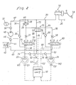
- the master cylinder 16 has a first hydraulic pressure generating chamber (not shown) connected through a pipe 20 to brake actuating cylinders 22, 24 for front wheels Wl, W2.
- the master cylinder 16 also has a second hydraulic pressure generating chamber (not shown) connected through a pipe 26 to brake actuating cylinders for rear wheels (not shown). More specifically, the pipe 20 is branched into a supply pipe 28 and a return pipe 30.
- the supply pipe 28 is connected through a pressure control valve 29, a restriction 31, a directional control valve 32, and a pipe 34 to the brake actuating cylinder'22.
- a restriction (not shown) may be provided in the directional control valve 32.
- the return pipe 30 is coupled through a check valve 36 and the pipe 34 to the brake actuating cylinder 22, the check valve 36 allowing the fluid to flow only in a direction from the brake actuating cylinder 22 to the master cylinder 16.
- a pipe 38 is connected to the directional control valve 32 and also connected through a pipe 40, a reservoir 42, a pipe 44, a check valve 46, a hydraulic pressure pump 48, a check valve 50, and a return pipe 47 to a port of the pressure control valve 29.
- An accumulator 51 is coupled to the return pipe 47.
- the check valves 46, 50 are oriented such that they permit a fluid flow only in the direction from the reservoir 42 to the pressure control valve 29.
- the pressure control valve 29 is of a construction similar to a spring-biased ball check valve having an inlet port connected via the supply pipe 28 to the pipe 29, annother inlet port connected to the return pipe 47, an outlet port connected to the restriction 31.
- the pressure control valve 29 also as a spring-biased ball 49 which normally allows fluid communication between the pipe 20 and its outlet port, but shuts off fluid communication between the return pipe 47 and the outlet port thereof.
- the directional control valve 32 is a spring-offset solenoid-operated valve of the three-port and three-position type.
- a solenoid 52 of the valve 32 When a high excitation current is passed through a solenoid 52 of the valve 32, the valve 32 is actuated to the leftmost or actuated position c against the bias of a spring 54 of the valve 32.
- a low excitation current When a low excitation current is supplied to the solenoid 52, the valve 32 is positioned in an intermediate position b.
- no excitation current flows through the solenoid 52 the valve 32 is biased to the rightmost or normal position a (as shown in FIG. 1) under the force of the spring 54.
- the directional control valve 32 When the directional control valve 32 is in the normal position a, the fluid under pressure is supplied from the master cylinder 16 to the brake actuating cylinder 22, which is in a pressure-increasing mode.
- the directional control valve 32 When the directional control valve 32 is in the actuated position c, no fluid is supplied from the master cylinder 16 through the directional control valve 32, but the fluid under pressure is discharged from the brake actuating cylinder 22 through the pipes 38, 40 into the reservoir 42. At this time, the wheel brake cylinder 22 is in a pressure-decreasing mode.
- the directional control valve 32 When the directional control valve 32 is in the intermediate position b, no fluid under pressure is supplied to and discharged from the brake actuating cylinder 22, which is in a pressure-maintaining mode.
- the levels of the excitation current are determined by a control signal issued from a control unit 55, described later.
- the brake actuating cylinder 24 is also connected to the master cylinder 16 through a return pipe 64 branched from the pipe 20, a check valve 66, and the pipe 62.
- a pipe 68 connected to the directional control valve 60 is connected through the pipe 40 to the reservoir 42.
- a restriction (not shown) may be provided in the directional control valve 60.
- a pipe 70 branched from the pipe 20 is connected through a directional control valve 72 to a pipe 74 which is branched into pipes 76, 78 coupled respectively through check valves 80, 82 to the pipes 62, 34.
- the pipes 70, 74, 76, 78 serve as bypass passages for the directional control valves 32, 60.
- the check valves 80, 82 are directed such that they allow a fluid to flow only in a direction from the pipe 74 to the brake actuating cylinders 22, 24.
- the directional control valve 72 comprises a spring-offset solenoid-operated valve of the two-port two-position type, having a solenoid 84 and a spring 86.
- the directional control valve 72 is biased by the spring 86 to provide fluid communication between the pipes 70, 74.
- the solenoid 84 is energized (at this time, one or both of the brake actuating cylinders 32, 60 are in either the pressure-decreasing mode or the pressure-maintaining mode, as described later)
- the directional control valve 72 is shifted to shut off any fluid communication between the pipes 70, 74.
- the brake actuating cylinders of the rear wheels are connected to the pipe 26 through substantially the same arrangement as that for the front wheels Wl, W2.
- Wheel speed sensors Dl, D2 are associated respectively with the front wheels Wl, W2.
- the wheel speed sensors Dl, D2 generate pulse signals having frequencies proportional to the speeds of rotation of the wheels Wl, W2 and apply such pulse signals to the control unit 55.
- the control unit 55 is responsive to the applied signals for computing wheel speeds, slip rates, decelerations to generate control signals Sl, S2, S3.
- the control signals Sl, S2 are supplied to the solenoids 52, 60, respectively, of the directional control valves 32, 60.
- the solenoid excitation currents are also of a high level.
- the soneoid excitation current are also of an intermediate level.
- control signals Sl, S2 When the control signals Sl, S2 are of a low level, then no solenoid excitation current is supplied. Therefore, when the control signals Sl, S2 are of high, intermediate, and low levels, the directional control valves 32, 60 are moved to the actuated position c, the intermediate position b, and the normal position a, respectively.
- the control signals Sl, S2 will be high in level when the fluid pressure in the brake actuating cylinders 22, 24 is to be reduced in the pressure-decreasing mode.
- the control signals Sl, S2 will be intermediate in level when the fluid pressure in the brake actuating cylinders 22, 24 is to be maintained in the pressure-maintaining mode.
- the control signals Sl, S2 will be low in level when the fluid pressure in the brake actuating cylinders 22, 24 is to be increased in the pressure-increasing mode.
- the control signal S3 also generated by the control unit 55 is applied to the solenoid 84 of the directional control valve 72.
- no control signal S3 is supplied to the solenoid 84 to allow the directional control valve 72 to provide fluid communication between the pipes 70, 74 under the bias of the spring 86.
- the control signal S3 is fed to the solenoid 84 to shift the directional control valve 72 for shutting off the pipes 70, 74.
- the directional control valves and the pressure control valve for the rear wheels are similarly controlled by the control unit 55 for braking the rear wheels.
- the control unit 55 of the above functions is of a simple conventional arrangement that could easily be achieved by those skilled in the art and hence will not be described in detail.
- the control unit 55 is responsive to detected signals from the wheel speed sensors Dl, D2 for determining that each wheel has not yet reached a prescribed deceleration and slip rate.
- the control signals Sl, S2 are therefore zero in level, and the directional control valves 32, 60 are in the normal position a.
- the directional control valve 72 is in the open position under the bias of the spring 84 to provide a fluid passage therethrough.
- the fluid pressure from the master cylinder 16 is applied through the pipe 20, the supply pipes 70, the directional control valve 72, the pipes 76, 78, the check valves 80, 82, the pipes 62, 34 to the brake actuating cylinders 22, 24 to thereby brake the front wheels Wl, W2.
- the braking fluid is prevented by the check valves 80, 82 from flowing back from the pipes 62, 34.
- the restrictions 31, 58 prevents the fluid from flowing through the directional control valves 32, 67 but causes the fluid to flow through the pipes 70, 74 and the directional control valve 72 which have a smaller resistance to fluid flow than the restrictions 31, 58.
- the brake pedal 18 is in its first stage of depression, any abrupt pressure buildup is prevented in the master cylinder 16, giving the driver a smooth brake feeling.
- the rear wheels are also braked in the same manner.
- the control signals Sl, S2 go high in level to shift the directional control valves 32, 60 toward the actuated position c in which the pipes 28, 34 and the pipes 56, 62 are disconnected, and the pipes 34, 38 and the pipes 62, 68 are connected.
- the brake actuating cylinders 22, 24 are now in the pressure-decreasing mode.
- the braking fluid now flows from the brake actuating cylinders 22, 24 through the pipes 34, 38, 62, 68, 40 into the reservoir 42.
- the fluid pressure pump 48 starts operating when either the control signal Sl or S2 reaches the high level, so that the braking fluid is drawn by the pump 48 from the reservoir 42, pressurized, and then delivered through the check valve 50 into the accumulator 51 and the pressure control valve 29 via the return pipe 47.
- the pressurized fluid is then supplied through the pressure control valve 29 to the directional control valves 32, 60, but not to the master cylinder 16. Therefore, the brake pedal 22 is not subjected to any kickback due to an unwanted pressure buildup in the pipe 20.
- the control unit 55 applies the control signal S3 to the solenoid 84, so that the directional control valve 72 is closed to shut off the pipes 70, 74. The same operation is carried out with respect to the rear wheels.
- the control signals Sl, S2 are at the low level to actuate the directional control valves 32, 60 into the intermediate or neutral position b.
- the pipes 28 and 34, 38 and the pipes 56 and 62, 68 are then disconnected.
- the braking fluid pressure now remains maintained at a constant level.
- the directional control valve 72 is in the shutoff position as described above. The above operation holds true for the rear wheels.
- the control signals Sl, S2 go low to shift the directional control valves 32, 60 to the actuated position a or the pressure-increasing mode.
- the pipes 28, 34 and the pipes 56, 62 are brought into communication to increase the braking force on the wheels Wl, W 2.
- the directional control valve 72 remains closed, and therefore, the fluid under pressure from the master cylinder 16 is supplied through the restrictions 31, 58 and the directional control valves 32, 60 to the brake actuating cylinders 22, 24.
- the rate at which the fluid pressure increases in the brake actuating cylinders 22, 24 is relatively low due to the restrictions 31, 58.
- the brake actuating cylinders 22, 24 are therefore not subjected to an abrupt pressure increase and can brake the wheels Wl, W2 under good control.
- the directional control valve 72 When one of the directional control valves 32, 60 is in the pressure-increasing mode and the other in one of the other mdoes, the directional control valve 72 is in the closed position, and the fluid under pressure from the master cylinder 16 is supplied through the restriction 31 or 58 to the directional control valve in the pressure-increasing mode. As a result, the fluid pressure in the master cylinder 16 builds up, but the driver is given no impaired brake feeling because the piston in the master cylinder 16 has already moved past a port connected to a fluid supply tank for the master cylinder 16. At this time, the rate of pressure buildup in the directional control valves 32, 60 is relatively low as the fluid is supplied thereto through the restrictions 31, 58.
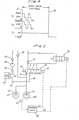
- FIG. 3 shows a fluid pressure control device according to another embodiment.
- a wheel speed sensor D3 is disposed between the wheels WI, W2 for detecting the speed of rotation of the front wheels Wl, W2 to control the single directional control valve 32 which is arranged to control the fluid pressure in each of the brake actuating cylinders 22, 24 for the wheels Wl, W2.
- FIG. 4 illustrates the manner in which the signals Sl, S2, S3 from the control unit 55 vary in level from the time A when the anti-skid control is started to the time B when the anti-skid control is ceased.
- the restriction 31 is shunted by the directional control valve 72, and the brake actuating cylinders 22, 24 are controlled by the single directional control valve 32.
- the check valves 80, 82 are dispensed with.
Landscapes
- Engineering & Computer Science (AREA)
- Physics & Mathematics (AREA)
- Fluid Mechanics (AREA)
- Transportation (AREA)
- Mechanical Engineering (AREA)
- Regulating Braking Force (AREA)
Applications Claiming Priority (2)
| Application Number | Priority Date | Filing Date | Title |
|---|---|---|---|
| JP59057130A JPS60199756A (ja) | 1984-03-23 | 1984-03-23 | アンチスキッド装置用液圧制御装置 |
| JP57130/84 | 1984-03-23 |
Publications (3)
| Publication Number | Publication Date |
|---|---|
| EP0156323A2 true EP0156323A2 (de) | 1985-10-02 |
| EP0156323A3 EP0156323A3 (en) | 1986-12-30 |
| EP0156323B1 EP0156323B1 (de) | 1990-08-08 |
Family
ID=13046973
Family Applications (1)
| Application Number | Title | Priority Date | Filing Date |
|---|---|---|---|
| EP85103372A Expired EP0156323B1 (de) | 1984-03-23 | 1985-03-22 | Hydraulische Druckregeleinrichtung zur Verwendung in Antiblockier-Bremssystemen |
Country Status (4)
| Country | Link |
|---|---|
| US (1) | US4636009A (de) |
| EP (1) | EP0156323B1 (de) |
| JP (1) | JPS60199756A (de) |
| DE (1) | DE3579019D1 (de) |
Cited By (7)
| Publication number | Priority date | Publication date | Assignee | Title |
|---|---|---|---|---|
| US4715667A (en) * | 1984-08-09 | 1987-12-29 | Nippondenso Co., Ltd. | Hydraulic pressure control device for use in vehicle anti-skid braking system |
| WO1989001431A1 (en) * | 1987-08-21 | 1989-02-23 | Allied-Signal Inc. | Anti-lock/traction control braking system with pressure operated isolation valves |
| FR2653400A1 (fr) * | 1989-10-23 | 1991-04-26 | Jidosha Kiki Co | Systeme de commande de freinage anti-blocage. |
| EP0437752A1 (de) * | 1990-01-16 | 1991-07-24 | Robert Bosch Gmbh | Hydraulische Bremsanlage für Fahrzeuge, insbesondere Kraftfahrzeuge |
| FR2670731A1 (fr) * | 1990-12-20 | 1992-06-26 | Bendix Europ Services Tech | Systeme d'anti-patinage pour vehicule automobile. |
| US5169214A (en) * | 1990-10-26 | 1992-12-08 | Robert Bosch Gmbh | Hydraulic multi-circuit brake system including a traction and anti-skid control device for motor vehicles |
| US5188435A (en) * | 1990-10-26 | 1993-02-23 | Robert Bosch Gmbh | Hydraulic anti-lock multicircuit brake system, for motor vehicles |
Families Citing this family (13)
| Publication number | Priority date | Publication date | Assignee | Title |
|---|---|---|---|---|
| JPS61218466A (ja) * | 1985-03-25 | 1986-09-27 | Nippon Denso Co Ltd | アンチスキツド制御装置 |
| US4755008A (en) * | 1985-12-25 | 1988-07-05 | Nippondenso Co., Ltd. | Braking system with power brake, braking force proportioning, anti-skid, and traction control functions |
| DE3624721A1 (de) * | 1986-07-22 | 1988-01-28 | Teves Gmbh Alfred | Bremsanlage mit blockierschutz- und antriebsschlupfregelung |
| DE3735366A1 (de) * | 1987-10-19 | 1989-05-03 | Teves Gmbh Alfred | Bremsschlupfgeregelte kraftfahrzeugbremsanlage |
| JP2669624B2 (ja) * | 1987-12-15 | 1997-10-29 | 株式会社ユニシアジェックス | アンチスキッドブレーキ装置 |
| DE3800854A1 (de) * | 1988-01-14 | 1989-07-27 | Bosch Gmbh Robert | Bremsanlage mit antiblockier- und antriebsschlupfregelung |
| US5011238A (en) * | 1990-03-19 | 1991-04-30 | Allied-Signal Inc. | Master cylinder with integrated adaptive braking and traction control system |
| DE4110528A1 (de) * | 1991-03-30 | 1992-10-01 | Teves Gmbh Alfred | Blockiergeschuetzte hydraulische bremsanlage |
| DE4127040B4 (de) * | 1991-08-16 | 2005-06-23 | Continental Teves Ag & Co. Ohg | Schlupfgeregelte Bremsanlage |
| JPH0834330A (ja) * | 1994-07-20 | 1996-02-06 | Nisshinbo Ind Inc | アンチスキッド制御装置及び制御方法 |
| FR2729866B1 (fr) * | 1995-01-30 | 1997-04-11 | Rossignol Sa | Perfectionnement aux skis a coque pourvus de chants de support de la coque |
| US5540488A (en) * | 1995-05-11 | 1996-07-30 | Aisin Seiki Kabushiki Kaisha | Hydraulic braking system having an auxiliary pressure source |
| US5673979A (en) * | 1995-06-01 | 1997-10-07 | Aisin Seiki Kabushiki Kaisha | Hydraulic braking pressure control apparatus for automotive vehicle |
Family Cites Families (6)
| Publication number | Priority date | Publication date | Assignee | Title |
|---|---|---|---|---|
| US3549212A (en) * | 1969-06-03 | 1970-12-22 | Teldix Gmbh | Anti-locking control system |
| JPS5541935B2 (de) * | 1973-05-29 | 1980-10-27 | ||
| DE2342307C2 (de) * | 1973-08-22 | 1984-12-20 | Robert Bosch Gmbh, 7000 Stuttgart | Anordnung zur Überprüfung eines Antiblockierregelsystems für Fahrzeugbremsanlagen |
| JPS5850903B2 (ja) * | 1975-08-14 | 1983-11-12 | ヤマハハツドウキ カブシキガイシヤ | アンチスキツドソウチ |
| US4099793A (en) * | 1976-08-12 | 1978-07-11 | Yamaha Hatsudoki Kabushiki Kaisha | Anti-skid vehicle brake system with fluid pressure actuated regulating valve |
| JPS5799446A (en) * | 1980-12-08 | 1982-06-21 | Nippon Air Brake Co Ltd | Fluid pressure controller for anti-skid devices |
-
1984
- 1984-03-23 JP JP59057130A patent/JPS60199756A/ja active Granted
-
1985
- 1985-03-22 DE DE8585103372T patent/DE3579019D1/de not_active Expired - Lifetime
- 1985-03-22 US US06/714,804 patent/US4636009A/en not_active Expired - Fee Related
- 1985-03-22 EP EP85103372A patent/EP0156323B1/de not_active Expired
Cited By (10)
| Publication number | Priority date | Publication date | Assignee | Title |
|---|---|---|---|---|
| US4715667A (en) * | 1984-08-09 | 1987-12-29 | Nippondenso Co., Ltd. | Hydraulic pressure control device for use in vehicle anti-skid braking system |
| WO1989001431A1 (en) * | 1987-08-21 | 1989-02-23 | Allied-Signal Inc. | Anti-lock/traction control braking system with pressure operated isolation valves |
| FR2653400A1 (fr) * | 1989-10-23 | 1991-04-26 | Jidosha Kiki Co | Systeme de commande de freinage anti-blocage. |
| EP0437752A1 (de) * | 1990-01-16 | 1991-07-24 | Robert Bosch Gmbh | Hydraulische Bremsanlage für Fahrzeuge, insbesondere Kraftfahrzeuge |
| US5169214A (en) * | 1990-10-26 | 1992-12-08 | Robert Bosch Gmbh | Hydraulic multi-circuit brake system including a traction and anti-skid control device for motor vehicles |
| US5188435A (en) * | 1990-10-26 | 1993-02-23 | Robert Bosch Gmbh | Hydraulic anti-lock multicircuit brake system, for motor vehicles |
| ES2049612A2 (es) * | 1990-10-26 | 1994-04-16 | Bosch Gmbh Robert | Instalacion de freno hidraulica, antibloqueo, de varios circuitos, especialmente para automoviles. |
| FR2670731A1 (fr) * | 1990-12-20 | 1992-06-26 | Bendix Europ Services Tech | Systeme d'anti-patinage pour vehicule automobile. |
| EP0495324A1 (de) * | 1990-12-20 | 1992-07-22 | Alliedsignal Europe Services Techniques | Antirutschsystem für Kraftfahrzeuge |
| US5188438A (en) * | 1990-12-20 | 1993-02-23 | Bendix Europe Services Techniques | Anti-skid system for a motor vehicle |
Also Published As
| Publication number | Publication date |
|---|---|
| EP0156323A3 (en) | 1986-12-30 |
| EP0156323B1 (de) | 1990-08-08 |
| JPH0436903B2 (de) | 1992-06-17 |
| US4636009A (en) | 1987-01-13 |
| JPS60199756A (ja) | 1985-10-09 |
| DE3579019D1 (de) | 1990-09-13 |
Similar Documents
| Publication | Publication Date | Title |
|---|---|---|
| US4636009A (en) | Hydraulic pressure control device for use in vehicle anti-skid braking system | |
| US4715667A (en) | Hydraulic pressure control device for use in vehicle anti-skid braking system | |
| US4840436A (en) | Anti-lock brake system with traction slip control | |
| GB2242492A (en) | Improvements in and relating to anti-lock brake systems | |
| US4603920A (en) | Hydraulic pressure control device for use in vehicle anti-skid braking system | |
| JPH04215551A (ja) | 車両用のブレーキ装置 | |
| US5584540A (en) | Hydraulic braking system for an automotive vehicle | |
| US5921638A (en) | Brake fluid pressure control device | |
| US6095622A (en) | Hydraulic brake control system for use in a vehicle | |
| GB2294989A (en) | A brake system | |
| US4796957A (en) | Vehicular drive control system | |
| US6092880A (en) | Integrated anti-skid and hydraulic booster braking control | |
| US5326160A (en) | Hydraulic systems for vehicles | |
| US5232272A (en) | Hydraulic brake system for avoiding high brake or traction slip values | |
| EP0503873B1 (de) | Bremssystem für Fahrzeuge | |
| JPH07102802B2 (ja) | トラクションスリップ制御付きブレーキシステム | |
| US5971502A (en) | Secondary braking control | |
| US5700069A (en) | Anti-skid control system for an automotive vehicle | |
| US6301541B1 (en) | Braking force control apparatus for vehicle | |
| WO1995015875A1 (en) | Low cost anti-lock braking system | |
| GB2242948A (en) | Hydraulic braking system for an automotive vehicle | |
| JPH1044959A (ja) | 車輌のアクティブブレーキ装置 | |
| JPH04231251A (ja) | アンチロック制御付液圧ブレーキシステム | |
| JP2765570B2 (ja) | 車両用ブレーキ制御装置 | |
| JPH09193766A (ja) | ブレーキ制御装置 |
Legal Events
| Date | Code | Title | Description |
|---|---|---|---|
| PUAI | Public reference made under article 153(3) epc to a published international application that has entered the european phase |
Free format text: ORIGINAL CODE: 0009012 |
|
| AK | Designated contracting states |
Designated state(s): DE FR GB |
|
| PUAL | Search report despatched |
Free format text: ORIGINAL CODE: 0009013 |
|
| AK | Designated contracting states |
Kind code of ref document: A3 Designated state(s): DE FR GB |
|
| 17P | Request for examination filed |
Effective date: 19870513 |
|
| 17Q | First examination report despatched |
Effective date: 19871117 |
|
| GRAA | (expected) grant |
Free format text: ORIGINAL CODE: 0009210 |
|
| AK | Designated contracting states |
Kind code of ref document: B1 Designated state(s): DE FR GB |
|
| ET | Fr: translation filed | ||
| REF | Corresponds to: |
Ref document number: 3579019 Country of ref document: DE Date of ref document: 19900913 |
|
| REG | Reference to a national code |
Ref country code: GB Ref legal event code: 746 |
|
| PLBE | No opposition filed within time limit |
Free format text: ORIGINAL CODE: 0009261 |
|
| STAA | Information on the status of an ep patent application or granted ep patent |
Free format text: STATUS: NO OPPOSITION FILED WITHIN TIME LIMIT |
|
| 26N | No opposition filed | ||
| PGFP | Annual fee paid to national office [announced via postgrant information from national office to epo] |
Ref country code: DE Payment date: 19950322 Year of fee payment: 11 |
|
| PGFP | Annual fee paid to national office [announced via postgrant information from national office to epo] |
Ref country code: FR Payment date: 19960126 Year of fee payment: 12 |
|
| PGFP | Annual fee paid to national office [announced via postgrant information from national office to epo] |
Ref country code: GB Payment date: 19960313 Year of fee payment: 12 |
|
| PG25 | Lapsed in a contracting state [announced via postgrant information from national office to epo] |
Ref country code: DE Effective date: 19961203 |
|
| PG25 | Lapsed in a contracting state [announced via postgrant information from national office to epo] |
Ref country code: GB Effective date: 19970322 |
|
| GBPC | Gb: european patent ceased through non-payment of renewal fee |
Effective date: 19970322 |
|
| PG25 | Lapsed in a contracting state [announced via postgrant information from national office to epo] |
Ref country code: FR Free format text: LAPSE BECAUSE OF NON-PAYMENT OF DUE FEES Effective date: 19971128 |
|
| REG | Reference to a national code |
Ref country code: FR Ref legal event code: ST |