EP0156441A2 - Mantel für Brückenkabel - Google Patents
Mantel für Brückenkabel Download PDFInfo
- Publication number
- EP0156441A2 EP0156441A2 EP85200454A EP85200454A EP0156441A2 EP 0156441 A2 EP0156441 A2 EP 0156441A2 EP 85200454 A EP85200454 A EP 85200454A EP 85200454 A EP85200454 A EP 85200454A EP 0156441 A2 EP0156441 A2 EP 0156441A2
- Authority
- EP
- European Patent Office
- Prior art keywords
- cover
- cable
- divided
- trough
- armor
- Prior art date
- Legal status (The legal status is an assumption and is not a legal conclusion. Google has not performed a legal analysis and makes no representation as to the accuracy of the status listed.)
- Granted
Links
- 125000006850 spacer group Chemical group 0.000 claims abstract description 31
- 229910000831 Steel Inorganic materials 0.000 claims abstract description 25
- 239000010959 steel Substances 0.000 claims abstract description 25
- 239000002184 metal Substances 0.000 claims abstract 3
- 238000003780 insertion Methods 0.000 abstract description 3
- 230000037431 insertion Effects 0.000 abstract description 3
- 238000000034 method Methods 0.000 description 8
- 239000000725 suspension Substances 0.000 description 7
- 229920003002 synthetic resin Polymers 0.000 description 7
- 239000000057 synthetic resin Substances 0.000 description 7
- 239000004698 Polyethylene Substances 0.000 description 5
- -1 polyethylene Polymers 0.000 description 5
- 229920000573 polyethylene Polymers 0.000 description 5
- 239000011248 coating agent Substances 0.000 description 3
- 238000000576 coating method Methods 0.000 description 3
- 238000005452 bending Methods 0.000 description 2
- 238000010276 construction Methods 0.000 description 2
- 230000000694 effects Effects 0.000 description 2
- 239000000945 filler Substances 0.000 description 2
- 239000000463 material Substances 0.000 description 2
- 238000010422 painting Methods 0.000 description 2
- 230000000704 physical effect Effects 0.000 description 2
- XAGFODPZIPBFFR-UHFFFAOYSA-N aluminium Chemical compound [Al] XAGFODPZIPBFFR-UHFFFAOYSA-N 0.000 description 1
- 229910052782 aluminium Inorganic materials 0.000 description 1
- 239000004568 cement Substances 0.000 description 1
- 238000002347 injection Methods 0.000 description 1
- 239000007924 injection Substances 0.000 description 1
- 239000000203 mixture Substances 0.000 description 1
- 238000007747 plating Methods 0.000 description 1
- 230000001681 protective effect Effects 0.000 description 1
- 229920005989 resin Polymers 0.000 description 1
- 239000011347 resin Substances 0.000 description 1
- XLYOFNOQVPJJNP-UHFFFAOYSA-N water Substances O XLYOFNOQVPJJNP-UHFFFAOYSA-N 0.000 description 1
- 238000003466 welding Methods 0.000 description 1
Images


Classifications
-
- E—FIXED CONSTRUCTIONS
- E01—CONSTRUCTION OF ROADS, RAILWAYS, OR BRIDGES
- E01D—CONSTRUCTION OF BRIDGES, ELEVATED ROADWAYS OR VIADUCTS; ASSEMBLY OF BRIDGES
- E01D19/00—Structural or constructional details of bridges
- E01D19/16—Suspension cables; Cable clamps for suspension cables ; Pre- or post-stressed cables
-
- Y—GENERAL TAGGING OF NEW TECHNOLOGICAL DEVELOPMENTS; GENERAL TAGGING OF CROSS-SECTIONAL TECHNOLOGIES SPANNING OVER SEVERAL SECTIONS OF THE IPC; TECHNICAL SUBJECTS COVERED BY FORMER USPC CROSS-REFERENCE ART COLLECTIONS [XRACs] AND DIGESTS
- Y10—TECHNICAL SUBJECTS COVERED BY FORMER USPC
- Y10T—TECHNICAL SUBJECTS COVERED BY FORMER US CLASSIFICATION
- Y10T24/00—Buckles, buttons, clasps, etc.
- Y10T24/44—Clasp, clip, support-clamp, or required component thereof
- Y10T24/44034—Dissociable gripping members
Definitions
- the present invention relates to a joint of a cover for coating bridge cable, and also to an armor for coating a bridge cable comprising a specified number of bundles of PC steel wires covered, for example, with polyethylene.
- the cover or tube is made of synthetic resin, it is deteriorated in a short period of time and the service life is short. Furthermore it is difficult to insert into the steel tube or into synthetic resin tube the stranded wires and the spacer to position the stranded wires, and the filler can not be injected smoothly.
- the invention provides a joint of a cable cover wherein a seal member is composed of a specified number of elastic trough-shaped divided bodies for covering the outer periphery of a cable cover by abutting against each other on the side edges thereof, protrusions projecting from the middle of the inside of the divided body for insertion between the facing end edges of the cable cover, and engaging parts projecting from both ends of the surface of the divided body, and a fixing tube is composed of trough-shaped divided covers each of which externally contacts with the divided body on the end edges facing the inside of the engaging parts and fixing parts for fixing the side edges against which the divided cover abuts in such a manner as to keep watertightness, and the seal member and the fixing tube is connected with eachg other so as to keep watertightness at the facing ends of the cable cover and also to keep the connection parts free of influence of expansion and shrinkage of the cable cover.
- the seal member is compressed by fitting the fixing tube to the outside of the seal member after putting both the ends of the seal member on the outer periphery of the facing ends of the cable cover, the watertightness of the connection parts may be kept extremely well, and any bad effect is not exerted on the joint part if the cable cover is elongated by a live load, or expands or shrinks due to temperature changes.
- a fitting process is easy because the seal member is formed in a trough-shape by the divided bodies which are of a specified number of sections and the fixing tube is also formed in a trough-shape by the divided covers which are of a specified number of divisions.
- This invention presents the armor for a bridge cable intended to prevent influence of ultraviolet rays, or wind and rain by covering a bridge cable comprising a specified number of bundles of PC steel wires with a trough-shaped divided covers in a specified number of divisions, and by installing an elastic spacer fitted and assembled inside the cover to maintain the cable shape, to absorb influence of impact and to temperature changes, and to reduce the cover in weight.
- the wall thickness is made uniform at both side edges of the cover by the use of the spacer, the weight is reduced, and the product may be presented at a lower price. Yet, since the spacer is inserted and fitted into the cover, slip-out of the spacer during work may be prevented.
- the spacer also serves to dissolve a difference between the cover and PC steel wire in bore.
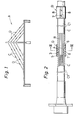
- Fig. 1 is a schematic view showing the joints of the invention being used in cable covers C for protecting cables B (see Fig. 2) in an oblique suspension bridge A, in which the cable covers C may be sequentially mounted on the cables B, or, as shown in Fig. 2, mounted thereon by dividing a tube body into two or more sections to form a trough-shaped covers Cl which may be fitted on the outer periphery of the cables B, and by thereafter fixing the fitted or butted side edges of these divided covers Cl in watertight state by field welding or mechanical joining or by other methods.
- the cable may be either an assembled group of a specified number of bundles of PC steel wires, or, as shown in Fig. 8, unbonded type PC steel stranded wires with a polyethylene sheath.
- Reference mark D denotes the joint to link the facing ends of the cable cover C.
- the joint D is composed of, as shown in Figs. 2 through 4, the combination of a seal member 6 which comprises divided bodies 3 made of an elastic tube body such as rubber which is divided into two or more sections in the circumferential direction and along the axial direction to externally contact with the outer periphery of the cable cover C at both ends thereof, protrusions 4 provided in the middle of both ends of the inside of this divided body 3 so as to fit between facing ends of the cable cover C, and engaging parts 5 projecting from both end edges of the surface of the divided body 3, and a fixing tube 8 which comprises trough-shaped divided covers 7 each externally contacting with the divided body 3 with the end edges facing the inside of the engaging parts 5, and fixing parts 9, 10 for fixing the butted side edges of this divided cover 7 so as to keep watertightness.
- a seal member 6 which comprises divided bodies 3 made of an elastic tube body such as rubber which is divided into two or more sections in the circumferential direction and along the axial direction to externally contact with the outer periphery of the cable cover C at both
- the fixing parts are inserted and joined to keep watertightness by forming sawtooth protrusions 9 and grooves 10 at both the sides of the divided cover 7, to be engaged with each other, but it may be also fixed by other method as in the cable cover C.
- Reference numeral 12 in Fig. 4 is a groove provided inside the divided body 3 for the side edge fixing parts of divided covers Cl, Cl to fit therein.
- the joint of the cable cover in this invention is thus composed, and the method of using this joint D is described below.
- the cable B is covered by the cable cover C.
- an interval equal to width 2 of the protrusion 4 is set between the facing endgs of the cable covers C, C arranged in series.
- both the ends of each divided body 3 are externally fitted to the cable covers C.
- the side edges of each divided body 3 are butted against each other.
- each divided cover 7 of the fixing tube 8 is fitted into the outside of the seal member 6 for length of 1 , and also the butted side edges of the divided cover 7 are fixed to keep watertightness.
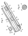
- a unit protective armor F for cable B assembled of a specified number of PC steel wires b in parallel arrangement is composed of two or more trough-shaped covers 30, and male fitting part 31 and female fitting part 32 provided on both sided edges of each of the covers 30 to be coupled with each other by insertion.
- the male fitting parts 31 and female fitting parts 32 are, as shown in Fig. 7, composed of grooves 32a and protrusions 31a to be pushed therein, and are intended to maintain a coupled state without allowing disengagement by causing the sawtooth concave and convex parts provided at both sides of the grooves 32a and protrusions 31a to mesh with each other.
- This spacer G is composed of an elastic plate 33 made of rubber or other soft synthetic resin, and parallel grooves 34 provided for part of the outer periphery of the PC steel wires b to fit into the surface of the elastic plate 33.
- the spacers G are disposed sporadically inside the cover 30 in the illustrated example, but it may be also provided for the entire length of the cover 30.
- parallel protrusions 35 having ' out parts at the front end edges thereof are integrally provided in the axial direction inside the cover 30, and grooves 36 in which the protrusions 35 fit are provided in the spacers G, and the grooves 36 are expanded by bending the spacers G to fit the grooves 36 to the protrusions 35 and thereafter by removing the bending of the spacers G, but in another embodiment, to obtain the same effect, grooves provided in the spacer 30 and protrusions formed on the spacer G are arranged to be fitted together.
- the cover 30 is made of an extruded form of aluminum, which is cut to a specified length for use.
- PC steel wires b those of unbonded type with polyethylene sheath 37 as shown in Fig. 8 are used.
- the armor of a bridge cable according to this invention is thus composed, and the method of protection of cable by using this armor F is described below.
- PC steel wires b in a specified length are arranged in parallel by a specified number of pieces to form a cable B, and the terminal ends of the calble B are fixed by a known method.
- the cable B is covered with the armor F for its overall length, and the butting ends of the armor F are connected by using a proper joint. Yet, in locations easily subjected to impacts from outside, longer spacers G or more number of spacers G are used.
- Fig. 9 is a sectional view of further another embodiment of this invention, in which same reference marks are given to parts corresponding to those used in the foregoing embodiment in Fig. 6.
- Wire bundles 41 of PC steel wires are wound with and tightened by a spiral wire rope 42 made of PC steel wires and are grouted, and are inserted into a tube body 44 made of polyethylene or other synthetic resin material, thus composing a cable B.
- Such cable B has been already utilized in the oblique suspension bridge under construction or in use, and in order to protect this cable B or for the purpose of beautification of appearance, the cable B is covered with a cover 30 through an elastic spacer Gl in accordance with the invention.
- the elastic spacer Gl is made of rubber or soft synthetic resin, and comprises a support part 45 which adheres to the outer periphery of a tube body 44 and another support part 46 which abuts against the inner periphery of the cover 30.
- a protrusion 47 extending in its axial direction is formed, and a groove 48 formed in the support part 46 fits with this protrusion 47.
- a plurality of the protrusions 47 and spacers Gl are provided in the circumferential direction of the covers 30 (four for each, in this embodiment).
- the spacers Gl may be sporadically disposed in the axial direction of the cover 30, or may extend continuously in the axial direction.
- the other structure of the cover 30 is same as in the foregoing embodiment.
- Fig. 10 is a sectional view of still another embodiment of this invention, which is similar to the embodiment disclosed in Fig. 9, wherein same reference marks are given to corresponding parts.
- the cable B in the oblique suspension bridge under construction or in use is composed of wire bundles 51 and a tube body 52 made of a synthetic resin material such as polyethylene externally surrounding them.
- Such cable B is also covered with the cover 30 by way of spacers Gl, so that not only the cable B is protected but also the appearance is enhanced.
Landscapes
- Engineering & Computer Science (AREA)
- Architecture (AREA)
- Civil Engineering (AREA)
- Structural Engineering (AREA)
- Bridges Or Land Bridges (AREA)
- Ropes Or Cables (AREA)
Applications Claiming Priority (2)
| Application Number | Priority Date | Filing Date | Title |
|---|---|---|---|
| JP1984044559U JPS60154405U (ja) | 1984-03-26 | 1984-03-26 | 橋梁ケ−ブルの外装材 |
| JP44559/84U | 1984-03-26 |
Publications (3)
| Publication Number | Publication Date |
|---|---|
| EP0156441A2 true EP0156441A2 (de) | 1985-10-02 |
| EP0156441A3 EP0156441A3 (en) | 1986-12-30 |
| EP0156441B1 EP0156441B1 (de) | 1989-09-27 |
Family
ID=12694853
Family Applications (1)
| Application Number | Title | Priority Date | Filing Date |
|---|---|---|---|
| EP85200454A Expired EP0156441B1 (de) | 1984-03-26 | 1985-03-22 | Mantel für Brückenkabel |
Country Status (4)
| Country | Link |
|---|---|
| US (1) | US4612680A (de) |
| EP (1) | EP0156441B1 (de) |
| JP (1) | JPS60154405U (de) |
| DE (1) | DE3573283D1 (de) |
Cited By (5)
| Publication number | Priority date | Publication date | Assignee | Title |
|---|---|---|---|---|
| EP0323285A1 (de) * | 1987-11-25 | 1989-07-05 | Freyssinet International (Stup) | Schrägseile und deren Verankerung |
| DE4319888A1 (de) * | 1993-06-16 | 1995-01-05 | Dyckerhoff & Widmann Ag | Rohrförmige Ummantelung für ein Zugglied |
| CN106120557A (zh) * | 2010-03-26 | 2016-11-16 | Vsl国际股份公司 | 线股引导装置的改进 |
| EP3097619A4 (de) * | 2014-01-22 | 2017-08-02 | 3M Innovative Properties Company | Gehäuse für eine kabelverbindung |
| CN112927845A (zh) * | 2021-02-01 | 2021-06-08 | 浙江正泰电缆有限公司 | 一种阻水电力电缆及其制造方法 |
Families Citing this family (55)
| Publication number | Priority date | Publication date | Assignee | Title |
|---|---|---|---|---|
| US4997148A (en) * | 1988-12-20 | 1991-03-05 | Zsi, Inc. | Tubing clamp with hinged cushion |
| US4934635A (en) * | 1988-12-20 | 1990-06-19 | Zsi, Inc. | Tubing clamp with hinged cushion |
| DE59001339D1 (de) * | 1989-04-12 | 1993-06-09 | Vorspann Technik Gmbh | Spannbuendel aus mehreren spanngliedern wie litzen, staeben oder draehten. |
| US5014940A (en) * | 1989-08-28 | 1991-05-14 | Zsi, Inc. | Clamp assembly |
| FR2660332B1 (fr) * | 1990-04-02 | 1992-10-16 | Freyssinet Int Stup | Perfectionnements aux haubans et a leurs composants. |
| CA2014266C (fr) * | 1990-04-10 | 1994-08-30 | Habib Merjane | Lamelle de store |
| AU662740B2 (en) * | 1991-03-15 | 1995-09-14 | Square D Company | Protective snap-together enclosure for current transformers |
| US5189767A (en) * | 1991-11-19 | 1993-03-02 | Klaas Reitsma | Closure device security cover |
| FR2692918B1 (fr) * | 1992-06-25 | 1994-09-23 | Freyssinet Int & Co | Perfectionnements aux dispositifs pour maintenir latéralement juxtaposés les torons multiples constitutifs d'un hauban. |
| US5542785A (en) * | 1993-09-28 | 1996-08-06 | Lowtech Corporation, Inc. | Rebar cage wheel spacer centralizer system for drilled shafts |
| FR2712900B1 (fr) * | 1993-11-22 | 1996-02-02 | Freyssinet Int Stup | Perfectionnements aux procédés et dispositifs pour mettre en place des gaines discontinues sur des câbles et aux câbles ainsi gainés. |
| EP0656441B1 (de) * | 1993-12-02 | 1998-07-15 | HIEN ELECTRIC INDUSTRIES, Ltd. | Drahtlitze mit einer Korrosionsschutzbeschichtung und Verfahren zu deren Herstellung |
| US5572776A (en) * | 1994-12-12 | 1996-11-12 | Delco Electronics Corporation | Fastener employing a Bi-stable mechanism |
| US5568584A (en) * | 1995-03-20 | 1996-10-22 | Psi Telecommunications, Inc. | Fiber optic closure with cable adapter spool |
| US5793921A (en) * | 1995-03-20 | 1998-08-11 | Psi Telecommunications, Inc. | Kit and method for converting a conductive cable closure to a fiber optic cable closure |
| WO1997022025A1 (en) * | 1995-12-08 | 1997-06-19 | Psi Telecommunications, Inc. | Fiber optic splice tray |
| FR2744467B1 (fr) * | 1996-02-06 | 1998-04-03 | Freyssinet Int Stup | Dispositif de suspension pour ouvrage de genie civil et procede de construction |
| US5749185A (en) * | 1996-04-25 | 1998-05-12 | Sorkin; Felix L. | Method and apparatus for an intermediate anchorage of a post-tension system |
| US6376774B1 (en) * | 1996-08-22 | 2002-04-23 | Littelfuse Inc. | Housing for cable assembly |
| DE19634682C2 (de) * | 1996-08-28 | 1999-07-08 | Dyckerhoff & Widmann Ag | Dichtung zur Begrenzung von mit einer Vergußmasse auszufüllenden Bereichen an einem Bündelzugglied für Spannbeton |
| NO322852B1 (no) * | 2000-05-31 | 2006-12-11 | Aker Kvaerner Subsea As | Terminering av strekklegeme |
| USD408727S (en) | 1997-03-17 | 1999-04-27 | Zsi, Inc. | Cushion insert for a tubing clamp |
| DE19726973C2 (de) | 1997-06-25 | 2000-09-21 | Dyckerhoff & Widmann Ag | Verfahren zum Aufbringen einer rohrförmigen Umhüllung auf ein Zugglied sowie Vorrichtung zum Spreizen einer rohrförmigen Umhüllung |
| US6023549A (en) * | 1997-08-15 | 2000-02-08 | Thomas P. Polidori | Dead end connector for a fiber optic cable |
| US5984243A (en) * | 1997-09-09 | 1999-11-16 | Thomas & Betts International, Inc. | Pipe cushion |
| WO1999050525A1 (en) | 1998-03-27 | 1999-10-07 | Camco International Inc. | Retaining ring |
| FR2780127B1 (fr) * | 1998-06-19 | 2000-09-08 | Freyssinet Int Stup | Procede et dispositif d'accrochage d'un element transmetteur de charge sur un cable, et pont suspendu comportant de tels dispositifs |
| DE19858001A1 (de) * | 1998-12-16 | 2000-06-21 | Bilfinger Berger Bau | Externes Spannglied |
| US6196755B1 (en) * | 1999-05-06 | 2001-03-06 | Corning Incorporated | Locking device for projection television lens assembly |
| US6705440B2 (en) | 1999-08-23 | 2004-03-16 | Texas Tech University | Cable stay damper band and method of use for reduction of fluid induced cable vibrations |
| AU6891300A (en) * | 1999-08-23 | 2001-03-19 | Texas Tech University Health Sciences Center | Cable stay aerodynamic damper band and method of use |
| NO321272B1 (no) * | 2000-05-31 | 2006-04-10 | Aker Kvaerner Subsea As | Strekklegeme |
| DE10062227A1 (de) * | 2000-12-13 | 2002-06-20 | Dyckerhoff & Widmann Ag | Verfahren zum Einbauen und Spannen eines freigespannten Zugglieds, insbesondere eines Schrägseils für eine Schrägseilbrücke sowie Verankerungsvorrichtung zum Durchführen des Verfahrens |
| US6600612B2 (en) | 2001-05-15 | 2003-07-29 | 3M Innovative Properties Company | Lens system having resilient members to axially position optics |
| US6441976B1 (en) | 2001-05-15 | 2002-08-27 | Corning Precision Lens, Inc. | Lens system having compliant optic mounting structure |
| JP3952441B2 (ja) * | 2001-06-18 | 2007-08-01 | 矢崎総業株式会社 | 端子防水構造 |
| ATE458090T1 (de) * | 2002-04-22 | 2010-03-15 | Vsl Int Ag | Verfahren zur verhinderung von relativen transversalen bewegungen zwischen einem rohr und mindestens einem kabel |
| US7575018B2 (en) | 2003-04-21 | 2009-08-18 | Smith Michael C | Alignment device for valve bonnet |
| US7278190B2 (en) * | 2003-07-03 | 2007-10-09 | Newfrey Llc | Two component fuel and brake line clip |
| US7284302B2 (en) * | 2004-12-21 | 2007-10-23 | Heyco, Inc. | Band clamp |
| JP2007131237A (ja) * | 2005-11-11 | 2007-05-31 | Toyota Motor Corp | 高電圧ケーブルの保護構造 |
| CH698869B1 (de) * | 2006-06-17 | 2009-11-30 | Fatzer Ag | Vorrichtung zur Dämpfung für ein auf Zug beanspruchtes Seil, insbesondere für Steinschlag-, Murgang- und Lawinenverbauungen. |
| BR112013007515A2 (pt) * | 2010-10-19 | 2020-08-04 | 3M Innovative Properties Company | invólucro para uma conexão de cabo |
| AU2016416839B2 (en) * | 2016-07-27 | 2022-08-18 | Soletanche Freyssinet | Double-sheathed structural cable |
| DE102016220478A1 (de) * | 2016-10-19 | 2018-04-19 | Dywidag-Systems International Gmbh | Längliche Spanneinheit |
| US20180164530A1 (en) * | 2016-12-10 | 2018-06-14 | AAC Technologies Pte. Ltd. | Lens Module |
| DK3577274T3 (da) | 2017-02-03 | 2023-03-06 | Soletanche Freyssinet | Et strukturkabel med et indvendigt hus |
| DE102017218479A1 (de) * | 2017-10-16 | 2019-04-18 | Dywidag-Systems International Gmbh | Spanngliedschutzvorrichtung |
| US11686055B2 (en) | 2017-11-03 | 2023-06-27 | Soletanche Freyssinet | Sheath for a structural cable of a construction work, methods of installation and maintenance |
| CN108491635B (zh) * | 2018-03-26 | 2022-04-12 | 东南大学 | 一种悬索桥吊杆力和主缆线形联合计算方法 |
| CN110660524B (zh) * | 2019-10-28 | 2024-10-11 | 江苏东强股份有限公司 | 全阻水电力电缆 |
| JP7515309B2 (ja) * | 2020-06-05 | 2024-07-12 | 三菱電機ビルソリューションズ株式会社 | シースルーエレベーター |
| CN217493957U (zh) * | 2020-10-20 | 2022-09-27 | 海斯特-耶鲁集团有限公司 | 夹具和线缆夹具套件 |
| CN113236711B (zh) * | 2021-04-30 | 2022-09-02 | 神华准格尔能源有限责任公司 | 用于钢丝绳的端部连接件和钢丝绳端部接头的方法 |
| US11971123B1 (en) * | 2022-11-21 | 2024-04-30 | Fieldpiece Instruments, Inc. | Interconnecting spring clamp hose markers |
Family Cites Families (12)
| Publication number | Priority date | Publication date | Assignee | Title |
|---|---|---|---|---|
| US2095721A (en) * | 1932-05-24 | 1937-10-12 | Roeblings John A Sons Co | Wire cable |
| DE890355C (de) * | 1950-10-29 | 1953-09-17 | Karl Heinrich Dipl-Ing Seegers | Ausfuetterung zwischen Kabelschellen und Tragkabeln von Haengebruecken |
| DE1058117B (de) * | 1955-09-07 | 1959-05-27 | Schniewindt Kommanditgesellsch | Kabelabstandschelle |
| US3545773A (en) * | 1969-01-23 | 1970-12-08 | Smith Schreyer & Assoc Inc | End seal for splice case |
| DE2030073C3 (de) * | 1969-09-01 | 1979-03-08 | Societa Italiana Telecomunicazioni Siemens S.P.A., Mailand (Italien) | Abdeckhalle aus Kunststoff zum Schutz der Verbindungsstelle von Speiseschienen |
| GB1423221A (en) * | 1972-01-25 | 1976-02-04 | Lord Corp | Clamp for supporting a conduit or the like |
| US4192057A (en) * | 1972-08-05 | 1980-03-11 | Borrelly Wolfgang | Process and apparatus for the production of corrosion protection for cables made of parallel wire strands |
| AR204293A1 (es) * | 1975-04-11 | 1975-12-10 | Siemens Ag | Caja de cable termoplastico con elemento de obturacion |
| DE2818566C2 (de) * | 1978-04-27 | 1980-03-13 | Siemens Ag, 1000 Berlin Und 8000 Muenchen | Isoliermuffe für Metallmantelkabel |
| JPS554167A (en) * | 1978-06-26 | 1980-01-12 | Toshiba Corp | Multiplex signal processor |
| DE3201573A1 (de) * | 1981-03-11 | 1983-07-28 | Siemens AG, 1000 Berlin und 8000 München | Nagetierbisssicheres langgestrecktes gut |
| JPS59173712U (ja) * | 1983-05-09 | 1984-11-20 | 株式会社 春本鐵工所 | 橋梁ケ−ブルのアンカ−ソケツト |
-
1984
- 1984-03-26 JP JP1984044559U patent/JPS60154405U/ja active Granted
-
1985
- 1985-02-14 US US06/701,911 patent/US4612680A/en not_active Expired - Lifetime
- 1985-03-22 DE DE8585200454T patent/DE3573283D1/de not_active Expired
- 1985-03-22 EP EP85200454A patent/EP0156441B1/de not_active Expired
Cited By (6)
| Publication number | Priority date | Publication date | Assignee | Title |
|---|---|---|---|---|
| EP0323285A1 (de) * | 1987-11-25 | 1989-07-05 | Freyssinet International (Stup) | Schrägseile und deren Verankerung |
| DE4319888A1 (de) * | 1993-06-16 | 1995-01-05 | Dyckerhoff & Widmann Ag | Rohrförmige Ummantelung für ein Zugglied |
| CN106120557A (zh) * | 2010-03-26 | 2016-11-16 | Vsl国际股份公司 | 线股引导装置的改进 |
| EP3097619A4 (de) * | 2014-01-22 | 2017-08-02 | 3M Innovative Properties Company | Gehäuse für eine kabelverbindung |
| US9831655B2 (en) | 2014-01-22 | 2017-11-28 | 3M Innovative Properties Company | Enclosure for a cable connection |
| CN112927845A (zh) * | 2021-02-01 | 2021-06-08 | 浙江正泰电缆有限公司 | 一种阻水电力电缆及其制造方法 |
Also Published As
| Publication number | Publication date |
|---|---|
| JPS60154405U (ja) | 1985-10-15 |
| DE3573283D1 (en) | 1989-11-02 |
| US4612680A (en) | 1986-09-23 |
| EP0156441A3 (en) | 1986-12-30 |
| EP0156441B1 (de) | 1989-09-27 |
| JPH0310167Y2 (de) | 1991-03-13 |
Similar Documents
| Publication | Publication Date | Title |
|---|---|---|
| EP0156441A2 (de) | Mantel für Brückenkabel | |
| US6476326B1 (en) | Structural cable for civil engineering works, sheath section for such a cable and method for laying same | |
| EP0169276B1 (de) | Verfahren zum Überziehen von Seilen mit Hüllen zum Korrosionsschutz und/oder zur Ästhetik | |
| CA2016862A1 (en) | Expanded elastic sleeve with wound internal support for electric cable joints and sealing ends | |
| RU2229190C2 (ru) | Уплотнительный элемент, узел для уплотнения и способ уплотнения | |
| US5024032A (en) | Post-tensioning anchor | |
| CA1252660A (en) | Submarine cable joint with optoelectronic repeaters | |
| AU600373B2 (en) | Submarine telecommunication line comprising optical fibers | |
| US4569708A (en) | Method for covering cables with sheaths for corrosion protection and/or aesthetics | |
| EP0232180A2 (de) | In Abschnitte unterteilte Endabdichtung und Verschluss | |
| JPS63253307A (ja) | 光ファイバを備えたケーブル用ジョイント | |
| AU611365B2 (en) | Deformable electrical connection system | |
| JP2000037023A (ja) | 電線の立上がり防護管 | |
| FI95091C (fi) | Painetiivis muhvi | |
| KR0141478B1 (ko) | 스트랜드 와이어, 환봉 또는 일반 와이어 등과 같은 다수의 인장재로 구성되는 인장다발 | |
| JPH0691691B2 (ja) | 直埋ケーブルの立上り部保護方法 | |
| JPS5891414A (ja) | 無外装海底光フアイバケ−ブル接続函 | |
| JP3176865B2 (ja) | 偏向部用スペーサーと、偏向部におけるケーブル配設方法 | |
| JPH0318407B2 (de) | ||
| JP3274941B2 (ja) | 通信ケーブル用クロージャ | |
| JPH0767237A (ja) | ケーブル保護管 | |
| CA1241529A (en) | Method for covering cables with sheaths for corrosion protection and/or aesthetics | |
| JP2002165322A (ja) | 小型ダクトスリーブ | |
| KR100202069B1 (ko) | 지중 배선용 플렉시블 유닛 | |
| JP3400386B2 (ja) | 光ファイバ通信ケーブルの保護構造 |
Legal Events
| Date | Code | Title | Description |
|---|---|---|---|
| PUAI | Public reference made under article 153(3) epc to a published international application that has entered the european phase |
Free format text: ORIGINAL CODE: 0009012 |
|
| AK | Designated contracting states |
Designated state(s): CH DE FR GB LI |
|
| PUAL | Search report despatched |
Free format text: ORIGINAL CODE: 0009013 |
|
| AK | Designated contracting states |
Kind code of ref document: A3 Designated state(s): CH DE FR GB LI |
|
| 17P | Request for examination filed |
Effective date: 19870226 |
|
| 17Q | First examination report despatched |
Effective date: 19880502 |
|
| GRAA | (expected) grant |
Free format text: ORIGINAL CODE: 0009210 |
|
| AK | Designated contracting states |
Kind code of ref document: B1 Designated state(s): CH DE FR GB LI |
|
| REF | Corresponds to: |
Ref document number: 3573283 Country of ref document: DE Date of ref document: 19891102 |
|
| ET | Fr: translation filed | ||
| PLBE | No opposition filed within time limit |
Free format text: ORIGINAL CODE: 0009261 |
|
| STAA | Information on the status of an ep patent application or granted ep patent |
Free format text: STATUS: NO OPPOSITION FILED WITHIN TIME LIMIT |
|
| 26N | No opposition filed | ||
| PGFP | Annual fee paid to national office [announced via postgrant information from national office to epo] |
Ref country code: FR Payment date: 19911223 Year of fee payment: 8 |
|
| PGFP | Annual fee paid to national office [announced via postgrant information from national office to epo] |
Ref country code: GB Payment date: 19920312 Year of fee payment: 8 |
|
| PGFP | Annual fee paid to national office [announced via postgrant information from national office to epo] |
Ref country code: CH Payment date: 19920326 Year of fee payment: 8 |
|
| PGFP | Annual fee paid to national office [announced via postgrant information from national office to epo] |
Ref country code: DE Payment date: 19920430 Year of fee payment: 8 |
|
| PG25 | Lapsed in a contracting state [announced via postgrant information from national office to epo] |
Ref country code: GB Effective date: 19930322 |
|
| PG25 | Lapsed in a contracting state [announced via postgrant information from national office to epo] |
Ref country code: LI Effective date: 19930331 Ref country code: CH Effective date: 19930331 |
|
| GBPC | Gb: european patent ceased through non-payment of renewal fee |
Effective date: 19930322 |
|
| PG25 | Lapsed in a contracting state [announced via postgrant information from national office to epo] |
Ref country code: FR Effective date: 19931130 |
|
| REG | Reference to a national code |
Ref country code: CH Ref legal event code: PL |
|
| PG25 | Lapsed in a contracting state [announced via postgrant information from national office to epo] |
Ref country code: DE Effective date: 19931201 |
|
| REG | Reference to a national code |
Ref country code: FR Ref legal event code: ST |