EP0156452A1 - Machine de filature avec dispositif d'nterruption de l'alimentation en matière - Google Patents
Machine de filature avec dispositif d'nterruption de l'alimentation en matière Download PDFInfo
- Publication number
- EP0156452A1 EP0156452A1 EP85300058A EP85300058A EP0156452A1 EP 0156452 A1 EP0156452 A1 EP 0156452A1 EP 85300058 A EP85300058 A EP 85300058A EP 85300058 A EP85300058 A EP 85300058A EP 0156452 A1 EP0156452 A1 EP 0156452A1
- Authority
- EP
- European Patent Office
- Prior art keywords
- strand
- collar
- interrupting
- supply
- elongate
- Prior art date
- Legal status (The legal status is an assumption and is not a legal conclusion. Google has not performed a legal analysis and makes no representation as to the accuracy of the status listed.)
- Withdrawn
Links
Images


Classifications
-
- D—TEXTILES; PAPER
- D01—NATURAL OR MAN-MADE THREADS OR FIBRES; SPINNING
- D01H—SPINNING OR TWISTING
- D01H13/00—Other common constructional features, details or accessories
- D01H13/14—Warning or safety devices, e.g. automatic fault detectors, stop motions ; Monitoring the entanglement of slivers in drafting arrangements
- D01H13/16—Warning or safety devices, e.g. automatic fault detectors, stop motions ; Monitoring the entanglement of slivers in drafting arrangements responsive to reduction in material tension, failure of supply, or breakage, of material
- D01H13/18—Warning or safety devices, e.g. automatic fault detectors, stop motions ; Monitoring the entanglement of slivers in drafting arrangements responsive to reduction in material tension, failure of supply, or breakage, of material stopping supply only
- D01H13/188—Warning or safety devices, e.g. automatic fault detectors, stop motions ; Monitoring the entanglement of slivers in drafting arrangements responsive to reduction in material tension, failure of supply, or breakage, of material stopping supply only by cutting or clamping yarns or rovings
Definitions
- This invention relates generally to the textile industry, and more specifically, to the machinery used in the production of textile yarns.
- Textile spinning machines have long been used in the production of textile yarns, and various improvements have been added to the basic unit to obtain increases in efficiency. Included in these important developments are traveling units which simultaneously clean the machines, monitor yarn production, detect broken yarns and automatically accomplish interruption of the supply strand when a broken yarn is detected. Examples of devices of this type are shown and described in commonly owned U.S. Patents Nos. 3,523,413, 3,659,409, 3,726,072, 3,841,076, 4,112,665, 4,263,776.
- One of the objects of the present invention is to provide a strand interruption apparatus which is suitable for more universal application to spinning machines of various different types and configurations. This is accomplished in accordance with the present invention by mounting the strand interrupting means between the supply package and the drafting system upon a supporting structure which is attached to the spinning machine itself, rather than to the individual roll stands.
- the textile yarn spinning machine to which the present invention pertains has a plurality of drafting units arranged in a series longitudinally of the spinning machines, and a plurality of-supply strand packages, each normally delivering a corresponding supply strand to a corresponding drafting unit for producing a corresponding attenuated strand.
- the system includes means which is movable along the spinning machine and which has a detector for monitoring production of the attenuated strands and actuator means for responding to breakage of an attenuated strand.
- a strand interrupting device is mounted on the spinning machine at each spinning station and is selectively remotely actuable by the actuator means for interrupting feeding of the corresponding supply strand.
- the improvement in accordance with the present invention comprises an elongate strand guide which is located between the supply strand packages and the drafting units and extends longitudinally past a plurality of successive drafting units.
- Means is associated with the elongate strand guide means and defining respective strand engaging surfaces correspondingly positioned for cooperating with the respective supply strands.
- the strand interrupting means additionally includes respective rotatably mounted collar means carried by the elongate strand guide, each collar means including a strand engaging surface which is adapted to cooperate with the corresponding strand engaging surface associated with the strand guide means.
- the collar is normally oriented in a strand feeding position with the strand engaging surface of the collar positioned in spaced apart relation from the cooperating strand engaging surface of the strand guide so that the strand is permitted to pass freely between the two strand engaging surfaces.
- the collar is freely rotatably movable to a strand interrupting position in which the cooperating strand engaging surfaces are positioned in proximate relation for interrupting feeding of the supply strand passing therebetween.
- Means is also provided on the collar for cooperating with the actuator means so as to effect movement of the collar means from the strand feeding position to the strand interrupting position in response to actuation by the actuator means.
- the elongate strand guide comprises an elongate bar which extends longitudinally of the spinning machine, and adjustable mounting means for mounting the elongate bar to the spinning machine to permit adjustment of the position of the bar both vertically and horizontally relative to the drafting units.
- the collar is mounted for rotation about the axis of the elongate bar, and the strand engaging surface on the collar comprises a projection extending parallel to the axis of the bar. When the collar is moved from the strand feeding position to the strand interrupting position, this projection is moved into engagement with the strand so as to thereby engage and break the strand.
- a spinning machine has as its primary purpose, the production of attenuated strands of textile fibers, i.e. yarns.
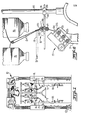
- the spinning machine includes a series of spinning stations. At each spinning station, a supply strand S is directed from a supply package 15 through the strand interrupting apparatus 16. The strand is then directed to the drafting system 17. The strand, upon emergence from the drafting zone has been attenuated into a yarn Y. Twist is then imparted to the yarn Y and it is taken up on a bobbin l8.
- Frames of the type contemplated by the invention are equipped with a traveling unit, generally indicated at 10 which moves along a track 11 extending longitudinally of the spinning frame.
- This unit serves as a "tender", sensing the occurrence of broken yarns and interrupting the corresponding supply strands at such locations, all while simultaneously cleaning the machine and vacuuming lint fibers.
- the typical spinning frame may be conceptualized as mirror image sections when divided along the longitudinal axis.
- the traveling unit 10 is equipped with vacuum units 12, strand detectors 13, and strand interruption actuators 14 which operate on each side of the spinning frame. Further details of the structure and operation of the strand detectors 13 and strand interruption actuators 14 are disclosed in commonly owned U.S. Patent 4,112,665 to Werst and interested readers may refer thereto for a more detailed disclosure of the apparatus.
- the typical spinning machine consists of many individual drafting stations, of which all operate in an essentially identical manner.
- the operation of only one of these drafting stations and its cooperating interrupting apparatus will be discussed in detail.
- each drafting unit is equipped with a strand interrupting apparatus which is the subject matter of the instant application.
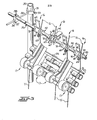
- the embodiment illustrated in Figure 2 depicts the supply strand S passing through the strand interrupting apparatus 16 and then onto the drafting system, generally indicated at 17. More specifically, the drafting system 17 comprises three cooperating sets of rolls, including a set of rear rolls as generally indicated at 21, front or delivery rolls generally indicated at 22, and intermediate rolls 23. As is generally known to persons familiar with textile yarn spinning machines of the type illustrated, the series of rolls 21, 22, 23 define a series of aligned nips through which the supply strand S passes for attenuation. Adjacent the rear rolls 21 is disposed a trumpet 24 which is mounted on traverse bar 25. The trumpet 24 receives the supply strand S and directs the supply strand into the drafting system.
- the strand interruption apparatus 16 When the strand detector 13 ( Figure 1) receives a broken supply strand indication, the strand interruption apparatus 16 is actuated by appropriate means, usually a burst of air. The operation of the strand interruption apparatus appears later in this specification in appropriate detail.
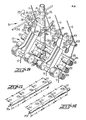
- Figure 3 is illustrative of the means by which the strand interruption apparatus may be easily fitted to any spinning frame currently in use or likely to be marketed in the future.
- strand interruption devices have been mounted directly on the drafting system.
- the design contemplated by this invention is based on the concept of separating the mounting of the strand interruption apparatus from the drafting system, and hence, eliminating the necessity for customizing the apparatus to fit the particular spinning machine involved.
- the strand interruption apparatus includes an elongate strand guide which takes the form of an elongate bar 35. As illustrated, it extends longitudinally of the machine past a plurality of successive drafting units.
- the strand guide 35 is suspended a short distance above the rear of drafting system 17 for engaging and guiding the supply strand S in its course of travel from the supply package 15 to trumpet 24 of the drafting unit.
- a clamp 31 surrounds the spinning frame creel support 32 and is moved into proper position before a cooperating set screw 33 is tightened.
- a support rod 34 is mounted to the clamp 31 by suitable means and serves to support the elongate strand guide means 35.
- the rod 34 passes through a mounting block 36 with a cooperating set screw 37 as well as the elongate strand guide means 35 and cooperating set screw 38, permitting both vertical and horizontal adjustment of the apparatus relative to the spinning machine.
- This arrangement enables the strand interruption apparatus to be properly interposed between the supply package and the drafting system in complete independence of the geometry of the particular machine being fitted.
- the elongate strand guide 35 may be fabricated from metal bar stock or tubing or from other suitable materials, such as plastic.
- the elongate strand guide 35 comprises an elongate, cylindrical solid metal rod of a length sufficient to extend past a plurality of successive drafting units.
- Each elongate strand guide 35 may support a plurality of strand interruption apparatuses.
- the reader will note the versatility of this design in that the spacing of the strand interrupting apparatus on the elongate strand guide may be varied in accordance with the distance between drafting units. Those versed in the art will know that distance between drafting units may vary among the many spinning frame manufacturers.
- a single elongate strand guide 35 may support a plurality of. the strand interruption apparatuses on its outer, or strand1 1 engaging surface, and may extend past a plurality of successive drafting units.
- an abutment member 50 is carried by the elongate strand guide and is correspondingly positioned for cooperating with the respective supply strand S.
- the abutment member 50 may take the form of a sleeve, mounted in surrounding relation on the elongate strand guide 35. This sleeve is essentially cylindrical and has side walls extending generally perpendicular to the longitudinal axis of the elongate strand guide. Included in sleeve 50 is a strand engaging surface 51 which in the illustrated embodiment takes the form of a longitudinally offset projection or anvil, extending along a portion of the inner vertical wall of the sleeve.
- Each sleeve also includes means for fixing its position on the elongate strand guide.
- This means takes the form of a hole extending from the curved outer surface of the sleeve, radially inwardly toward the underlying surface of the elongate strand guide and a cooperating set screw 52.
- the sleeve is surroundingly placed on the elongate strand guide and moved into a position immediately adjacent the supply strand S; then the set screw 52 is engaged to fix the sleeve's position on the elongate strand guide.
- the strand interruption apparatus further comprises a rotatably mounted collar means 60 which is carried by the elongate strand guide and is correspondingly positioned for cooperating with the previously described abutment member 50.
- the collar means takes the form of a cylndrical collar which is surroundingly positioned on the strand guide and is free to rotate about the axis of the strand guide and to move along its longitudinal axis.
- the end of the cylindrical collar located closest to the abutment member 50 defines a strand engaging surface 61 extending generally perpendicular to the axis of the elongate strand guide.
- the collar means is positioned adjacent the abutment member 50, at a distance sufficiently remote to allow the supply strand S to pass freely between the strand engaging surface 51 located on the abutment member 50 and the strand engaging surface 61 on the collar means.
- the collar means 60 also includes a target 62, flag 63, and an offset projection 64.
- the target 62 is mounted longitudinally across the collar and extends vertically upward therefrom.
- Mounted at the end of the target farthest from the collar is a weight 65 which assists the collar in rotating to effect strand interruption.
- the flag 63 or other type of indicator means is attached to the underside of the collar means diametrically opposite the target 62. The flag serves to indicate, by moving into a more easily visible position during strand interruption, which drafting station is in an ends down state.
- a "V" shaped projection 64 extends outwardly from the end of the collar means located opposite the strand engaging surface 6l.
- a pair of cooperating cam surfaces 66, 71 extending helically of the axis of the elongate strand guide 35 is also provided.
- One of the cam surfaces 71 is provided on a second tubular sleeve 70, and the other of the cam surfaces 66 is provided at the end wall of the collar means 60 located opposite the strand engaging surface 61 of the collar means.
- the cam surfaces 66, 71 serve to define means cooperating with the actuator means for moving the collar means 60 along the longitudinal axis of the elongate strand guide 35.
- the second tubular sleeve 70 further comprises a "V" shaped notch 72 in the cam surface thereof which is sized to receive cooperating "V" shaped projection 64 provided on collar 60 during strand feeding and to provide support to the collar means 60 while in the strand feeding position.
- the angular, arrangement of the cooperating projection 64 and notch also serve to prevent the collar 60 from moving laterally due to vibration during operation of the spinning frame, and thereby avoids unintentional contact with the strands on the collar 60.
- supply strand S travels freely between the strand engaging surfaces of the apparatus, namely, between the inside of projection 51 on abutment member 50 and the oppositely located surface 61 of collar 60.
- the attenuated strand emerges from the drafting zone in the form of yarn Y and is wound upon a spindle.
- This operational state known as "strand feeding” is shown in Figures 4, 6, and by the solid lines in Figure 8.
- the strand engaging surfaces 51, 61 are spaced apart and the supply strand S is permitted to run freely therebetween by passing over elongate strand guide 35.
- flag 63 or other indicator means upon actuation of the strand interruption apparatus, moves from the position indicated by the solid lines in Figure 2 to the position indicated by the dotted lines in that same figure.
- This out of line position (best illustrated in Figure 3) enables the spinner to easily locate which drafting system is in an "ends down” state and is in need of "piece-up".
- FIG. 9 The embodiment illustrated in Figure 9 is similar in many respects to that previously illustrated and described in detail. To avoid repetition, elements of this embodiment which correspond to those previously described will be identified by corresponding reference numbers, with prime notation (') added. Basically, this embodiment differs over the previous embodiment in that the cooperating strand engaging surfaces 51' and 61' are toothed or serrated so as to more securely engage and hold the strand S upon actuation and movement of collar 60' axially into the strand engaging position. This is especially suitable for rovings made of very long staple fibers.
- Figure 10 illustrates plurality of the strand interruption apparatusues arranged along the elongate strand guide that--A include this modification.
- Figures 11 and 12 illustrate the modified elongate strand guide 35.
- the strand guide may be fabricated out of metal, such as bar stock or metal tubing, or from other suitable materials, such as plastic.
- the elongate strand guides shown include slots 40a ( Figure 11), or hollows 40b ( Figure 12), through which the strand S flows during normal operation.
- the strand engaging surface of the elongate strand guide could also be formed via other suitable means, such as a bore through the strand guide.
- Such slots or hollows will be spaced at intervals A along the length of the longitudinal axis of the strand guide, generally corresponding to the spacing of the drafting units.
- Figures 13-34 illustrate several embodiments of the strand interrupting apparatus which include the elongate strand guides illustrated in Figures 11 and 12.
- the strand interruption apparatus shown in Figures 13-16 consists of a collar 152 mounted for rotation about the elongate strand guide means 35.
- the collar includes a target 150, flag 154, and an arcoid slot 156 of depth equal to the collar thickness.
- Located in the aforementioned slot is a pin 157, suitably attached to the elongate strand guide and which serves to position the collar 152 and limit its arc of rotation about the elongate strand guide between the strand feeding and strand interrupting positions.
- Located substantially opposite said slot is a projection 153 extending parallel to and radially offset from the axis of rotation of the collar means of thickness equal to that of the collar and of width approximating one half that of the collar.
- supply strand S travels freely between the strand engaging surfaces of the apparatus, in this embodiment, namely the underside of projection 153 (or a portion thereof) and the portion of the outer surface of the elongate strand guide 35 that intersects the outer edge of hollow 40.
- the attenuated strand emerges from the drafting zone and is wound upon a spindle.
- an actuating signal B in the form of a burst of compressed air is directed toward target 150 and the force thereof in cooperation with weight 151 causes clockwise rotation of the collar about the elongate strand guide from the position indicated by the solid lines to the position shown by the dotted lines in Figure 13 and generally shown in Figure 15.
- collar 152 rotates about the elongate strand guide as defined by arcoid slot 156 and limited by pin 157.
- the collar upon rotation, travels longitudinally along the axis of the elongate strand guide in the path defined by the arcoid slot and cooperating pin so as to locate the longitudinal projection to overlie said feed strand and pinch it between the strand engaging surfaces, causing interruption of the supply strand.
- the supply strand S passes outwardly of the elongate strand guide.
- the target 150a is attached via suitable means to the underside of the collar 152a, while the flag 154a and weight 151a are suitably attached opposite said target 150a.
- Actuating means in the form of a burst of air B is directed toward target 150a which causes counterclockwise rotation of the collar about the elongate strand guide 35a. This rotation brings the projection 153a into proximate relation with the strand engaging surface of the strand guide so as to thereby pinch supply strand S.
- the flag is moved out of line into the lowered position indicated by the dotted lines in Figure 18 to aid the spinner in locating a drafting system in the ends down state.
- Figures 22 through 26 illustrate a fourth embodiment of the invention.
- the collar 152b includes two longitudinal projections, one of thickness equal to the thickness of the collar and of length approximately one half the collar width, and a second projection having thickness approximately equal to one half the collar thickness and of length approximately one half the collar width (best shown in Figure 26). These projections are separated by approximately 1 20 degrees along the collar circumference.
- the target 150b is suitably attached at a point on the collar's outer surface approximately equidistant between the two lateral projections.
- the flag 154b and weight 151b are located on the outer surface of the collar substantially opposite the target.
- the elongate strand guide consists of a round bar 35b including a suitably located longitudinally extending projection carried by the outer surface of the bars slightly less than one half the collar thickness, hereinafter termed an "anvil" 162b.
- This anvil acts as one of the strand engaging surfaces during interruption and serves along with pin 157b to longitudinally locate the collar 152b.
- the anvil cooperates with the two lateral projections 160b, 161b to limit the arc of rotation of the collar about the elongate strand guide.
- the collar 152b is mounted for operation such that the anvil 162b is located between the two lateral projections thereby defining its rotational path about the bar of approximately 120 degrees.
- the collar 152b is located longitudinally between the anvil 162b and the pin 157b.
- the supply strand moves along a path defined by the thin longitudinal projection 161b and the anvil 162b (see Figures 22 and 24).
- the burst of air B is directed towards target 150b, which causes the collar 152b to rotate about said bar 35b to the position shown in Figures 23 and 25, thereby causing the strand to be pinched between the anvil 162b and the thinner longitudinal projection 161b thereby causing the supply strand S to break.
- FIGS 27-29 depict a fifth embodiment of the invention which is quite similar to the embodiment previously described except that a sleeve 170c has been added which surrounds the elongate strand guide 35c.
- the strand engaging surface is now located on the outer surface of sleeve 170c, rather than elongate strand guide 35c.
- the outer surface of sleeve 170c carries the anvil 162c and the locating pin 157c.
- the operation of this embodiment is essentially identical to the form of the invention illustrated in Figures 22-26.
- the pin 157c serves the dual functions of restricting the lateral movement of the collar and also serves to locate the entire strand interrupting apparatus along the longitudinal axis of the bar.
- the sleeve enables the strand interruption apparatus to be easily fitted, as the bar serves only a support function and does not act as a strand interrupting surface.
- FIGs 30-32 illustrate a sixth embodiment of the invention which includes a flat cross-sectional bar which serves as the elongate strand guide.
- This flat bar 46 includes stamped grooves which form a depression 46d on one side of said bar and a corresponding projection 47d on the opposite side spaced at distances appropriate for the spinning frame being fitted with the strand interrupting apparatus. These depressions serve as one of the strand engaging surfaces and collar 152d is mounted so as to position the single longitudinal projection 153d to overlie the groove 46d.
- the collar 152d includes a linear slot 156d in which a pin 157d is located, said pin serving the dual purpose of fixing the lateral position of the collar 152d and defining its rotational path.
- a seventh embodiment of the invention is illustrated in Figures 33-34.
- the operation is identical to the embodiment described in detail in Figures 17-21, the major difference being that the entire collar 152e, flag 154e and target 150e structure is one piece, and thus susceptible to mass production via a molding process.
- the collar is made of a material of sufficient flexibility to allow it to be flexed so that it snaps onto the elongate strand guide.
- the collar is slightly larger than semicircular, covering approximately 220 degrees of the outer surface of the bar, small enough to be clipped on, yet of sufficient circumference to enable the collar to be held in place on the elongate strand guide.
- this invention provides an apparatus to facilitate supply strand interruption to be used in conjunction with a spinning frame fitted with a traveling unit which senses a broken supply strand and supplies appropriate means to the strand interrupting apparatus to accomplish supply strand interruption.
- All of the previously described embodiments operate on the basic principle that during normal operation the supply strand is permitted to pass freely between a cooperating pair of strand engaging surfaces, and when strand interruption is required, the collar rotates (in response to an appropriate actuating signal) to move the strand engaging surfaces into proximate relation to cause pinching of the supply strand and to thereby effect strand interruption.
Landscapes
- Engineering & Computer Science (AREA)
- Mechanical Engineering (AREA)
- Textile Engineering (AREA)
- Spinning Or Twisting Of Yarns (AREA)
Applications Claiming Priority (4)
| Application Number | Priority Date | Filing Date | Title |
|---|---|---|---|
| US587396 | 1984-03-08 | ||
| US06/587,396 US4506498A (en) | 1984-03-08 | 1984-03-08 | Textile yarn spinning machine with supply strand interruption |
| US671170 | 1984-11-13 | ||
| US06/671,170 US4581881A (en) | 1984-03-08 | 1984-11-13 | Textile yarn spinning machine with improved supply strand interruption means |
Publications (1)
| Publication Number | Publication Date |
|---|---|
| EP0156452A1 true EP0156452A1 (fr) | 1985-10-02 |
Family
ID=27080015
Family Applications (1)
| Application Number | Title | Priority Date | Filing Date |
|---|---|---|---|
| EP85300058A Withdrawn EP0156452A1 (fr) | 1984-03-08 | 1985-01-04 | Machine de filature avec dispositif d'nterruption de l'alimentation en matière |
Country Status (4)
| Country | Link |
|---|---|
| US (1) | US4581881A (fr) |
| EP (1) | EP0156452A1 (fr) |
| BR (1) | BR8500045A (fr) |
| ES (1) | ES539758A0 (fr) |
Families Citing this family (7)
| Publication number | Priority date | Publication date | Assignee | Title |
|---|---|---|---|---|
| DE3610827A1 (de) * | 1985-12-20 | 1987-06-25 | Zinser Textilmaschinen Gmbh | Spinn-zwirn-maschine |
| CH670663A5 (fr) * | 1986-01-22 | 1989-06-30 | Tashkent Sp K B Textil Mash | |
| DE3744207A1 (de) * | 1987-12-24 | 1989-07-06 | Rieter Ag Maschf | Spinnmaschine mit einer vielzahl von spinnstellen |
| US5339614A (en) * | 1991-07-11 | 1994-08-23 | Maschinenfabrik Rieter Ag | Rotating disc for separating and processing the end of yarn |
| US5566539A (en) * | 1990-07-20 | 1996-10-22 | Binder; Rolf | Method and apparatus for repairing a yarn breakage in a pair of spinning units |
| DE4201575A1 (de) * | 1992-01-22 | 1993-07-29 | Fritz Stahlecker | Spinnmaschine mit jeweils ein streckwerk enthaltenden spinnstellen |
| USD879845S1 (en) * | 2018-05-04 | 2020-03-31 | Uster Technologies Ag | Stopping device for roving on a yarn-spinning machine |
Citations (4)
| Publication number | Priority date | Publication date | Assignee | Title |
|---|---|---|---|---|
| US3638412A (en) * | 1970-05-01 | 1972-02-01 | Leesona Corp | Textile machine |
| US3726072A (en) * | 1971-11-23 | 1973-04-10 | Parks Cramer Co | Apparatus and method for interrupting textile yarn forming operations |
| US3841076A (en) * | 1971-11-23 | 1974-10-15 | Parks Cramer Co | Roving feed stop device |
| EP0016940A1 (fr) * | 1979-03-27 | 1980-10-15 | Maschinenfabrik Rieter Ag | Dispositif mobile de surveillance pour le contrôle successif des conditions de travail de chaque unité de filature d'un métier à filer à anneau |
Family Cites Families (8)
| Publication number | Priority date | Publication date | Assignee | Title |
|---|---|---|---|---|
| US3523413A (en) * | 1968-02-19 | 1970-08-11 | Parks Cramer Co | Apparatus and method for detecting and reporting ends down on textile machines |
| US3659409A (en) * | 1969-10-14 | 1972-05-02 | Parks Cramer Co | Electric circuit means for textile strand ends down detecting apparatus |
| US3832839A (en) * | 1973-10-24 | 1974-09-03 | Parks Cramer Co | Textile yarn spinning machine with roving interruption apparatus and slotted guides |
| US4000603A (en) * | 1975-02-27 | 1977-01-04 | Parks-Cramer Company | Textile yarn spinning machine with supply strand interruption |
| US4112665A (en) * | 1977-06-23 | 1978-09-12 | Parks-Cramer Company | Plural sensor ends down detecting apparatus |
| US4263776A (en) * | 1979-09-24 | 1981-04-28 | Parks-Cramer Company | Apparatus and method for interrupting textile yarn processing operations |
| US4326371A (en) * | 1980-03-03 | 1982-04-27 | Parks-Cramer Company | Supply strand interruption mechanism for textile yarn spinning machine |
| US4506498A (en) * | 1984-03-08 | 1985-03-26 | Parks-Cramer Company | Textile yarn spinning machine with supply strand interruption |
-
1984
- 1984-11-13 US US06/671,170 patent/US4581881A/en not_active Expired - Fee Related
-
1985
- 1985-01-04 EP EP85300058A patent/EP0156452A1/fr not_active Withdrawn
- 1985-01-07 ES ES539758A patent/ES539758A0/es active Granted
- 1985-01-07 BR BR8500045A patent/BR8500045A/pt unknown
Patent Citations (5)
| Publication number | Priority date | Publication date | Assignee | Title |
|---|---|---|---|---|
| US3638412A (en) * | 1970-05-01 | 1972-02-01 | Leesona Corp | Textile machine |
| US3726072A (en) * | 1971-11-23 | 1973-04-10 | Parks Cramer Co | Apparatus and method for interrupting textile yarn forming operations |
| FR2160960A1 (fr) * | 1971-11-23 | 1973-07-06 | Parks Cramer Co | |
| US3841076A (en) * | 1971-11-23 | 1974-10-15 | Parks Cramer Co | Roving feed stop device |
| EP0016940A1 (fr) * | 1979-03-27 | 1980-10-15 | Maschinenfabrik Rieter Ag | Dispositif mobile de surveillance pour le contrôle successif des conditions de travail de chaque unité de filature d'un métier à filer à anneau |
Also Published As
| Publication number | Publication date |
|---|---|
| BR8500045A (pt) | 1985-10-29 |
| ES8601346A1 (es) | 1985-11-16 |
| ES539758A0 (es) | 1985-11-16 |
| US4581881A (en) | 1986-04-15 |
Similar Documents
| Publication | Publication Date | Title |
|---|---|---|
| EP1460015B1 (fr) | Bobinoir pour fil | |
| US5037036A (en) | Yarn end finding apparatus | |
| EP0156452A1 (fr) | Machine de filature avec dispositif d'nterruption de l'alimentation en matière | |
| US4311916A (en) | Travelling scanning apparatus for successively scanning the working conditions at each spinning position of a ring spinning machine | |
| CN103569780B (zh) | 驱动状态检测装置、卷绕单元、卷绕机、纺纱单元及纺纱机 | |
| US4723720A (en) | Yarn end finding device | |
| US3438188A (en) | Yarn defect detecting device | |
| GB2083090A (en) | Apparatus for connecting textile threads by splicing by means of compressed air | |
| US4506498A (en) | Textile yarn spinning machine with supply strand interruption | |
| US5494231A (en) | Method and apparatus for finding and feeding a yarn end to be taken up in a textile winder | |
| CN105398880A (zh) | 储纱装置以及具备该储纱装置的纱线卷绕装置 | |
| CN110735200B (zh) | 用于捻线机或直捻机的纱线张力影响机构 | |
| JP2002145527A (ja) | 特に敏感な巻取り材料用の巻取機 | |
| CN114525604B (zh) | 一种具有可调节导纱装置的并捻机及其控制方法 | |
| JPH01209279A (ja) | 糸送り装置 | |
| EP2019070A2 (fr) | Ensemble amélioré d'alimentation de fibres à grande vitesse | |
| US4495758A (en) | Apparatus and method for forming a wrapped yarn | |
| US6279213B1 (en) | Device for holding and centering textile yarn tubes | |
| EP1300357B1 (fr) | Bobinoir pour fil textile | |
| JP7513657B2 (ja) | 巻糸装置 | |
| US5485967A (en) | Yarn winding apparatus with manifold assembly movable between blowing and standby positions relative to a pair of bobbin carrying spindles | |
| JPH01209273A (ja) | 延反機 | |
| BE1010239A3 (nl) | Garenmonitor voor automatische kruisspoel- en assembleermachines. | |
| US3445894A (en) | Creel stop motion responsive to sliver weight variances | |
| US2964828A (en) | Yarn defect detector |
Legal Events
| Date | Code | Title | Description |
|---|---|---|---|
| PUAI | Public reference made under article 153(3) epc to a published international application that has entered the european phase |
Free format text: ORIGINAL CODE: 0009012 |
|
| AK | Designated contracting states |
Designated state(s): CH DE FR GB IT LI |
|
| STAA | Information on the status of an ep patent application or granted ep patent |
Free format text: STATUS: THE APPLICATION IS DEEMED TO BE WITHDRAWN |
|
| 18D | Application deemed to be withdrawn |
Effective date: 19860603 |
|
| RIN1 | Information on inventor provided before grant (corrected) |
Inventor name: LAMB, JOSEPH THOMAS |