EP0016940A1 - Dispositif mobile de surveillance pour le contrôle successif des conditions de travail de chaque unité de filature d'un métier à filer à anneau - Google Patents
Dispositif mobile de surveillance pour le contrôle successif des conditions de travail de chaque unité de filature d'un métier à filer à anneau Download PDFInfo
- Publication number
- EP0016940A1 EP0016940A1 EP80100723A EP80100723A EP0016940A1 EP 0016940 A1 EP0016940 A1 EP 0016940A1 EP 80100723 A EP80100723 A EP 80100723A EP 80100723 A EP80100723 A EP 80100723A EP 0016940 A1 EP0016940 A1 EP 0016940A1
- Authority
- EP
- European Patent Office
- Prior art keywords
- thread
- suction nozzle
- sensor
- monitoring device
- fiber
- Prior art date
- Legal status (The legal status is an assumption and is not a legal conclusion. Google has not performed a legal analysis and makes no representation as to the accuracy of the status listed.)
- Granted
Links
Images


Classifications
-
- D—TEXTILES; PAPER
- D01—NATURAL OR MAN-MADE THREADS OR FIBRES; SPINNING
- D01H—SPINNING OR TWISTING
- D01H13/00—Other common constructional features, details or accessories
- D01H13/14—Warning or safety devices, e.g. automatic fault detectors, stop motions ; Monitoring the entanglement of slivers in drafting arrangements
- D01H13/145—Warning or safety devices, e.g. automatic fault detectors, stop motions ; Monitoring the entanglement of slivers in drafting arrangements set on carriages travelling along the machines; Warning or safety devices pulled along the working unit by a band or the like
Definitions
- the present invention relates to a wandering monitoring device for the successive monitoring of the working conditions at each spinning position of a ring spinning machine, both with regard to thread breaks and winding formations on drawing frame rollers, with a yarn sensor which senses the presence of a yarn between the feed rollers of the drawing device and the spindle without contact , a second sensor which, when the thread break is determined, detects the presence of a fiber flow between the delivery rollers of the drafting system and the thread break suction nozzle located directly below the lower delivery roller in its normal working position, the fiber flow being deflected by means of a fiber flow deflection device to determine the fiber flow, and one, missing fiber stream, for the actuation of an actuating device provided at each spinning station of the ring spinning machine interruption feed device.
- a ring spinning machine for the definitive spinning out of the thread consists of a large number of spinning positions, usually more than 400, each of which has a drafting system in which the fiber supply (also known as a sliver) is drawn to the final fineness and then by means of a spindle and ring is spun into a thread while giving rotation and wound.
- a drafting system in which the fiber supply (also known as a sliver) is drawn to the final fineness and then by means of a spindle and ring is spun into a thread while giving rotation and wound.
- the present invention relates to the detection of specific working conditions at the spinning station and to the execution of a specific operating operation, namely the shutdown of the material supply if the risk of winding formation around a feed roller of the drafting system is determined.
- the known wandering device has the disadvantage that it requires a very precise guidance of the device along the ring spinning machine, since the spatial distance between the two mentioned races of the fiber ribbon is very small. Such precise guides, however, require a high level of mechanical effort.
- a wandering monitoring device for an automatic thread-tying device (thread applicator) for ring spinning machines which among other things also contains a device for detecting the fiber rolls on the delivery rolls of the drafting system. It consists of two wheels with axial openings, which are mounted very close to the delivery roller periphery. When a fiber roll builds up, the wheel is set in rotation by contact with the roll, which is visually determined. Instead of optical monitoring, a contact tongue for the lower metallic delivery roller is also proposed.
- the mechanical scanning of the delivery roller also has the disadvantage that it requires a very precise and expensive guidance of the monitoring device along the machine; it is also relatively complicated to set up, which has an adverse effect on its price and reliability.
- a monitoring device of the type mentioned at the outset is known from a non-prepublished Swiss application No. 10164/72, in which a fiber stream deflection device is provided.
- the fiber flow deflection device serves the purpose, in the event of thread breakage and controlled by a yarn sensor, to take up the fiber stream originating from the drafting system and carried along by the suction air flow of the suction system by suction and to feed it to a fiber detector.
- This known monitoring device has the disadvantage that it requires a moving suction source, which makes the device complicated and expensive.
- a monitoring device of the type mentioned at the outset in that the thread breakage suction nozzle can be lowered from its normal working position by the fiber stream deflection device actuated by the monitoring device into a scanning position sufficiently distant for the contactless detection of the fiber stream from the lower delivery roller, and in that the second sensor is off a radiation source, which sends a beam onto the deflected fiber stream, and a radiation receiver, which receives the beam influenced by the deflected fiber stream.
- the monitoring device also solves subtasks c) and d), the further claims 2 to 6 relating to advantageous design variants which are of particular importance with regard to solving subtask d).
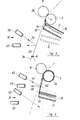
- a roving spool 1 which is rotatably supported in an attachment (not shown) provides a roving 2 for feeding a spinning station.
- the spinning station essentially consists of a drafting unit 3 having a pair of feed rollers 4.5 and a pair of delivery rollers 6.7, a thread eyelet 8 and a ring 9-rotor 10-spindle 11 combination.
- the spindle 11 is rotatably mounted in a spindle bank 12 which extends over the entire length of the ring spinning machine and is shown in FIG Rotation offset.
- the lower rollers 5 and 7 of the drafting system 3 are normally designed as metal cylinders extending over the entire length of the machine, while the upper rollers 4 and 6 mostly take the form of so-called tandem presses pressed against the corresponding lower rollers 5 and 7 by means not shown.
- a thread break suction nozzle 13 At the outlet from the pair of delivery rollers 6, 7 there is a thread break suction nozzle 13 (see also FIG. 1 a), which in FIGS. 1 and 1 a is designed as the mouth 14 of a suction pipe 15.
- the tubular design of the thread break suction shown here known in practice as a single suction, is not the only one which can be considered in the context of this invention; it is also possible to use a flute-like suction tube which is known per se and extends over a plurality of adjacent spinning stations in the longitudinal direction of the spinning machine and has one nozzle per spinning station.
- the suction pipe 15 is connected in an articulated manner to a longitudinal channel 16, which is arranged inside the ring spinning machine and is under vacuum, e.g. by means of a rubber sleeve 17, so that the mouth 14 is displaceable in height.
- the nozzle 13 exerts a suction effect during the entire operating time of the machine.
- the suction pipe 15 carries on its front part a laterally attached extension 18 (Fig. La), which extends beyond the mouth 14 and whose function is described below.
- a roving feed interruption device 19 is provided at each spinning position in front of the feed roller pair 4, 5 in the running direction of the roving 2, which can be actuated from the outside by the traveling monitoring device to be described below, with the purpose of controlling the roving feed to the drafting device 3 in a controlled manner accomplish.
- the roving supply interruption device 19 of the ring spinning machine shown in FIG. 1 consists, for example, of a bore 20 through which the roving 2 is drawn and of a slide 21 by means of which the bore 20 can be closed.
- the slider 21 is connected to an actuating rod 22, by means of which the slider 21 can be actuated from outside the machine.
- other roving supply interruption devices can also be used in the context of this invention (cf. FIGS. 4 to 6).
- the roving 2 is drawn off the roving spool 1 by the rotation of the pair of feed rollers 4, 5.
- the roving 2 is warped as required, so that a thin fiber ribbon (see also FIGS. 2 and 3) leaves the pair of delivery rollers 6, 7, which are twisted in and spun into the finished yarn 23.
- This passes through the thread eyelet 8 and, with the formation of a balloon 24, is wound onto the thread spool 25, which is on the spindle 11 and rotates with it.
- the fiber ribbon 26 (FIG. 2) emerging from the delivery rollers 6, 7, which is no longer spun in, is immediately sucked off and removed from the thread break suction nozzle 13.
- the fiber material sucked off by the thread break suction nozzle 13 is considered inferior waste, so that its amount must be kept as small as possible.
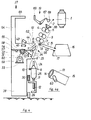
- the monitoring device 27 traveling along the ring spinning machine consists of a supporting structure 28, not shown in more detail, which is in contact with the lower rollers 29 on the floor and with the upper rollers 30 on a longitudinal member of the machine, e.g. supported on the spindle bench 12.
- the upper rollers 30 assume the guiding function in the longitudinal direction of the machine.
- the monitoring device 27 could, however, also be guided in its upper part by the attachment (not shown) of the ring spinning machine, since the type of guidance of the device 27 plays a subordinate role.
- the device 27 is equipped with suitable drive and centering means (both not shown) known per se, by means of which it is driven to move along the machine and can be stopped in a specific operating position in front of each spinning station.
- optical sensor known per se described here can be used as yarn sensor 31, but all known methods (e.g. mechanical buttons, temperature sensors, rotor sensors, etc.) can be used.
- control device 36 which contains the necessary circuits for the functionally appropriate control.
- FIGS. 2 and 3 show the scanning zone of the fiber stream in an enlarged view.
- the thread sensor 31 determines that the yarn 23 is present is; whereupon the monitoring device 27 does not stop at the spinning station, but moves on to the next spinning station.
- FIG. 2 also shows the case when a thread break has occurred at the spinning station, and thus from the clamping line x of the delivery rollers 6, 7 to the thread break suction nozzle 13 lying in the normal working position C, not a yarn 23 but a fiber stream 26 ( flows in the form of a ribbon.
- the thread is attached (manually or automatically, if, for example, the monitoring device 27 itself also carries the means (not shown) for this function, or if another automatic device is provided specifically for this purpose ) nothing stands in the way.
- FIG. 2 the scanning position D, deflected according to the invention, of the thread break suction nozzle 13 is also shown in broken lines, which corresponds to the position of the nozzle 13 shown in FIG. 3.
- FIG. 3 shows the arrangement of FIG. 2 with the thread break suction nozzle 13 lowered, ie if a thread break has occurred at the spinning position (dot-dash line shows the position of the normal-running yarn) and the thread break suction nozzle 13 from the working position C into the position of the thread by the monitoring device 27 according to the invention Scanning position D was lowered.
- An elongated fiber stream 42 is thus formed between the lower delivery roller 7 and the nozzle 13 and is detected by the light beam 44 from the light transmitter 43.
- the light beam 44 that is not reflected in the absence of the fiber stream 42 is shown in dash-dot lines on the extension of the light beam 44, which bumps into the empty space behind the scanning zone, where there is no possibility of influencing, in particular no possibility of reflection, not even through the surface of a roll 54 formed around the lower delivery roller 7.
- the lowering of the thread break suction nozzle 13 and the scanning of the fiber stream with the beam 44 in the lowered state of the nozzle 13 thus create the conditions for optimum operational safety of the monitoring device.
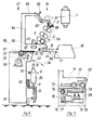
- FIG. 4 to 6 a variant of a monitoring device is shown, namely during different phases of the intervention at a spinning station.
- the same elements as in Fig. 1 are designated by the same reference numerals.
- the fiber flow deflection device here consists of a carriage 55 which is displaceably guided in the transverse direction of travel of the monitoring device 27. This is guided on rollers 56 and can be driven by a motor 59 by means of gear 57 and gear rack 58 which is in engagement therewith, e.g. via a chain drive 60. Control means (not shown) controls the motor 59 such that the carriage 55 can stop at certain points in relation to the supporting structure 28.
- the carriage 55 has a front section 61 facing the spinning positions of the ring spinning machine, in which a guide slot 62 is present.
- the cam 63 engages in this guide slot 62 (see also FIG. 4a), which is fastened on the suction pipe 15 in the vicinity of the mouth 14 of the thread break suction nozzle 13.
- the relative position of the guide slot 62, the elements 43, 45 of the second sensor and the plug 65 must be selected so that they become effective at the correct time or in the correct position during the transverse displacement of the carriage 55 to the spinning position.
- a device known per se with a funnel 66 and a rocker arm 67 is used as the roving feed interruption device 19.
- the rocker arm 67 has at one of its ends a body 68 complementary to the interior of the funnel 66 and at the other end an extension 69.
- the extension 69 assumes such a position that it is pushed by the plug 65 during the transverse displacement of the latter, whereby the rocker arm 67 tilts clockwise and the body 68 closes the funnel 66.
- the roving 2 is clamped between the funnel 66 and the body 68 and thus torn between the funnel 66 and the feed rollers 4, 5, i.e. interrupted.
- FIG. 4 shows a spinning position at which the yarn 23 is spun normally: the presence of a yarn is determined by the yarn sensor 31 and the monitoring device 27 continues to run along the ring spinning machine.
- FIGS. 5 shows the occurrence of a thread break in that the light beam 34 is not reflected by the light transmitter 32, so that a corresponding signal is emitted to the control unit 36 (not shown) via the light receiver 33.
- monitoring device 27 stops, and control device 36 starts motor 59.
- the carriage 55 is shifted towards the spinning station.
- the cam 63 of the thread break suction nozzle 13 engages in the guide slot 62 of the carriage 55.
- the guide slot 62 is inclined backwards and downwards in the direction of displacement of the slide 55 in such a way that the cam 63 swivels downward when the slide 55 is moved further.
- a fiber stream 42 is formed between the delivery rollers 6, 7 and the nozzle 13 pivoted downward. This is provided that a fiber stream is already present on the clamping line x of the rollers 6 and 7 before the thread break suction nozzle 13 is lowered.
- the monitoring device is shown in the position at which the cam 63 of the thread break suction nozzle 13 has reached the lowest point in the guide slot 62, ie at which the nozzle 13 is furthest away from its working position and thus an elongated fiber stream 42 is present.
- This position corresponds to the scanning position D of the thread break suction nozzle 13, in which the motor 59 is switched off by means not shown (for example a switch).
- the light transmitter 43 and the light receiver 45 of the second sensor are also fastened on the slide 55 in a position such that the reflection of the light beam 44 emitted by the light transmitter 43 by the Fiber stream 42, as a reflected light beam 46, to the light receiver 45 takes place in the position of the carriage 55 shown in FIG. 5.
- the light receiver 45 receives a light beam 46; it thus emits a signal to the control unit, not shown, which signals that a thread break has occurred at the spinning position and the non-spun fiber material flows correctly into the thread break suction nozzle 13. This means: there is no winding.
- the control unit will now restart the motor 59 in the opposite direction, i.e. the carriage 55 returns to its rest position shown in FIG. 4, which also brings the thread break suction nozzle 13 back to its normal working position.
- FIG. 6 shows what happens when the light beam 44 with the carriage 55 in the position of FIG. 5 is not reflected by a fiber stream 42, i.e. if (with high probability) the fibers are around a delivery roller, e.g. around the lower delivery roller 7, wind it up as a fiber roll 54, which poses an acute risk of damage to the drafting system 3.
- the light receiver 45 cannot receive a reflected light beam.
- the control is now designed so that the motor 59 is started again, but this time in the same direction as before, i.e. in the sense of a further approach of the carriage 55 to the spinning station.
- the thread breakage suction nozzle 13 is practically no longer displaced from its scanning position, since the guide slot 62 has a section 70 parallel to the direction of movement of the slide 55.
- the roving feed interruption device 19 is actuated by the plug 65, i.e. the feed of the roving 2 to the drafting device 3 is interrupted. This is done in the variant of FIGS.
- FIGS. 4 to 6 has the advantage of simplicity, since all monitoring functions of the monitoring device 27 can only be carried out by the movement of a single organ, namely the carriage 55, with a suitable control device ensuring that the movement of carriage 55 can be carried out in two phases, as explained in detail above.
- FIG. 7 shows a variant of a detail of a monitoring device according to FIG. 4, in which the two-phase movement of the carriage 71, which also has a guide slot 62, instead of being realized by means of a rack and pinion drive by means of a spindle drive.
- the carriage 71 is rigidly connected to a driver 72, which has a threaded bore for a threaded shaft 73 mounted in the supporting structure 28.
- the threaded shaft 73 is connected to a reversible motor 76 by means of a pair of wheels 74, 75.
- the oblique edge 77 of the driver 72 serves at the same time as a switching cam for two switches 78 and 79 which are arranged along the movement path and which are electrically connected to the control device, also not shown, by lines which are not shown.
- the carriage 71 is stopped in the scanning position D described above.
- a fiber stream 42 FIG. 5
- either the motor 76 is reversed and put into operation by the control device, with which the carriage 71 returns to the rest position, or is put into operation again in the same direction, until switch 79 is also actuated.
- the roving feed interruption device 19 is actuated and the motor 76 is reversed, whereby the carriage 71 is brought back into the rest position.
Landscapes
- Engineering & Computer Science (AREA)
- Mechanical Engineering (AREA)
- Textile Engineering (AREA)
- Spinning Or Twisting Of Yarns (AREA)
Applications Claiming Priority (2)
| Application Number | Priority Date | Filing Date | Title |
|---|---|---|---|
| CH282079 | 1979-03-27 | ||
| CH2820/79 | 1979-03-27 |
Publications (2)
| Publication Number | Publication Date |
|---|---|
| EP0016940A1 true EP0016940A1 (fr) | 1980-10-15 |
| EP0016940B1 EP0016940B1 (fr) | 1983-05-18 |
Family
ID=4242316
Family Applications (1)
| Application Number | Title | Priority Date | Filing Date |
|---|---|---|---|
| EP80100723A Expired EP0016940B1 (fr) | 1979-03-27 | 1980-02-13 | Dispositif mobile de surveillance pour le contrôle successif des conditions de travail de chaque unité de filature d'un métier à filer à anneau |
Country Status (6)
| Country | Link |
|---|---|
| US (1) | US4311916A (fr) |
| EP (1) | EP0016940B1 (fr) |
| JP (1) | JPS55128028A (fr) |
| DE (1) | DE3063228D1 (fr) |
| ES (1) | ES490564A0 (fr) |
| IN (1) | IN152642B (fr) |
Cited By (5)
| Publication number | Priority date | Publication date | Assignee | Title |
|---|---|---|---|---|
| DE3042946A1 (de) * | 1980-11-14 | 1982-07-08 | Zinser Textilmaschinen Gmbh, 7333 Ebersbach | Spinnanlage |
| EP0156452A1 (fr) * | 1984-03-08 | 1985-10-02 | Parks-Cramer Company | Machine de filature avec dispositif d'nterruption de l'alimentation en matière |
| DE3524073A1 (de) * | 1985-07-05 | 1987-01-08 | Zinser Textilmaschinen Gmbh | Verfahren und anlage zum beheben von fadenbruechen |
| US5142856A (en) * | 1989-08-10 | 1992-09-01 | Toray Engineering Co., Ltd. | Yarn piecing method for yarn spinning machine |
| EP3748052A1 (fr) | 2019-06-07 | 2020-12-09 | Sanko Tekstil Isletmeleri Sanayi Ve Ticaret Anonim Sirketi | Système à filer à anneaux pour la production d'un fil et procédé d'arrêt de l'alimentation de filaments à un étage d'étirage d'un système à filer à anneaux |
Families Citing this family (10)
| Publication number | Priority date | Publication date | Assignee | Title |
|---|---|---|---|---|
| DE3123476C2 (de) * | 1981-06-13 | 1984-05-17 | Skf Kugellagerfabriken Gmbh, 8720 Schweinfurt | Arbeitsverfahren und Vorrichtung zum Stillsetzen einer Arbeitsstelle einer Spinn- oder Zwirnmaschine |
| US4452168A (en) * | 1981-06-29 | 1984-06-05 | At&T Technologies, Inc. | Apparatus for detecting breaks in strand material |
| DE3331772C2 (de) * | 1983-05-11 | 1985-04-25 | Erwin Sick Gmbh Optik-Elektronik, 7808 Waldkirch | Optische Fadenrißüberwachungsvorrichtung |
| EP0187292B1 (fr) * | 1984-12-31 | 1988-09-21 | Erwin Sick GmbH Optik-Elektronik | Casse-fil optique pour machine à touffeter |
| JPS6290339A (ja) * | 1985-10-14 | 1987-04-24 | Toray Ind Inc | 自動糸継ぎ機 |
| EP0322471B1 (fr) * | 1987-12-24 | 1991-08-28 | Barco Automation, Naamloze Vennootschap | Dispositif pour mesurer un fil |
| US5017797A (en) * | 1988-11-24 | 1991-05-21 | Murata Kikai Kabushiki Kaisha | Device for detecting yarn |
| IT1265050B1 (it) * | 1993-08-06 | 1996-10-28 | Savio Macchine Tessili Srl | Procedimento e dispositivo per controllare l'integrita' e il livello qualitativo di un filato ritorto |
| DE102015005328A1 (de) * | 2015-04-27 | 2016-10-27 | Saurer Germany Gmbh & Co. Kg | Vorrichtung und Verfahren zum Ermitteln des Durchmessers eines durch einen laufenden Faden gebildeten Fadenballons an einer Arbeitsstelle einer Textilmaschine |
| CN112251861B (zh) * | 2020-09-08 | 2022-10-11 | 太原科技大学 | 一种环锭纺细纱机断头检测装置及检测方法 |
Citations (4)
| Publication number | Priority date | Publication date | Assignee | Title |
|---|---|---|---|---|
| GB406063A (en) * | 1932-03-24 | 1934-02-22 | Pierre Swyngedauw | Improvements in suction devices for collecting broken ends in spinning and like machines |
| GB950485A (en) * | 1959-03-05 | 1964-02-26 | Ernst Jacobi | Suction device for textile machinery |
| FR2070857A1 (fr) * | 1969-12-15 | 1971-09-17 | Leesona Corp | |
| FR2390523A1 (fr) * | 1977-05-11 | 1978-12-08 | Rieter Ag Maschf | Procede et dispositif pour la surveillance sequentielle des conditions de fonctionnement d'une machine a filer a anneaux |
Family Cites Families (4)
| Publication number | Priority date | Publication date | Assignee | Title |
|---|---|---|---|---|
| DE2139961A1 (de) * | 1971-08-10 | 1973-03-01 | Braunschweigische Masch Bau | Diffusionsturm |
| DE2533655C2 (de) * | 1974-10-09 | 1986-11-27 | Toray Industries, Inc., Tokio/Tokyo | Spinnmaschine zur Herstellung von gebündeltem Garn |
| DE2714353A1 (de) * | 1977-03-31 | 1978-10-12 | Fritz Stahlecker | Textilmaschine mit vorrichtungen zum erfassen der querdimension des laufenden garns |
| US4186309A (en) * | 1977-10-13 | 1980-01-29 | Web Printing Controls Co. Inc., | Web monitoring and control apparatus for web handling machinery |
-
1980
- 1980-02-13 DE DE8080100723T patent/DE3063228D1/de not_active Expired
- 1980-02-13 EP EP80100723A patent/EP0016940B1/fr not_active Expired
- 1980-02-19 IN IN183/CAL/80A patent/IN152642B/en unknown
- 1980-03-17 US US06/130,822 patent/US4311916A/en not_active Expired - Lifetime
- 1980-03-25 ES ES490564A patent/ES490564A0/es active Granted
- 1980-03-27 JP JP3828580A patent/JPS55128028A/ja active Granted
Patent Citations (4)
| Publication number | Priority date | Publication date | Assignee | Title |
|---|---|---|---|---|
| GB406063A (en) * | 1932-03-24 | 1934-02-22 | Pierre Swyngedauw | Improvements in suction devices for collecting broken ends in spinning and like machines |
| GB950485A (en) * | 1959-03-05 | 1964-02-26 | Ernst Jacobi | Suction device for textile machinery |
| FR2070857A1 (fr) * | 1969-12-15 | 1971-09-17 | Leesona Corp | |
| FR2390523A1 (fr) * | 1977-05-11 | 1978-12-08 | Rieter Ag Maschf | Procede et dispositif pour la surveillance sequentielle des conditions de fonctionnement d'une machine a filer a anneaux |
Cited By (8)
| Publication number | Priority date | Publication date | Assignee | Title |
|---|---|---|---|---|
| DE3042946A1 (de) * | 1980-11-14 | 1982-07-08 | Zinser Textilmaschinen Gmbh, 7333 Ebersbach | Spinnanlage |
| EP0156452A1 (fr) * | 1984-03-08 | 1985-10-02 | Parks-Cramer Company | Machine de filature avec dispositif d'nterruption de l'alimentation en matière |
| DE3524073A1 (de) * | 1985-07-05 | 1987-01-08 | Zinser Textilmaschinen Gmbh | Verfahren und anlage zum beheben von fadenbruechen |
| US5142856A (en) * | 1989-08-10 | 1992-09-01 | Toray Engineering Co., Ltd. | Yarn piecing method for yarn spinning machine |
| EP3748052A1 (fr) | 2019-06-07 | 2020-12-09 | Sanko Tekstil Isletmeleri Sanayi Ve Ticaret Anonim Sirketi | Système à filer à anneaux pour la production d'un fil et procédé d'arrêt de l'alimentation de filaments à un étage d'étirage d'un système à filer à anneaux |
| WO2020244813A1 (fr) | 2019-06-07 | 2020-12-10 | Sanko Tekstil Isletmeleri Sanayi Ve Ticaret Anonim Sirketi | Système de filature à anneaux pour produire un fil et procédé pour arrêter l'alimentation en filaments à un étage d'étirage d'un système de filature à anneaux |
| EP3748052B1 (fr) | 2019-06-07 | 2023-06-07 | Sanko Tekstil Isletmeleri Sanayi Ve Ticaret Anonim Sirketi | Système à filer à anneaux pour la production d'un fil et procédé d'arrêt de l'alimentation de filaments à un étage d'étirage d'un système à filer à anneaux |
| US11885048B2 (en) | 2019-06-07 | 2024-01-30 | Sanko Tekstil Isletmeleri Sanayi Ve Ticaret Anonim Sirketi | Ringspinning system for producing a yarn and method for stopping the supply of filaments to a drafting stage of a ringspinning system |
Also Published As
| Publication number | Publication date |
|---|---|
| DE3063228D1 (en) | 1983-07-07 |
| JPH0213049B2 (fr) | 1990-04-03 |
| JPS55128028A (en) | 1980-10-03 |
| US4311916A (en) | 1982-01-19 |
| IN152642B (fr) | 1984-02-25 |
| EP0016940B1 (fr) | 1983-05-18 |
| ES8104451A1 (es) | 1981-04-16 |
| ES490564A0 (es) | 1981-04-16 |
Similar Documents
| Publication | Publication Date | Title |
|---|---|---|
| EP0016940B1 (fr) | Dispositif mobile de surveillance pour le contrôle successif des conditions de travail de chaque unité de filature d'un métier à filer à anneau | |
| EP0296546B1 (fr) | Métier à filer pour la production de fils d'un ruban de fibres discontinues | |
| DE3515765C2 (fr) | ||
| DE69803275T2 (de) | Verfahren zum individuellen fadenanspinnen an einer arbeitseinheit einer rotorspinnmaschine und vorrichtung zur durchführung des verfahrens | |
| DE2648621B2 (de) | Doppeldraht-Zwirnmaschine | |
| EP1071837B1 (fr) | Procede et dispositif de filage avec suppression du ballon de fil | |
| DE2816807C2 (de) | Verfahren und eine Vorrichtung zur sukzessiven Überwachung der Arbeitsbedingungen an mehreren Spinnstellen einer Ringspinnmaschine | |
| DE1905163A1 (de) | Spinnverfahren und Einrichtung zur Durchfuehrung des Verfahrens | |
| DE1510800C3 (de) | Vorrichtung zum selbsttätigen Spulenwechsel an Doppeldrahtzwirnmaschinen | |
| DE3903782C2 (de) | Verfahren zum Anspinnen einer Offenend-Spinnvorrichtung und Offenend-Spinnmaschine mit einer Einrichtung zum Anspinnen einzelner oder mehrerer Spinnvorrichtungen | |
| DE3336040A1 (de) | Ringspinn- oder -zwirnmaschine | |
| DE19915529A1 (de) | Vorrichtung zum Wickeln konischer Spulen bei konstanter Fadenliefergeschwindigkeit | |
| DE3828323A1 (de) | Verfahren und vorrichtung zum aufnehmen eines fadenendes einer spule beim anspinnen | |
| DE3022149A1 (de) | Umwindegarn-spinnaggregat | |
| DE19548232C5 (de) | Verfahren und Vorrichtung zum Trennen eines Faserbandes beim Kannenwechsel an einer Strecke | |
| DE3315034A1 (de) | Verfahren und vorrichtung zum anspinnen an einem spinnaggregat einer oe-friktionsspinnmaschine | |
| CH684836A5 (de) | Verfahren zur Steuerung der Arbeitsabläufe zwischen einem Bedienungsautomaten und einer Spinnstelle einer Textilmaschine. | |
| DE4122810A1 (de) | Verfahren zum trennen der lunten von auf vorspinnmaschinen gefertigten vorgarnspulen | |
| EP0417662B1 (fr) | Procédé pour commencer le cycle de travail d'un chariot de surveillance dans une machine textile | |
| WO1994000626A1 (fr) | Procede et dispositif pour la mise en place automatique d'un fil nouvellement amene pour etre file, a l'extremite existante d'un fil | |
| WO1990011393A2 (fr) | Procede de fonctionnement d'un metier a filer et automate pour realiser ledit procede | |
| DE3912573A1 (de) | Spinnmaschine mit einer vielzahl von spinnaggregaten und einem wartungsgeraet | |
| EP0568665B1 (fr) | Banc d'etirage pour machine a filer en fin, en particulier pour machine a filer a filiere | |
| DE2540261A1 (de) | Anordnung eines fadenwaechters an spinnstellen einer offenend-spinnmaschine | |
| DE4027210A1 (de) | Spinnmaschine mit einer vielzahl von spinnstellen und mit einer vorrichtung zum beheben eines fadenbruches |
Legal Events
| Date | Code | Title | Description |
|---|---|---|---|
| PUAI | Public reference made under article 153(3) epc to a published international application that has entered the european phase |
Free format text: ORIGINAL CODE: 0009012 |
|
| AK | Designated contracting states |
Designated state(s): CH DE FR GB IT |
|
| 17P | Request for examination filed |
Effective date: 19810406 |
|
| ITF | It: translation for a ep patent filed | ||
| GRAA | (expected) grant |
Free format text: ORIGINAL CODE: 0009210 |
|
| AK | Designated contracting states |
Designated state(s): CH DE FR GB IT |
|
| REF | Corresponds to: |
Ref document number: 3063228 Country of ref document: DE Date of ref document: 19830707 |
|
| ET | Fr: translation filed | ||
| PGFP | Annual fee paid to national office [announced via postgrant information from national office to epo] |
Ref country code: FR Payment date: 19840207 Year of fee payment: 5 |
|
| PLBE | No opposition filed within time limit |
Free format text: ORIGINAL CODE: 0009261 |
|
| PLBE | No opposition filed within time limit |
Free format text: ORIGINAL CODE: 0009261 |
|
| STAA | Information on the status of an ep patent application or granted ep patent |
Free format text: STATUS: NO OPPOSITION FILED WITHIN TIME LIMIT |
|
| 26N | No opposition filed | ||
| 26N | No opposition filed | ||
| GBPC | Gb: european patent ceased through non-payment of renewal fee | ||
| PG25 | Lapsed in a contracting state [announced via postgrant information from national office to epo] |
Ref country code: FR Free format text: LAPSE BECAUSE OF NON-PAYMENT OF DUE FEES Effective date: 19861031 |
|
| REG | Reference to a national code |
Ref country code: FR Ref legal event code: ST |
|
| PG25 | Lapsed in a contracting state [announced via postgrant information from national office to epo] |
Ref country code: GB Effective date: 19881118 |
|
| PGFP | Annual fee paid to national office [announced via postgrant information from national office to epo] |
Ref country code: CH Payment date: 19920115 Year of fee payment: 13 |
|
| ITTA | It: last paid annual fee | ||
| PG25 | Lapsed in a contracting state [announced via postgrant information from national office to epo] |
Ref country code: CH Effective date: 19930228 |
|
| REG | Reference to a national code |
Ref country code: CH Ref legal event code: PL |
|
| PGFP | Annual fee paid to national office [announced via postgrant information from national office to epo] |
Ref country code: DE Payment date: 19940112 Year of fee payment: 15 |
|
| PG25 | Lapsed in a contracting state [announced via postgrant information from national office to epo] |
Ref country code: DE Effective date: 19951101 |