EP0156684A1 - Strahlendes Mirkowellenelement und seine Anwendung in einer elektronisch gesteuerten Antenne - Google Patents
Strahlendes Mirkowellenelement und seine Anwendung in einer elektronisch gesteuerten Antenne Download PDFInfo
- Publication number
- EP0156684A1 EP0156684A1 EP85400336A EP85400336A EP0156684A1 EP 0156684 A1 EP0156684 A1 EP 0156684A1 EP 85400336 A EP85400336 A EP 85400336A EP 85400336 A EP85400336 A EP 85400336A EP 0156684 A1 EP0156684 A1 EP 0156684A1
- Authority
- EP
- European Patent Office
- Prior art keywords
- lines
- radiating element
- coaxial
- central conductor
- conductive
- Prior art date
- Legal status (The legal status is an assumption and is not a legal conclusion. Google has not performed a legal analysis and makes no representation as to the accuracy of the status listed.)
- Withdrawn
Links
- 239000004020 conductor Substances 0.000 claims abstract description 36
- 230000005540 biological transmission Effects 0.000 claims description 3
- 239000003989 dielectric material Substances 0.000 claims description 2
- 230000010287 polarization Effects 0.000 description 23
- 238000004519 manufacturing process Methods 0.000 description 5
- 238000003491 array Methods 0.000 description 2
- 230000005855 radiation Effects 0.000 description 2
- 230000006978 adaptation Effects 0.000 description 1
- 238000010586 diagram Methods 0.000 description 1
- 230000008030 elimination Effects 0.000 description 1
- 238000003379 elimination reaction Methods 0.000 description 1
- 230000005284 excitation Effects 0.000 description 1
- 239000002184 metal Substances 0.000 description 1
- 230000003071 parasitic effect Effects 0.000 description 1
- 230000010363 phase shift Effects 0.000 description 1
- 230000007704 transition Effects 0.000 description 1
Images

Classifications
-
- H—ELECTRICITY
- H01—ELECTRIC ELEMENTS
- H01Q—ANTENNAS, i.e. RADIO AERIALS
- H01Q9/00—Electrically-short antennas having dimensions not more than twice the operating wavelength and consisting of conductive active radiating elements
- H01Q9/04—Resonant antennas
- H01Q9/16—Resonant antennas with feed intermediate between the extremities of the antenna, e.g. centre-fed dipole
-
- H—ELECTRICITY
- H01—ELECTRIC ELEMENTS
- H01Q—ANTENNAS, i.e. RADIO AERIALS
- H01Q21/00—Antenna arrays or systems
- H01Q21/24—Combinations of antenna units polarised in different directions for transmitting or receiving circularly and elliptically polarised waves or waves linearly polarised in any direction
Definitions
- the present invention relates to an element radiating electromagnetic waves, which is particularly interesting in that it can radiate with a switchable polarization.
- the invention also relates to its application to the production of a network antenna, linear or two-dimensional, of the electronic scanning antenna type in particular.
- Array antennas with electronic scanning are already known which radiate electromagnetic waves in fixed rectilinear or circular polarization.
- the rate of elimination of these parasitic elements will be all the more important that one can easily act on the polarization, that is to say on the orientation of the plane of polarization in the case of a rectilinear polarization or on the characteristics of the ellipse of polarization in the case of a circular polarization.
- the present invention makes it possible to solve the technical problem posed by the polarization switching of a radiating element, in particular with a view to producing an antenna with electronic scanning.
- the invention relates to a radiating element designed so that the polarization of the electromagnetic wave it emits is switchable.
- a radiating element designed so that the polarization of the electromagnetic wave it emits is switchable.
- Such an element can radiate a wave according to a switchable polarization, which can be rectilinear in a given direction or in another rectilinear direction orthogonal to the previous one, or else circular straight or left with, for each direction of rotation, several possible configurations of the polarization ellipse.
- the subject of the invention is a radiating element comprising two pairs of adjacent coaxial lines two by two, each associated with a conductive strand in electrical contact with the external conductor of each line, each couple comprising two lines arranged symmetrically with respect to to an axis of symmetry passing through the conductive strands of the two lines of the other couple, the two axes of symmetry being orthogonal so that the four strands form two orthogonal dipoles and in that one of the two coaxial lines of each couple is supplied by one end of its central conductor and the other end of which is electrically connected to the central conductor of the other open coaxial line, by an electrical connection line, so that the phase centers of the two dipoles are combined .
- the invention also relates to the application of the radiating element according to the invention to the production of a network antenna and in particular of a network antenna with electronic scanning.
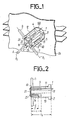
- the radiating element 100 object of the invention comprises two pairs of coaxial lines (1 and 2; 3 and 4) each associated with a conductive strand 5 to 8 respectively.
- the outer conductors of the coaxial lines 1 to 4 are respectively referenced 9 to 12 and their central conductors respectively by 13 to 17.
- Each pair of coaxial lines (1 and 2; 3 and 4) comprises two lines arranged symmetrically with respect to an axis of symmetry, respectively 8 1 and ⁇ 2 , passing through the conductive strands (7 and 8; 5 and 6) of the two lines (3 and 4; 1 and 2) of the other couple, these two axes ⁇ 1 and L 2 being orthogonal.
- the four conductive strands 5 to 8 constitute the radiating strands of two crossed dipoles.
- the strands are excited by the central conductors of the coaxial lines as follows: for each pair of coaxial lines (1 and 2; 3 and 4) one of the lines 1 and 3 is supplied by one of the ends 17 and 18 respectively of its central conductor 13 and 15, the other end of which is electrically connected to the central conductor 14 and 16 of the other coaxial line 2 and 4, which is an open line, by an electrical connection line 21 and 22.
- phase center of each of the two dipoles thus constituted by two coaxial lines (1 and 2; 3 and 4) and by two radiating strands (5 and 6; 7 and 8) is located at the level of the connecting line 21 and 22, equidistant from the central conductors (13 and 14; 15 and 16) of the two lines.
- the phase centers of these two dipoles are therefore confused at point O.
- each pair of coaxial lines (1 and 2; 3 and 4) associated with a dipole consists of two cylinders of conductive material , metal for example, which form the outer conductors of the lines.
- the latter each having two slots 23; 24, for the coaxial line 3 for example, diametrically opposite with respect to the axis of symmetry ⁇ 1 of the dipole formed by the two conductive strands 7 and 8.
- the slots of given length L, allow the excitation of the radiating strands.
- one of the lines has a central conductor of length L equal to the total length of the line and the other line which is an open line has a central conductor of length 1 Less than L.
- connection lines are each constituted for example by a strip of dielectric material, photo-etched on one side, they are arranged perpendicular to one another, the two dielectric faces facing each other to avoid electrical short-circuits.
- connection lines each have two conductive holes 25 at their ends.
- FIG. 3 as in FIG. 1, the radiating element 100 is fixed on a conducting plane 26 playing the role of a reflecting plane.
- Metallic strands 27 placed in front of the radiating strands 5 to 8 are held in place, parallel to each of them, by means of a dielectric support 28 of low dielectric constant, in order to serve as elements directors.
- These guiding elements make it possible to obtain, for each of the dipoles, neighboring radiation diagrams in the site and deposit planes (by increasing the directivity in the plane normal to the axis of the dipoles).
- FIG. 3 represents the preferred embodiment of the radiating element according to the invention.
- the power supply means comprise two energy distributors 29 and 30 produced from two microwave transmission lines of the triplate-air type, according to the subject of the French patent application published under No. 2,496,996. application of such an element to the production of a network antenna, which will be described later, the distributors are each followed by a phase shifter with diodes 31 and 32 of N bits shown in FIG. 5 making it possible to obtain a direction and a determined shape of the antenna beam comprising such a radiating element and of polarizing the wave emitted according to a defined characteristic.
- An output device 51 provides the link between each distributor and the associated phase shifter.
- Each of these phase shifters 31 and 32 is also connected to power distribution means 52. Control, supply and test means 53 are added to these phase shifters.
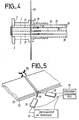
- each of the transmission lines is constituted by two parallel conductive plates 33 and 34 separated from each other by air and elec tricantly at the same potential and by a central conductive tape 35 placed parallel and between the two plates 33 and 34, equidistant from them.
- a radiating element according to the invention it is necessary to use two identical distributors which are superposed.
- one of their ground planes is constituted by a common conductive plate 34.
- each distributor is connected at one end to a diode phase shifter 31 and at another end to the central conductor 13 and 15 of one of the two coaxial lines 1 and 3 of each pair which, associated with the strands conductors 5 and 6 form the radiating element, via a conventional quarter-wave trap 38 and a transition 39 coaxial line - three-plate line also known.
- This trap is produced by the open end of the central conductor of the coaxial lines 1 and 3, which brings a short circuit to ⁇ / 4 from this end.
- the presence of dielectric 50 around the central conductor makes it possible to reduce the mechanical dimensions.
- a radiating element The operation of a radiating element according to the invention is then as follows. Let us consider a couple of coaxial lines 1 and 2 associated with conductive strands 5 and 6 forming a dipole. Part of the energy coming from the phase shifter 31 and flowing in the distributor 29 then in a first coaxial line 1 whose central conductor 13 is connected to the central conductor 35 of the distributor, excites the slots of this coaxial line while another part of this energy, which is transmitted by the connecting line 21 connecting the two coaxial lines 1 and 2, excites the slots of the second open coaxial line 2. All of the currents created by the four slots feed the conductive strands 5 and 6 of the radiating dipole. The two dipoles forming the radiating element are each supplied in the same way so that their two phase centers are merged.
- the wave given by the radiating element will be in polarization linear verti caie for example; if it differs from ⁇ , the polarization will be linear horizontal and if it differs from ⁇ / 2 the polarization will be right or left circular, etc ...
- the invention also relates to the application of the radiating element to the production of a linear antenna, whether linear or two-dimensional, as shown in FIGS. 6 and 7.
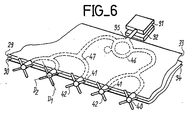
- a linear array antenna shown in perspective in FIG. 6, it is composed of radiating elements 40 according to the invention, aligned at the end of a set of two energy distributors identical 29 and 30 joined to each other as before.
- all the radiating elements 40 have their dipoles inclined in two same orthogonal directions D 1 and D 2 and all the dipoles of the same inclination 41 and 42 respectively are supplied by the same distributor 29 and 30 respectively connected to a N-bit diode shifter 31 e: 32 respectively at its other end.
- each distributor (only that of the distributor 29 has been shown in dotted lines), one end of which is connected to the phase shifter 31 and is connected at its other end to ring dividers 46 followed by branch dividers 7 performing in summer the successive power divisions in order to divide the input power of the distributor to supply each of the radiating elements 40.
- a two-dimensional array antenna with electronic scanning, for example, shown in perspective in FIG. 7, it is constituted by a plurality of linear arrays 45 as they have just been described, all identical and superimposed.
- the distance d separating two linear networks 45 takes account of the operational data, in particular to avoid the appearance of a network lobe, and of the size of the radiating elements 40 relative to each other.
- all dipoles are inclined at only two directions orthogonal tions, D 1 and D 2.
- the polarization of the wave emitted by the antenna is a function of the state of the diodes of the two phase shifters linked to each linear array; as for the particular pointing and beam width characteristics, they depend on the state of the phase shifters.
- the phase shift existing between the states of the two phase shifters of each linear array must be the same for all the linear arrays making up an antenna with electronic scanning.
- the possible number of polarization of the wave emitted by the antenna is linked to the number of bits of the phase shifters - for four-bit phase shifters, there are thirty possible configurations.
- Another advantage comes from the good conservation of the polarization characteristics over part of the beam radiated by the antenna, thanks to the superposition of the phase centers of the two dipoles making up each radiating element.
Landscapes
- Variable-Direction Aerials And Aerial Arrays (AREA)
Applications Claiming Priority (2)
| Application Number | Priority Date | Filing Date | Title |
|---|---|---|---|
| FR8402857A FR2560448B1 (fr) | 1984-02-24 | 1984-02-24 | Element rayonnant des ondes electromagnetiques et son application a une antenne a balayage electronique |
| FR8402857 | 1984-02-24 |
Publications (1)
| Publication Number | Publication Date |
|---|---|
| EP0156684A1 true EP0156684A1 (de) | 1985-10-02 |
Family
ID=9301377
Family Applications (1)
| Application Number | Title | Priority Date | Filing Date |
|---|---|---|---|
| EP85400336A Withdrawn EP0156684A1 (de) | 1984-02-24 | 1985-02-22 | Strahlendes Mirkowellenelement und seine Anwendung in einer elektronisch gesteuerten Antenne |
Country Status (2)
| Country | Link |
|---|---|
| EP (1) | EP0156684A1 (de) |
| FR (1) | FR2560448B1 (de) |
Cited By (4)
| Publication number | Priority date | Publication date | Assignee | Title |
|---|---|---|---|---|
| EP0377921A1 (de) * | 1987-10-10 | 1990-07-18 | THE GENERAL ELECTRIC COMPANY, p.l.c. | Antenne |
| EP0429338A1 (de) * | 1989-11-24 | 1991-05-29 | Thomson-Csf | Zirkular polarisierte Antenne, insbesondere für Gruppenstrahlerantennen |
| US5172128A (en) * | 1989-11-24 | 1992-12-15 | Thomson-Csf | Antenna with circular polarization, notably for antenna array |
| WO2005101575A1 (en) * | 2004-04-15 | 2005-10-27 | Cellmax Technologies Ab | Dipole design |
Citations (7)
| Publication number | Priority date | Publication date | Assignee | Title |
|---|---|---|---|---|
| FR942896A (fr) * | 1943-03-05 | 1949-02-21 | Thomson Houston Comp Francaise | Perfectionnements relatifs aux antennes dipôles pour ondes ultra-courtes |
| DE1101536B (de) * | 1959-10-23 | 1961-03-09 | Siemens Ag | Rohrfoermiger Strahler, insbesondere Ganzwellendipol fuer Antennen des Meter- und Dezimeterwellenbereiches |
| FR1327622A (fr) * | 1962-07-03 | 1963-05-17 | Co El Spa | Dispositif illuminateur à polarisation croisée pour radiocommunications |
| FR2046880A1 (de) * | 1969-06-18 | 1971-03-12 | Kathrein Werke Anton | |
| FR2347792A1 (fr) * | 1976-04-05 | 1977-11-04 | Us Navy | Dispositif de commutation de mode de polarisation |
| US4109254A (en) * | 1975-06-17 | 1978-08-22 | The Marconi Company Ltd. | Dipole radiators for feeding a parabolic reflector |
| FR2439483A1 (fr) * | 1978-10-17 | 1980-05-16 | Nasa | Ensemble d'antenne coaxiale, notamment pour engins spatiaux |
-
1984
- 1984-02-24 FR FR8402857A patent/FR2560448B1/fr not_active Expired
-
1985
- 1985-02-22 EP EP85400336A patent/EP0156684A1/de not_active Withdrawn
Patent Citations (7)
| Publication number | Priority date | Publication date | Assignee | Title |
|---|---|---|---|---|
| FR942896A (fr) * | 1943-03-05 | 1949-02-21 | Thomson Houston Comp Francaise | Perfectionnements relatifs aux antennes dipôles pour ondes ultra-courtes |
| DE1101536B (de) * | 1959-10-23 | 1961-03-09 | Siemens Ag | Rohrfoermiger Strahler, insbesondere Ganzwellendipol fuer Antennen des Meter- und Dezimeterwellenbereiches |
| FR1327622A (fr) * | 1962-07-03 | 1963-05-17 | Co El Spa | Dispositif illuminateur à polarisation croisée pour radiocommunications |
| FR2046880A1 (de) * | 1969-06-18 | 1971-03-12 | Kathrein Werke Anton | |
| US4109254A (en) * | 1975-06-17 | 1978-08-22 | The Marconi Company Ltd. | Dipole radiators for feeding a parabolic reflector |
| FR2347792A1 (fr) * | 1976-04-05 | 1977-11-04 | Us Navy | Dispositif de commutation de mode de polarisation |
| FR2439483A1 (fr) * | 1978-10-17 | 1980-05-16 | Nasa | Ensemble d'antenne coaxiale, notamment pour engins spatiaux |
Non-Patent Citations (1)
| Title |
|---|
| IEEE TRANSACTIONS ON MICROWAVE THEORY AND TECHNIQUES, vol. MTT-14, no. 3, mars 1966, pages 112-119, New York, US; G. OLTMAN: "The compensated balun" * |
Cited By (6)
| Publication number | Priority date | Publication date | Assignee | Title |
|---|---|---|---|---|
| EP0377921A1 (de) * | 1987-10-10 | 1990-07-18 | THE GENERAL ELECTRIC COMPANY, p.l.c. | Antenne |
| US4983987A (en) * | 1987-10-10 | 1991-01-08 | The General Electric Company, P.L.C. | Antenna |
| EP0429338A1 (de) * | 1989-11-24 | 1991-05-29 | Thomson-Csf | Zirkular polarisierte Antenne, insbesondere für Gruppenstrahlerantennen |
| FR2655201A1 (fr) * | 1989-11-24 | 1991-05-31 | Thomson Csf | Antenne a polarisation circulaire, notamment pour reseau d'antennes. |
| US5172128A (en) * | 1989-11-24 | 1992-12-15 | Thomson-Csf | Antenna with circular polarization, notably for antenna array |
| WO2005101575A1 (en) * | 2004-04-15 | 2005-10-27 | Cellmax Technologies Ab | Dipole design |
Also Published As
| Publication number | Publication date |
|---|---|
| FR2560448B1 (fr) | 1987-11-20 |
| FR2560448A1 (fr) | 1985-08-30 |
Similar Documents
| Publication | Publication Date | Title |
|---|---|---|
| EP0205212B1 (de) | Modulare Mikrowellenantenneneinheiten und Antenne mit solchen Einheiten | |
| CA1290449C (fr) | Dispositif d'excitation d'un guide d'onde en polarisation circulaire par une antenne plane | |
| EP0145597B1 (de) | Ebene periodische Antenne | |
| FR2584872A1 (fr) | Antenne plate a large bande a polarisation circulaire, utilisations d'une telle antenne, applications, et procede de fabrication | |
| EP2625741B1 (de) | Grossflächige breitband-oberflächenwellenantenne | |
| FR2505097A1 (fr) | Element rayonnant ou recepteur de signaux hyperfrequences a polarisations circulaires et antenne plane hyperfrequence comprenant un reseau de tels elements | |
| EP0667984A1 (de) | Monopolantenne mit platten- und stabstrahlern | |
| FR2645353A1 (fr) | Antenne plane | |
| FR2766626A1 (fr) | Systeme d'antennes directionnelles a polarisation croisee | |
| CA2029378A1 (fr) | Antenne a polarisation circulaire, notamment pour reseau d'antennes | |
| WO2004001900A1 (fr) | Antenne a brins a polarisation circulaire | |
| FR2646967A1 (fr) | Antenne plane | |
| WO2017025675A1 (fr) | Antenne à ondes de surface, réseau d'antennes et utilisation d'une antenne ou d'un réseau d'antennes | |
| EP0477102B1 (de) | Richtnetzwerk mit benachbarten Strahlerelementen für Funkübertragungssystem und Einheit mit einem derartigen Richtnetzwerk | |
| FR2595511A1 (fr) | Antenne a microbandes et procede pour reduire l'energie residuelle reflechie dans les reseaux d'une telle antenne | |
| WO1991018428A1 (fr) | Antenne orientable plane, fonctionnant en micro-ondes | |
| FR2560448A1 (fr) | Element rayonnant des ondes electromagnetiques et son application a une antenne a balayage electronique | |
| EP2432072B1 (de) | Breitband-Symmetrieüberträger auf mehrlagigem Schaltkreis für eine Netzantenne | |
| EP0065467A1 (de) | Mikrowellenantenne für Zirkularpolarisation | |
| EP1157444A1 (de) | Antenne mit doppelbandiger elektronischerabtastung mit aktivem mirkowellenrefkelektor | |
| FR2677493A1 (fr) | Reseau d'elements rayonnants a topologie autocomplementaire, et antenne utilisant un tel reseau. | |
| EP0088681B1 (de) | Doppelreflektorantenne mit eingebautem Polarisationswandler | |
| EP0831550B1 (de) | Vielseitige Gruppenantenne | |
| FR2689320A1 (fr) | Antenne dalle à balayage électronique et à fonctionnement en bipolarisation. | |
| FR2655201A1 (fr) | Antenne a polarisation circulaire, notamment pour reseau d'antennes. |
Legal Events
| Date | Code | Title | Description |
|---|---|---|---|
| PUAI | Public reference made under article 153(3) epc to a published international application that has entered the european phase |
Free format text: ORIGINAL CODE: 0009012 |
|
| AK | Designated contracting states |
Designated state(s): DE GB IT NL |
|
| 17P | Request for examination filed |
Effective date: 19860322 |
|
| 17Q | First examination report despatched |
Effective date: 19871202 |
|
| RAP3 | Party data changed (applicant data changed or rights of an application transferred) |
Owner name: THOMSON-CSF |
|
| STAA | Information on the status of an ep patent application or granted ep patent |
Free format text: STATUS: THE APPLICATION IS DEEMED TO BE WITHDRAWN |
|
| 18D | Application deemed to be withdrawn |
Effective date: 19890206 |
|
| RIN1 | Information on inventor provided before grant (corrected) |
Inventor name: COHEN, GEORGES |