EP0156720A1 - Verfahren und Vorrichtung zum seitlichen Lochen metallischer Werkstücke, insbesondere Tiefziehteile - Google Patents
Verfahren und Vorrichtung zum seitlichen Lochen metallischer Werkstücke, insbesondere Tiefziehteile Download PDFInfo
- Publication number
- EP0156720A1 EP0156720A1 EP85400460A EP85400460A EP0156720A1 EP 0156720 A1 EP0156720 A1 EP 0156720A1 EP 85400460 A EP85400460 A EP 85400460A EP 85400460 A EP85400460 A EP 85400460A EP 0156720 A1 EP0156720 A1 EP 0156720A1
- Authority
- EP
- European Patent Office
- Prior art keywords
- press
- pattern
- columns
- elementary
- perforations
- Prior art date
- Legal status (The legal status is an assumption and is not a legal conclusion. Google has not performed a legal analysis and makes no representation as to the accuracy of the status listed.)
- Granted
Links
Images

Classifications
-
- B—PERFORMING OPERATIONS; TRANSPORTING
- B21—MECHANICAL METAL-WORKING WITHOUT ESSENTIALLY REMOVING MATERIAL; PUNCHING METAL
- B21D—WORKING OR PROCESSING OF SHEET METAL OR METAL TUBES, RODS OR PROFILES WITHOUT ESSENTIALLY REMOVING MATERIAL; PUNCHING METAL
- B21D28/00—Shaping by press-cutting; Perforating
- B21D28/24—Perforating, i.e. punching holes
- B21D28/28—Perforating, i.e. punching holes in tubes or other hollow bodies
-
- Y—GENERAL TAGGING OF NEW TECHNOLOGICAL DEVELOPMENTS; GENERAL TAGGING OF CROSS-SECTIONAL TECHNOLOGIES SPANNING OVER SEVERAL SECTIONS OF THE IPC; TECHNICAL SUBJECTS COVERED BY FORMER USPC CROSS-REFERENCE ART COLLECTIONS [XRACs] AND DIGESTS
- Y10—TECHNICAL SUBJECTS COVERED BY FORMER USPC
- Y10T—TECHNICAL SUBJECTS COVERED BY FORMER US CLASSIFICATION
- Y10T83/00—Cutting
- Y10T83/384—By tool inside hollow work
- Y10T83/387—Interrelated tool feed means and means to actuate work immobilizer
- Y10T83/388—Actuated clamp element and work holder coact to position work
-
- Y—GENERAL TAGGING OF NEW TECHNOLOGICAL DEVELOPMENTS; GENERAL TAGGING OF CROSS-SECTIONAL TECHNOLOGIES SPANNING OVER SEVERAL SECTIONS OF THE IPC; TECHNICAL SUBJECTS COVERED BY FORMER USPC CROSS-REFERENCE ART COLLECTIONS [XRACs] AND DIGESTS
- Y10—TECHNICAL SUBJECTS COVERED BY FORMER USPC
- Y10T—TECHNICAL SUBJECTS COVERED BY FORMER US CLASSIFICATION
- Y10T83/00—Cutting
- Y10T83/384—By tool inside hollow work
- Y10T83/395—One tool having only rectilinear motion[s]
- Y10T83/40—Multiple external active tools
- Y10T83/401—Tools operate in a substantially common transverse plane of cut
- Y10T83/402—With tool actuating cams on a common support
-
- Y—GENERAL TAGGING OF NEW TECHNOLOGICAL DEVELOPMENTS; GENERAL TAGGING OF CROSS-SECTIONAL TECHNOLOGIES SPANNING OVER SEVERAL SECTIONS OF THE IPC; TECHNICAL SUBJECTS COVERED BY FORMER USPC CROSS-REFERENCE ART COLLECTIONS [XRACs] AND DIGESTS
- Y10—TECHNICAL SUBJECTS COVERED BY FORMER USPC
- Y10T—TECHNICAL SUBJECTS COVERED BY FORMER US CLASSIFICATION
- Y10T83/00—Cutting
- Y10T83/566—Interrelated tool actuating means and means to actuate work immobilizer
- Y10T83/5669—Work clamp
- Y10T83/5787—Clamp driven by yieldable means
- Y10T83/5796—Drive means is resilient
-
- Y—GENERAL TAGGING OF NEW TECHNOLOGICAL DEVELOPMENTS; GENERAL TAGGING OF CROSS-SECTIONAL TECHNOLOGIES SPANNING OVER SEVERAL SECTIONS OF THE IPC; TECHNICAL SUBJECTS COVERED BY FORMER USPC CROSS-REFERENCE ART COLLECTIONS [XRACs] AND DIGESTS
- Y10—TECHNICAL SUBJECTS COVERED BY FORMER USPC
- Y10T—TECHNICAL SUBJECTS COVERED BY FORMER US CLASSIFICATION
- Y10T83/00—Cutting
- Y10T83/869—Means to drive or to guide tool
- Y10T83/8748—Tool displaceable to inactive position [e.g., for work loading]
-
- Y—GENERAL TAGGING OF NEW TECHNOLOGICAL DEVELOPMENTS; GENERAL TAGGING OF CROSS-SECTIONAL TECHNOLOGIES SPANNING OVER SEVERAL SECTIONS OF THE IPC; TECHNICAL SUBJECTS COVERED BY FORMER USPC CROSS-REFERENCE ART COLLECTIONS [XRACs] AND DIGESTS
- Y10—TECHNICAL SUBJECTS COVERED BY FORMER USPC
- Y10T—TECHNICAL SUBJECTS COVERED BY FORMER US CLASSIFICATION
- Y10T83/00—Cutting
- Y10T83/869—Means to drive or to guide tool
- Y10T83/8821—With simple rectilinear reciprocating motion only
- Y10T83/8841—Tool driver movable relative to tool support
-
- Y—GENERAL TAGGING OF NEW TECHNOLOGICAL DEVELOPMENTS; GENERAL TAGGING OF CROSS-SECTIONAL TECHNOLOGIES SPANNING OVER SEVERAL SECTIONS OF THE IPC; TECHNICAL SUBJECTS COVERED BY FORMER USPC CROSS-REFERENCE ART COLLECTIONS [XRACs] AND DIGESTS
- Y10—TECHNICAL SUBJECTS COVERED BY FORMER USPC
- Y10T—TECHNICAL SUBJECTS COVERED BY FORMER US CLASSIFICATION
- Y10T83/00—Cutting
- Y10T83/929—Tool or tool with support
- Y10T83/9411—Cutting couple type
- Y10T83/9423—Punching tool
- Y10T83/944—Multiple punchings
Definitions
- the invention relates to a method and a device for laterally perforating metal parts, in particular stamped parts.
- Such a method makes it possible to open up parts, in particular for a technical or decorative purpose, and more particularly relates to precision openwork in which a large number of immediately adjacent perforations are produced in a room, by punching.
- immediate adjacent perforations is meant perforations such that the distance corresponding to their mutual distance is substantially equal to or less than the width of these perforations.
- French patent n ° 1 048 866 relates to a process for perforating by punching a cylindrical part from an elementary pattern which comprises several perforations spaced from one another and extending along a generatrix of the part: after execution of this pattern, the part is axially shifted to open it again according to this same pattern, by intercalating the perforations made second with those made first; then a slight rotation of the part is carried out to make another series of perforations adjacent to the previous ones, and obtained in the same way.
- one of the aims of the present invention is to provide a method and a device for laterally perforating metal parts of elongated shape with straight generator, in particular cylindrical parts, by means of a large number of conventional punches operating simultaneously.
- Another object of the invention is to provide a method for perforating metal parts, which is automated and of great rapidity of execution.
- a method for perforate an elongated metal part with a straight generator in order to obtain, in several successive passes, a pattern which extends over a large part of the length of the generator and which is constituted by a large number of adjacent perforations in the side wall of this part, this process consisting in repeating at least one elementary pattern which comprises a part of the perforations and which extends over the entire height of the pattern to be produced.
- this elementary pattern is executed in a single pass, two adjacent elementary patterns being executed during different passes.
- pairs of elementary patterns are made at each pass, each consisting of two elementary patterns symmetrical with respect to the axis of the cylindrical part, and a partial rotation of the part is carried out along its axis, between two consecutive passes .
- the elementary patterns are nested circumferentially.
- At least two different elementary patterns are used.
- the invention also relates to a device for implementing this method, which comprises a vertical press; a plurality of columns which extend at least over a substantial part of the length of the generator of the elongated part, and which are mounted to slide horizontally on the press table, along axes converging towards the central axis of the press; means for transforming the downward movement of the mobile part of the press into a simultaneous horizontal displacement of the columns towards the central axis of the press and for ensuring the return of the columns to their initial position when the mobile part rises, these means cooperating with the columns at least in the axially median zone thereof; a plurality of horizontal punches which are carried by the front face of each column facing the center of the press and which are arranged essentially one below the other over the entire height of the column, these punches removing intended to penetrate openings of corresponding section made in a bighorn fixed vertically in the center of the table, this bighorn having a diameter corresponding to the inside diameter of the cylindrical piece to be cut out and being capped by this piece
- each column is provided on its front face with a horizontal sliding stop, compression springs being interposed between the stop and the column, the punches passing through the stop and flush with its front face when the movable part of the press is in high position, and this stopper being progressively pressed against the bighorn when the movable part descends.
- the means for simultaneously operating the columns comprise an arm which is rigidly suspended from the movable part of the press, which cooperates with a recess made in a shoulder of the columns situated in the axially median zone thereof, and which has a part in the form of a ramp, the recess having a corresponding ramp shape, the ramp-shaped part of the arm being extended by a vertical part which cooperates with a recess made in the press table.
- Figure 1 shows the developed side wall 1 of a cylindrical metal piece of elongated shape to be perforated in a pattern which extends over a large part of the length of the generator of this part and over the entire periphery of this part.
- This pattern consists of the juxtaposition of a large number of small areas, the shape of which is chosen from: a large rectangle 2, a large beveled rectangle 3, a small beveled rectangle 4, a small square 5 or a small triangle 6.
- the method according to the invention consists of perforating the wall 1 of the cylindrical part along each of these surfaces.
- the pattern itself which is here a decorative pattern, in a certain way.
- the pattern is obtained by alternately repeating two juxtaposed elementary patterns 7, 8, which extend mainly along two respective generatrices of the cylindrical piece and over the entire height of the pattern to be produced.
- Each elementary pattern 7, 8, consists mainly of an alternation of rectangles 2 and of squares 5 arranged one below the other along these generatrices.
- the two elementary patterns 7, 8, are arranged in a single spacing, around the entire periphery of the cylindrical part and are each repeated eight times, according to this embodiment, each of them being executed in a single pass. It is therefore a question of making a total of sixteen openings in the cylindrical part. It will be noted that the two patterns 7, 8 are nested circumferentially.
- FIG. 2 represents the sixteen angular portions corresponding to the openings to be produced.
- Eight angular portions 71 to 78 relate to the elementary pattern 7
- eight portions 81 to 88 alternating with the previous ones relate to the elementary pattern 8.
- the angular portion 85 underlies the cylinder portion 9 along which the pattern 8 extends.
- the angle between the median planes 10, 11 of two adjacent angular portions always has the same value A.
- the cylindrical part is openwork according to the four arrows 701,702, 801, 802 at each pass, the openings according to the arrows 701, 702 reproducing the elementary pattern 7 and those according to the arrows 801, 802 the elementary pattern 8.
- These four arrows are located in extension of the median plane of four angular portions (71, 72) and (81,82) symmetrical two by two with respect to the axis of the cylindrical part.
- the angle B between the arrows 701 and 801, or 702 and 802 is equal to three times the angle A.
- the angle C ⁇ between the arrows 701 and 802, or 702 and 801 is equal to 5 times the angle A.
- the first pass therefore allows the simultaneous execution of the four openings 71, 72, 81, 82, the angular portions of which are arranged opposite the arrows 701, 702, 801, 802.
- the cylindrical part is then rotated around its axis. in the direction of arrow 12, with an angular value equal to twice the angle A. This has the effect of placing the angular portions (73, 74, 83, 84) respectively in front of the arrows (701, 702, 801 , 802) and make the corresponding cutouts.
- a new rotation of the cylindrical part of the same value allows in the same way to make the openings - (75, 76, 85, 86).
- a final rotation finally allows for the perforations (77, 78, 87, 88).
- the elementary patterns 7, 8 are alternated, and that two adjacent openings are made during passes different.
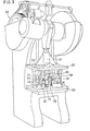
- FIG. 3 as a whole represents a device making it possible to implement the method described above concerning the addition of cylindrical parts. It comprises a vertical press 20 whose slide 21, provided with a sole 22, cooperates with a press table 23. The cylindrical part to be cut out is mounted vertically in the center of the press table 23, on a bighorn 24. Four columns 25 to 28 provided with punches are mounted to slide horizontally on the press table 23 around the bighorn 24. They are set in motion by four arms 29 to 32 suspended from the sole 22 of the press slide 21, when the latter moves vertically.
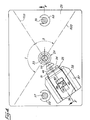
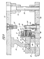
- Figures 4 and 5 show in detail the device of the invention.
- the four columns 25 to 28 are mounted to slide horizontally on the press table 23, along two horizontal axes 700, 800 passing through the vertical central axis 33 of the press.
- the two axes 700, 800 are offset by an angle B, and by a complementary angle C defined in relation to FIG. 2.
- the four columns 25 to 28, their guide means, as well as the arms 29 to 32 are identical . Also, only the characteristics relating to column 25 are shown in FIGS. 4 and 5 and described.
- Column 25 is higher than that of the cylindrical part to be perforated. Its front face 34 is oriented towards the central axis 33 of the press and carries a plurality of punches 47 -of which only a few are shown in Figure 5- extending horizontally towards the axis 33 of the press and arranged one below the others, immediately adjacent, over the entire height of the pattern to be produced.
- the front face 34 of the column 25 also carries horizontal pins 48 making it possible to slide a stopper 50 disposed in front of the front face 34.
- the pins 48 and the punches 47 are pressed on the column 25 by a sole 51.
- the stopper 50 has through channels 52 for the passage of punches 47, and through channels 54 for the passage of pins 48.
- pins 49 limit the sliding of the stopper 50 in the direction of the force exerted by the springs 53; they pass through the column 25 and its sole 51 and are screwed into the stopper 50.
- the pins 49 have an end shoulder 56 which abuts against the column 25 at the end of the front stroke of the stopper 50.
- the front face 55 of the stopper 50 has a curvature corresponding to that of the bighorn 24. At the end of the front stroke of the stopper 50 the punches 47 are flush with its front face 55 by their free end.
- the means for moving and storing the column 25 will now be explained.
- the column 25 is provided with a rear parallelepiped shoulder 35. This extends perpendicular to the column 25, starting from the axially middle zone of the column.
- a parallelepipedal guide 37 is interposed between the shoulder 35 of the column 25 and the press table 23. Its height is such that the column 25 does not rest on the press table 23 but is slightly distant from it.
- the shoulder 35 of the column 25 has two grooves 36 projecting laterally and sliding in corresponding grooves of the guide 37. It is provided with a recess 38 passing through it between its two horizontal faces. This recess 38 has two side walls 39, 40 vertical and two front walls 41, 42 in the form of a ramp inclined towards the press table 23 and radially outward relative to the axis 33 of the press.
- the guide 37 and the press table 23 each have a vertical recess 43, 44 arranged directly above the recess 38.
- the sole 22 of the press slide rigidly carries the hanging arm 29.
- the latter has a shaped part ramp 45 complementary to the recess 38 of the shoulder 35.
- the ramp-shaped part 45 is extended by a vertical part 46 which has, in section, dimensions very slightly; ely smaller than those of the recess 44 of press table 23.
- the arm 29 crosses the shoulder ment 35 of column 25, guide 37 and press table 23, in line with their respective recesses.
- the ramp-shaped part 45 of the arm 29, cooperating with the recess 38 in the shoulder 35, causes the column 25 to move towards the bighorn 24.
- the vertical part 46 of the arm 29 comes lodge in the recess 44 of the press table: the arm 29 is thus rigidly held by its end. It follows that this arm can transmit to the column 25 a significant force, and oppose the reaction force generated by the punching, without buckling. With this arrangement, the number of punches 47, per column, can be large, without the need to size the arm 29, and therefore the entire device, prohibitively.
- the middle position of the shoulder 35 on the column 25 ensures a good distribution of the force on this column.
- the sole of the press slide 22 is positioned in its vertical movement relative to the press table 23 by two alignment pins 57, 58 secured to the press table 23, and sliding in sockets 59, 60 secured to the sole 22 of the press slide.
- the bighorn 24 is of generally cylindrical shape corresponding to that of the part to be perforated, which will come to cap the bighorn 24. In general this bighorn 24 has the same shape as the part to be perforated. It is fixed to the center of the press table 23, and is located opposite the front face 55 of the stopper 50.
- the bighorn 24 is hollow and also has openings 61 in its side wall, the section of which corresponds to that of punches 47, these openings 61 being located exactly opposite the punches 47.
- An automatic chip evacuation device is advantageously connected to the inside of the bighorn 24. On the sole 22, and facing the bighorn 24, is suspended a finger 62 which firmly presses the cylindrical part to be cut out on the bighorn, in the low position of the sole 22, to ensure the precise positioning of the part.
- the cylindrical part is rotated by an angle equal to twice the angle A and in the direction of the arrow 12 in accordance with FIG. 2.
- a second descent of the sole 22 will make it possible to produce the second group of openings (73, 74, 83, 84).
- the perforated cylindrical part is removed from the bighorn and replaced by a non-perforated part.
- each punch can be provided with a detector making it possible to detect a possible break.
- the different detectors are managed by a system IT which indicated every possible breakdown, and which localized it.
- the nesting process of several elementary patterns very advantageously makes it possible to open up the same room area in several stages, so as to stress the wall of the room as little as possible. In the case of extremely dense openwork, a one-pass process is hardly possible. Furthermore, the decomposition of the wall of the room into a large number of portions (71 to 78 and 81 to 88) makes it possible to make an openwork almost perpendicular to this wall; the openings thus have edges perpendicular to this wall. According to the invention, it is possible to perforate not only stamped but also extruded parts.
Landscapes
- Engineering & Computer Science (AREA)
- Mechanical Engineering (AREA)
- Perforating, Stamping-Out Or Severing By Means Other Than Cutting (AREA)
- Shaping Metal By Deep-Drawing, Or The Like (AREA)
- Punching Or Piercing (AREA)
- Forging (AREA)
- Meat, Egg Or Seafood Products (AREA)
- Coating With Molten Metal (AREA)
- Adornments (AREA)
Priority Applications (1)
| Application Number | Priority Date | Filing Date | Title |
|---|---|---|---|
| AT85400460T ATE35636T1 (de) | 1984-03-13 | 1985-03-11 | Verfahren und vorrichtung zum seitlichen lochen metallischer werkstuecke, insbesondere tiefziehteile. |
Applications Claiming Priority (2)
| Application Number | Priority Date | Filing Date | Title |
|---|---|---|---|
| FR8403799A FR2561143B1 (fr) | 1984-03-13 | 1984-03-13 | Procede et dispositif pour ajourer lateralement des pieces metalliques, notamment embouties |
| FR8403799 | 1984-03-13 |
Publications (2)
| Publication Number | Publication Date |
|---|---|
| EP0156720A1 true EP0156720A1 (de) | 1985-10-02 |
| EP0156720B1 EP0156720B1 (de) | 1988-07-13 |
Family
ID=9301950
Family Applications (1)
| Application Number | Title | Priority Date | Filing Date |
|---|---|---|---|
| EP85400460A Expired EP0156720B1 (de) | 1984-03-13 | 1985-03-11 | Verfahren und Vorrichtung zum seitlichen Lochen metallischer Werkstücke, insbesondere Tiefziehteile |
Country Status (8)
| Country | Link |
|---|---|
| US (1) | US4669345A (de) |
| EP (1) | EP0156720B1 (de) |
| JP (1) | JPS617023A (de) |
| AT (1) | ATE35636T1 (de) |
| CA (1) | CA1235370A (de) |
| DE (1) | DE3563700D1 (de) |
| ES (1) | ES8607072A1 (de) |
| FR (1) | FR2561143B1 (de) |
Families Citing this family (5)
| Publication number | Priority date | Publication date | Assignee | Title |
|---|---|---|---|---|
| DE69018082T2 (de) * | 1990-11-09 | 1995-09-28 | Umix Co Ltd | Gesenk mit Führungsschlitten. |
| JP2880490B1 (ja) * | 1997-11-14 | 1999-04-12 | ユミックス株式会社 | プレス装置 |
| CN1296197C (zh) * | 2005-02-01 | 2007-01-24 | 浙江大学 | 丝网、薄片填料冲压机 |
| US20120180911A1 (en) * | 2008-10-03 | 2012-07-19 | Mark Bartolomucci | Method for producing a hole in plate member |
| JP7750637B2 (ja) * | 2023-03-30 | 2025-10-07 | 旭精機工業株式会社 | 穿孔装置及びトランスファプレス機 |
Citations (6)
| Publication number | Priority date | Publication date | Assignee | Title |
|---|---|---|---|---|
| US1398320A (en) * | 1919-09-13 | 1921-11-29 | George W Dunsworth | Pipe-perforator |
| GB249422A (en) * | 1925-06-30 | 1926-03-25 | Joseph Timothy Murphy | Improvements in and relating to punch presses |
| US2315340A (en) * | 1941-08-23 | 1943-03-30 | Midland Steel Prod Co | Punch |
| US2354860A (en) * | 1942-04-23 | 1944-08-01 | Mid West Hydro Pierce Inc | Tube perforating machine |
| FR1048866A (fr) * | 1950-10-16 | 1953-12-24 | Rotovent A G | Procédé pour la fabrication de cribles cylindriques, machine pour la mise en oeuvre du procédé et crible obtenu suivant le procédé |
| GB1172763A (en) * | 1967-04-15 | 1969-12-03 | Nathan Dolberg | Improvements in or relating to Punching Machines. |
Family Cites Families (8)
| Publication number | Priority date | Publication date | Assignee | Title |
|---|---|---|---|---|
| US2325437A (en) * | 1942-07-22 | 1943-07-27 | Victor Metal Products Corp | Hole punching die |
| US2539085A (en) * | 1947-09-02 | 1951-01-23 | Kurt C Kerseg | Die set |
| US2875829A (en) * | 1954-12-01 | 1959-03-03 | Bruno S Patrick | Apparatus for stamping surfaces |
| US3477317A (en) * | 1967-04-12 | 1969-11-11 | Ibm | Method for producing an improved die for use with a multi-element punch |
| US3485124A (en) * | 1967-06-02 | 1969-12-23 | Kentucky Electronics Inc | Automatic machine for making convergence cup electrodes for color television tubes |
| US4036091A (en) * | 1976-06-11 | 1977-07-19 | Alpha Industries, Inc. | Universal double cut die set |
| JPS5530323A (en) * | 1978-08-24 | 1980-03-04 | Aida Eng Ltd | Hydromechanical press |
| JPS56126037A (en) * | 1980-03-05 | 1981-10-02 | Nagumo Seisakusho:Kk | Method and device for piercing to cylindrical body |
-
1984
- 1984-03-13 FR FR8403799A patent/FR2561143B1/fr not_active Expired
-
1985
- 1985-03-08 US US06/709,707 patent/US4669345A/en not_active Expired - Fee Related
- 1985-03-11 JP JP60048078A patent/JPS617023A/ja active Granted
- 1985-03-11 AT AT85400460T patent/ATE35636T1/de not_active IP Right Cessation
- 1985-03-11 EP EP85400460A patent/EP0156720B1/de not_active Expired
- 1985-03-11 CA CA000476239A patent/CA1235370A/en not_active Expired
- 1985-03-11 DE DE8585400460T patent/DE3563700D1/de not_active Expired
- 1985-03-13 ES ES541230A patent/ES8607072A1/es not_active Expired
Patent Citations (6)
| Publication number | Priority date | Publication date | Assignee | Title |
|---|---|---|---|---|
| US1398320A (en) * | 1919-09-13 | 1921-11-29 | George W Dunsworth | Pipe-perforator |
| GB249422A (en) * | 1925-06-30 | 1926-03-25 | Joseph Timothy Murphy | Improvements in and relating to punch presses |
| US2315340A (en) * | 1941-08-23 | 1943-03-30 | Midland Steel Prod Co | Punch |
| US2354860A (en) * | 1942-04-23 | 1944-08-01 | Mid West Hydro Pierce Inc | Tube perforating machine |
| FR1048866A (fr) * | 1950-10-16 | 1953-12-24 | Rotovent A G | Procédé pour la fabrication de cribles cylindriques, machine pour la mise en oeuvre du procédé et crible obtenu suivant le procédé |
| GB1172763A (en) * | 1967-04-15 | 1969-12-03 | Nathan Dolberg | Improvements in or relating to Punching Machines. |
Also Published As
| Publication number | Publication date |
|---|---|
| ES541230A0 (es) | 1986-06-01 |
| FR2561143A1 (fr) | 1985-09-20 |
| CA1235370A (en) | 1988-04-19 |
| FR2561143B1 (fr) | 1987-12-24 |
| US4669345A (en) | 1987-06-02 |
| DE3563700D1 (en) | 1988-08-18 |
| EP0156720B1 (de) | 1988-07-13 |
| JPS617023A (ja) | 1986-01-13 |
| ATE35636T1 (de) | 1988-07-15 |
| ES8607072A1 (es) | 1986-06-01 |
| JPH032568B2 (de) | 1991-01-16 |
Similar Documents
| Publication | Publication Date | Title |
|---|---|---|
| BE1005237A3 (fr) | Procede et appareil pour former des panneaux d'extremites de recipients en une matiere avancee dans une presse. | |
| EP0296024B1 (de) | Verfahren und Einrichtung zur Herstellung von insbesondere metallischen Etiketten mit einer doppelten Codifikation, davon einen Code mit ausgeschnittenen Balken, und derartig hergestellte Etiketten | |
| FR2636044A1 (fr) | Procede et appareil pour former un panneau d'extremite de recipient a partir d'une feuille de matiere | |
| EP0156720B1 (de) | Verfahren und Vorrichtung zum seitlichen Lochen metallischer Werkstücke, insbesondere Tiefziehteile | |
| EP3227068B1 (de) | Transformationsgruppe einer ebenen auflagefläche sowie demontage- und montageverfahren eines drehwerkzeugs in einer transformationsgruppe | |
| WO2008110679A1 (fr) | Machine compacte de conification des boitiers metalliques pour distributeurs aerosols et equivalents | |
| WO1992002059A1 (fr) | Procedes et dispositifs pour sertir mecaniquement une piece de connexion sur un fil | |
| FR2741288A1 (fr) | Outillage reglable de pliage de toles | |
| EP0547954B1 (de) | Rotationsstanzvorrichtung | |
| FR2471936A1 (fr) | Dispositif pour separer un flan d'extremite d'une pile de flans | |
| CA2031859C (fr) | Procede et dispositif d'emboutissage de recipients de forme tronconique, et recipient ainsi embouti | |
| EP0614711B1 (de) | Verfahren und Vorrichtung zum Ziehen von metallischen Rohlingen zur Herstellung sogenannter Tiefziehwerkstücke | |
| EP0031739B1 (de) | Presswerkzeug zum Formen von Statorwicklungen an beiden Seiten eines Stators und mittels dieses Presswerkzeuges erhaltene Statorwicklungen | |
| CH184934A (fr) | Procédé pour la formation d'un bourrelet au bord d'un corps creux obtenu par emboutissage et appareil pour la mise en oeuvre de ce procédé. | |
| EP1320427B1 (de) | Verfahren und anlage zur herstellung eines werkstückes mit zumindest einem rohrförmigen querschnitt | |
| EP0337882B1 (de) | Verfahren und Vorrichtung zur Herstellung von geformten Gemüsen oder Früchten sowie geformte Gemüse oder Früchte, hergestellt nach dem Verfahren | |
| FR2695338A1 (fr) | Procédé pour la réalisation de rangées de piqûres sur une surface d'outil destiné à présenter une fonction de râpe, et outils réalisés. | |
| EP1273365A1 (de) | Rotierendes Stanzwerkzeug zum kontinuierlischen Lochen von Profilen | |
| EP0278870B1 (de) | Vorrichtung für das Serienstempeln von gedruckten Leiterplatten | |
| EP1759782A1 (de) | Vorrichtung und Verfahren zur Bearbeitung von Blechen | |
| FR2612446A1 (fr) | Procede de fabrication d'objets par decoupe de matiere pateuse et dispositif pour la mise en oeuvre de ce procede | |
| FR2497469A1 (fr) | Procede de fabrication d'un tube a ailettes embouti, machine pour sa fabrication, et tube ailete ainsi obtenu | |
| FR2839054A1 (fr) | Dispositif et procede de pliage de sac gonflable pour dispositif de securite de vehicule automobile | |
| FR2742028A1 (fr) | Mecanisme tournant de rouge a levres possedant un nombre reduit de pieces, et procede de fabrication de l'une des pieces de ce mecanisme, a savoir le corps | |
| FR2611544A1 (fr) | Procede de distribution de barres ou tubes allonges et installation pour la mise en oeuvre de ce procede |
Legal Events
| Date | Code | Title | Description |
|---|---|---|---|
| PUAI | Public reference made under article 153(3) epc to a published international application that has entered the european phase |
Free format text: ORIGINAL CODE: 0009012 |
|
| AK | Designated contracting states |
Designated state(s): AT BE CH DE GB IT LI LU NL SE |
|
| 17P | Request for examination filed |
Effective date: 19860318 |
|
| 17Q | First examination report despatched |
Effective date: 19861028 |
|
| GRAA | (expected) grant |
Free format text: ORIGINAL CODE: 0009210 |
|
| AK | Designated contracting states |
Kind code of ref document: B1 Designated state(s): AT BE CH DE GB IT LI LU NL SE |
|
| REF | Corresponds to: |
Ref document number: 35636 Country of ref document: AT Date of ref document: 19880715 Kind code of ref document: T |
|
| REF | Corresponds to: |
Ref document number: 3563700 Country of ref document: DE Date of ref document: 19880818 |
|
| GBT | Gb: translation of ep patent filed (gb section 77(6)(a)/1977) | ||
| ITF | It: translation for a ep patent filed | ||
| PG25 | Lapsed in a contracting state [announced via postgrant information from national office to epo] |
Ref country code: LU Free format text: LAPSE BECAUSE OF NON-PAYMENT OF DUE FEES Effective date: 19890331 |
|
| PLBE | No opposition filed within time limit |
Free format text: ORIGINAL CODE: 0009261 |
|
| STAA | Information on the status of an ep patent application or granted ep patent |
Free format text: STATUS: NO OPPOSITION FILED WITHIN TIME LIMIT |
|
| 26N | No opposition filed | ||
| PGFP | Annual fee paid to national office [announced via postgrant information from national office to epo] |
Ref country code: LU Payment date: 19900214 Year of fee payment: 6 |
|
| PGFP | Annual fee paid to national office [announced via postgrant information from national office to epo] |
Ref country code: BE Payment date: 19900216 Year of fee payment: 6 |
|
| PGFP | Annual fee paid to national office [announced via postgrant information from national office to epo] |
Ref country code: DE Payment date: 19900221 Year of fee payment: 6 |
|
| PGFP | Annual fee paid to national office [announced via postgrant information from national office to epo] |
Ref country code: GB Payment date: 19900228 Year of fee payment: 6 |
|
| PGFP | Annual fee paid to national office [announced via postgrant information from national office to epo] |
Ref country code: SE Payment date: 19900308 Year of fee payment: 6 |
|
| PGFP | Annual fee paid to national office [announced via postgrant information from national office to epo] |
Ref country code: CH Payment date: 19900323 Year of fee payment: 6 |
|
| PGFP | Annual fee paid to national office [announced via postgrant information from national office to epo] |
Ref country code: AT Payment date: 19900327 Year of fee payment: 6 |
|
| ITTA | It: last paid annual fee | ||
| PGFP | Annual fee paid to national office [announced via postgrant information from national office to epo] |
Ref country code: NL Payment date: 19900331 Year of fee payment: 6 |
|
| PG25 | Lapsed in a contracting state [announced via postgrant information from national office to epo] |
Ref country code: GB Effective date: 19910311 Ref country code: AT Effective date: 19910311 |
|
| PG25 | Lapsed in a contracting state [announced via postgrant information from national office to epo] |
Ref country code: SE Effective date: 19910312 |
|
| PG25 | Lapsed in a contracting state [announced via postgrant information from national office to epo] |
Ref country code: LI Effective date: 19910331 Ref country code: CH Effective date: 19910331 Ref country code: BE Effective date: 19910331 |
|
| BERE | Be: lapsed |
Owner name: SUINAT Effective date: 19910331 |
|
| PG25 | Lapsed in a contracting state [announced via postgrant information from national office to epo] |
Ref country code: NL Effective date: 19911001 |
|
| GBPC | Gb: european patent ceased through non-payment of renewal fee | ||
| NLV4 | Nl: lapsed or anulled due to non-payment of the annual fee | ||
| REG | Reference to a national code |
Ref country code: CH Ref legal event code: PL |
|
| PG25 | Lapsed in a contracting state [announced via postgrant information from national office to epo] |
Ref country code: DE Effective date: 19920101 |
|
| EUG | Se: european patent has lapsed |
Ref document number: 85400460.3 Effective date: 19911009 |