EP0156952A2 - Procédé d'étirage et appareillage pour films et tubes polymères piézoélectriques - Google Patents
Procédé d'étirage et appareillage pour films et tubes polymères piézoélectriques Download PDFInfo
- Publication number
- EP0156952A2 EP0156952A2 EP84112324A EP84112324A EP0156952A2 EP 0156952 A2 EP0156952 A2 EP 0156952A2 EP 84112324 A EP84112324 A EP 84112324A EP 84112324 A EP84112324 A EP 84112324A EP 0156952 A2 EP0156952 A2 EP 0156952A2
- Authority
- EP
- European Patent Office
- Prior art keywords
- blank
- polymer
- product
- die
- range
- Prior art date
- Legal status (The legal status is an assumption and is not a legal conclusion. Google has not performed a legal analysis and makes no representation as to the accuracy of the status listed.)
- Withdrawn
Links
Images

Classifications
-
- H—ELECTRICITY
- H10—SEMICONDUCTOR DEVICES; ELECTRIC SOLID-STATE DEVICES NOT OTHERWISE PROVIDED FOR
- H10N—ELECTRIC SOLID-STATE DEVICES NOT OTHERWISE PROVIDED FOR
- H10N30/00—Piezoelectric or electrostrictive devices
- H10N30/01—Manufacture or treatment
- H10N30/09—Forming piezoelectric or electrostrictive materials
- H10N30/098—Forming organic materials
Definitions
- This invention relates to processes and apparatus for producing piezoelectric polymers in the form of single or multi-layer films or tubular products having a central wire-type core by means of die drawing with simultaneous electrical poling.
- the obtaining of piezoelectric properties devolves from the existence of permanent dipolar orientation which does not exist when the polymer material crystallizes from the molten state.
- Typical among the polymeric materials which are able to acquire piezoelectric properties are: polyvinylchloride (PVC), polyvinylfluoride (PVF), polyvinylidene fluoride and its copolymers with polytetrafluoroethylene, polytrifluoroethylene, polyvinylfluoride and mixtures using polymethylmethacrylate.
- PVC polyvinylchloride
- PVF polyvinylfluoride
- PVF polyvinylidene fluoride and its copolymers with polytetrafluoroethylene, polytrifluoroethylene, polyvinylfluoride and mixtures using polymethylmethacrylate.
- the tubular blank having a wire core is pulled through a tapered die and much higher levels of piezo activity can be created because the drawing is taking place throughout the length of the interior of the tapered die chamber and the polymeric material throughout the entire die chamber can be exposed to an electric field to provide far higher piezo activity than with the heated neckdown technique of Pantellis.
- the polymer blank orientation must be in the alpha phase initially and the drawing takes place between the nip of opposed crushing rolls.
- the initial polymer blank can be in any phase, alpha, beta, or gamma, or any combination thereof, and a useful piezo product provided.
- the process of this invention is defined as a process for the production of a piezoelectric polymer product by mechanical stretching and simultaneous electrical polarization, comprising:
- the process is defined as the above process wherein the product is a film and in (b) the opposed stationary surfaces within the chamber are substantially parallel to each other in the region adjacent to the chamber exit opening as viewed in a direction perpendicular to the stretching direction within the plane of the film passing therethrough.
- stationary surfaces form an included angle within the range of about 4° to about 45°.
- the included angle between the stationary surfaces is within the range of about 4° to about 10° as viewed from the exit opening.
- the thickness of the blank divided by the thickness of the exit opening be within the range of about 2 to about 12 to provide a mechanical stretching ratio to the blank within the range of about 2 to about 12.
- the opposed converging surfaces be electrically conductive, electrically insulated from each other, and the electric field is applied by electrically connecting one of the conductive surfaces to a first direct current voltage source and the other conductive surface either to ground or to a second direct current voltage source of an opposite polarity to that of the first source.
- the exit opening have a thickness within the range of about 0.002 inch to about 0.100 inch and the blank thickness is about 2 to about 12 times the thickness of the exit opening.
- the current source provide a voltage potential within the range of about 250 volts per mil of product thickness to about 20,000 volts per mil of product thickness.
- the film be annealed while maintained in an electrically unshorted state and held at substantially constant length at a temperature that is less than the melting temperature of the polymer material.
- the polymer blank comprises two polymer films having an electrically conductive foil material sandwiched therebetween, and the electric field is provided by applying a direct current voltage potential between the conductive foil material and each of the converging surfaces.
- the included angle of the stationary surfaces be within the range of 6° to 15°, the stretch ratio is within the range of 3 to 6, and the polymer material is polyvinylidene fluoride or a copolymer of the vinlyidene fluoride and tetrafluoroethylene.
- the process provides a tubular product having an electrically conductive central core and tube walls comprised of the polymer, which comprises forming a tubular blank in (a) having a central electrically conductive wire core and tube walls comprised of the polymer material; in (b) the converging stationary surfaces are the interior surfaces of a tapered, conically shaped die, said die having an entrance opening of a size that is substantially equal to or greater than the cross sectional size of the tubular blank with its core and the exit opening is of a size substantially equal to the cross sectional area of the tubular product.
- the cross sectional area of the tube wall of the blank divided by the cross sectional area of the tube wall of the tubular product be within the range of about 2 to about 12 to provide a stretch ratio to the polymer material within the range of about 2 to about 12.
- the central core is a wire and that the blank is formed by extruding the polymer around the wire to provide the tubular blank with a wire core.
- the interior surfaces of the die form an included angle within the range of about 4° to about 45° and it is most preferred that the included angle be within the range of about 6° to about 15°.
- the interior surfaces of the tubular die are electrically conductive and a first direct current voltage source is electrically connected to either the interior surface of the die or to the central core of the tubular blank, and either the core or the interior surface that is not connected to the first voltage source is connected to ground or to a second direct current voltage source of a polarity opposite to the first source. It is preferred that the electrical-field provide a voltage potential within the range of about 250 to 20,000 volts per mil of total tube wall product thickness.
- the tubular product can also be annealed by maintaining the product in an electrically unshorted state while holding at substantially constant length and maintaining a temperature that is less than the melting temperature of the polymer material.
- the polymer material be a polymer or mixture of polymers selected from the group consisting essentially of polyvinylidene fluoride, polyvinyl fluoride, polyvinylchloride, polyamides, and copolymers or terpolymers containing a major portion of vinylidene fluoride with at least one copolymerizable monomer selected from the group consisting essentially of trifluoroethylene, tetrafluoroethylene and vinyl fluoride.
- the included angle of the surfaces be within the range of 6° to about 15°, the stretch ratio is within the range of 3 to 6, and the polymer material is polyvinylidene fluoride or a copolymer of vinylidene fluoride and tetrafluoroethylene.
- the apparatus of this invention useful in carrying out the foregoing processes, is described as an apparatus for the production of a piezoelectric polymer product from a polymer material blank having a blank thickness that exceeds that of the polymer product, which comprises:
- the opposed stationary surfaces form an included angle within the range of about 4 to about 45 degrees
- the electrical field means provide a D.C. voltage potential within the range of about 250 to about 20,000 volts per mil of : the shortest dimension of the exit opening for film or that of the product wall thickness for tubular products, and that the shortest dimension of the exit opening divided by the shortest dimension of the entrance opening is within the range of about 2 to about 12 for film.
- the cross sectional area of the blank tube wall divided by that for the product tube wall is from about 2 to 12.
- the exit opening shortest dimension be about 0.002 inch to 0.100 inch and the entrance opening is about 2 to about 12 times that of the exit opening.
- the apparatus for the tubular product is as above defined, wherein the converging stationary surfaces are the interior surfaces of a tapered, conically shaped die that is adapted to receive a tubular blank having a central wire core to provide a tubular product with a wire core. It is preferred that the interior surfaces are comprised of an electrically conductive material and the.electrical field producing means comprises a first direct current voltage source electrically connected to either the interior surface of the die or to the central core of the tubular blank that it is adapted to receive and either the wire core or the interior surface that is not connected to the first voltage source is electrically connected to ground or to a second direct current voltage source of a polarity opposite to the first source.
- a preferred apparatus for providing a film product is as above defined, wherein the opposed stationary surfaces forming the chamber are substantially parallel to each other in the region adjacent to the chamber exit opening as viewed in a direction perpendicular to the stretching direction within the plane of the path of a blank therethrough.
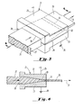
- FIG. 1 and 2 which illustrate the tapered die drawing apparatus and process for providing a tubular product with a wire core
- the various parts of the drawings are identified as follows: cylindrical tapered die 10 is shown with the tubular blank 11 having a wall thickness 11' with a central wire core 12.
- the initial polymer blank 11 after exiting from the die is depicted as 13 and the wire core as 14 after exit from die 10.
- Voltage source 15 in conjunction with electrical ground 16 illustrate the means for providing the electric field. It is understood that other means for providing the electric field are acceptable, such as providing a DC voltage of one polarity to the central core and a DC voltage of an opposite polarity to the tapered die. It is understood that the electric field can be of an intensity up to the breakdown voltage of the polymer blank under the particular processing conditions.
- die entrance opening 17 leads to the tapered section 18 of the die with tapered section 18 defining the stretching chamber 18' of the die which terminates adjacent to die exit opening 19 which defines and determines the approximate product thickness exiting at the chamber exit opening 19.
- the tubular product is being pulled or drawn through the die from a driven draw roll schematically shown as 20.
- the flat die 21 is comprised of top half 22 and botton half 23 with the two halves 22, 23 being electrically insulated from each other by electrical insulator 24.
- 25 depicts the voltage source and 26 the electrical ground.
- the film blank 27 of substantial rectangular cross sectional shape has thickness 27', enters entrance zone 28 and then passes into the tapered zone or stretching chamber 29 of the flat die 21, comprised of the opposed stationary surfaces from the die top half 22 and botton half 23. Exiting sheet or film 30 is then taken up by the driven drawing or stretching source roll shown schematically as 31 after passing exit zone 32 of the die.
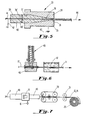
- Figure 5 depicts another embodiment of the film apparatus and process of this invention wherein a layered film having a metallic foil sandwiched therebetween is formed.
- Die 33 is comprised of upper half 34 and lower half 35 which defines the tapered zone or the stretching chamber 36 having entrance opening 37 and exit opening 38.
- the polymeric top blank 39 has thickness 39' and the lower polymeric blank 40 has thickness 40'.
- the two blanks 39 and 40 have electrically conducting foil 41 sandwiched therebetween and voltage source 42 is shown in conjunction with ground 43 as the means for providing the electrical field of sufficent intensity.
- the exiting film leaves through exit opening 38 and is pulled from the die with powered draw rolls 44.
- an annealing section is preferably provided between the exit of the particular die and the powered draw rolls.
- the upper half 34 of the die and lower half 35 of the die are not electrically insulated from each other, and the electric field is supplied by applying a DC voltage of one polarity to the foil 41 and a DC voltage of another polarity to the die, both of which are comprised of an electrically conductive material.
- the foil 41 or the die could be grounded and the other connected to a D.C. voltage source.
- Figure 6 is a schematic diagram that illustrates, in general, the preparation of the tubular blank.
- extruder 45 has die 46 which extrudes polymeric material around wire 11 which is then solidified in cooling bath 47 to provide the polymeric material blank 11.
- Figure 7 is a schematic diagram illustrating the stretching process of the invention with respect to a tubular product.
- Blank 11 is passed through oven 48 where it is heated to a temperature below the melting point of the polymeric material and it is then drawn through die 10 wherein it is drawn while being subjected to an electric field and then it passes through annealing section 49, through drawing device 50 and capstan guide rolls 51 and then to the winder 20.
- the final product is depicted as plastic tube 13 having wire core 14.
- a tubular brass die as depicted with reference to Figures 1 and 2 was utilized.
- the interior surfaces of the die formed an included angle of 14 degrees.
- the exit opening from the die was 0.110 inch in diameter and the land length was 0.1 inch.
- a polymer material blank was formed, utilizing a conventional screw extruder, from Kynar 7200, a commercially available copolymer of vinylidene fluoride and tetrafluoroethylene.
- the extruded undrawn polymer tubing had an outside diameter of 0.215 inches and a wall thickness 0.025 inches.
- Into this tubing was inserted a 14 gauge copper wire and the end of the tubing was stretched onto the wire to a thickness of about 0.110 inches.
- the tubing with the wire insert was then fed into the above die and pulled therefrom with the appropriate draw takeup roll.
- the tubing with the wire inserted was then drawn through the die which was maintained at a temperature of 50 degrees centigrade and the draw speed was 1 foot per minute.
- the total length of product wire core of about 30 feet was connected to a direct current voltage source maintained at 30,000 volts.
- the forming die which was comprised of an electrically conductive metal was electrically grounded.
- the oriented electrically treated (poled) sample was stored unshorted overnight. The ends of the sample were secured to prevent shrinkage of the insulation on the wire. The poled sample ends were released after a 24 hour exposure and the insulation shrank 10.3%.
- the tubular polymeric product with the wire core was then painted with a conductive paint and the piezoelectric hydrostatic d constant was 11 pc/N.
- the electrical connections were reversed from that employed in Example 1 and the voltage at the same level employed.
- the central core wire was connected to the electrical ground and the forming die was connected to the voltage source.
- the forming die had a land length of 0.750 inches and an exit opening of 0.100 inches.
- the entrance opening to the die was 0.75 inches and the working taper section of the die, the section of the die that actually made physical contact with the polymer blank, had an included angle of 10 degrees and was 1 inch in length.
- the die was formed of brass and the interior surfaces were polished to a smooth finish.
- a tubular blank similar to that in Example 1 was formed except that a 16 gauge wire was used as the central core.
- the stretching ratio provided within the stretching chamber of the die was 5.5 to 1.
- the piezoelectric polymer tubular product was post-treated similar to that in Example 1.
- the piezoelectric hydrostatic d constant was 12 pc/N.
- a commercially available Kynar 7200 polymer tube having a 16 gauge copper wire as the central core was prepared as the polmyer material blank.
- the outside diameter of the tube blank was 0.200.
- the product was pulled from the die at a rate of 6 inches per minute and the electrical field maintained.
- the die and the polymer tubular blank were maintained at a temperature of 82 degrees Centigrade and the product was annealed for 4 minutes at 82 degrees Centigrade thereby reducing the shrinkage to less than about 2%.
- the final product had a piezoelectric hydrostatic d h constant of 16.8 pc/N.
- This example illustrates the preparation of films by utilizing the apparatus as depicted in Fgiures 3 and 4.
- the Kynar 7200 polymer blank had a thickness of 0.125 inches and was fed into the apparatus that had an 8 degree included angle.
- the thickness of the blank was reduced to 0.030 inches providing a stretching ratio slightly in excess of 4.
- Example 4 is repeated except that the material blank is comprised of two sheets of polymeric material having a metal foil sandwiched therebetween.
- the electric field is provided during the stretching by connecting the foil to ground and the flat die to the high voltage source. Utilizing conditions similar to the foregoing examples, similar piezoelectric hydrostatic d constants are achieved.
- polymeric materials provide good polymer material blanks for use in the various processes and apparatus of the invention: a polymer or mixture of polymers selected from the group consisting essentially of polyvinylidene fluoride, polyvinyl fluoride, polyvinylchloride, polyamides, and copolymers or terpolymers containing a major portion of vinylidene fluoride with at least one copolymerizable monomer selected from the group consisting essentially of trifluoroethylene, tetrafluoroethylene and vinyl fluoride.
- Piezoelectric hydrostatic d constants in excess of 10 pc/N are readily achievable with all such polymeric materials under a variety of conditions whether prepared as a tubular product or as a film product of one or more layers.
- this invention allows poling of the material while drawing for a longer period of time than the prior art processes such as crushing between opposed pressure rolls where all the simultaneous drawing and poling takes place at the nip or in the neckdown area localized by heating of the blank.
Landscapes
- Engineering & Computer Science (AREA)
- Manufacturing & Machinery (AREA)
- Shaping By String And By Release Of Stress In Plastics And The Like (AREA)
- Extrusion Moulding Of Plastics Or The Like (AREA)
- Yarns And Mechanical Finishing Of Yarns Or Ropes (AREA)
Applications Claiming Priority (2)
| Application Number | Priority Date | Filing Date | Title |
|---|---|---|---|
| US59010684A | 1984-03-16 | 1984-03-16 | |
| US590106 | 1984-03-16 |
Publications (2)
| Publication Number | Publication Date |
|---|---|
| EP0156952A2 true EP0156952A2 (fr) | 1985-10-09 |
| EP0156952A3 EP0156952A3 (fr) | 1986-07-02 |
Family
ID=24360899
Family Applications (1)
| Application Number | Title | Priority Date | Filing Date |
|---|---|---|---|
| EP84112324A Withdrawn EP0156952A3 (fr) | 1984-03-16 | 1984-10-12 | Procédé d'étirage et appareillage pour films et tubes polymères piézoélectriques |
Country Status (3)
| Country | Link |
|---|---|
| US (1) | US4800048A (fr) |
| EP (1) | EP0156952A3 (fr) |
| JP (1) | JPS60196326A (fr) |
Cited By (4)
| Publication number | Priority date | Publication date | Assignee | Title |
|---|---|---|---|---|
| EP1215737A3 (fr) * | 2000-12-15 | 2005-05-11 | Matsushita Electric Industrial Co., Ltd. | Appareil de polarisation et procédé de polarisation pour un câble coaxial piézoélectrique flexible |
| EP1418633A4 (fr) * | 2001-08-02 | 2009-07-22 | Panasonic Corp | Polariseur de cable piezoelectrique souple coaxial, procede de polarisation, detecteur de defauts et procede de detection de defauts |
| GB2498433A (en) * | 2012-01-11 | 2013-07-17 | Univ Bolton | A polymer based piezoelectric fibre |
| EP2408034A4 (fr) * | 2009-03-13 | 2014-08-13 | Mitsui Chemicals Inc | Matériau polymère piézo-électrique, procédé de production et élément piézo-électrique |
Families Citing this family (10)
| Publication number | Priority date | Publication date | Assignee | Title |
|---|---|---|---|---|
| JPS61154931A (ja) * | 1984-12-28 | 1986-07-14 | Toa Nenryo Kogyo Kk | ポリオレフィン粉末より成形物を製造する方法 |
| US5192470A (en) * | 1986-02-27 | 1993-03-09 | Raytheon Company | Method of stretching and polarizing polymer materials |
| US5326393A (en) * | 1986-12-02 | 1994-07-05 | Solomat Partners, L.P. | Process for determining the actual temperature of a moldable material contained within a mold or passed through a die |
| US5271876A (en) * | 1986-12-02 | 1993-12-21 | Solomat Partners, L.P. | Process for analyzing, monitoring and/or controlling the internal structure of non-conductive, moldable material by inducing an electrical effect therein before it is molded |
| JP2881939B2 (ja) * | 1990-04-06 | 1999-04-12 | 住友電気工業株式会社 | 手術用縫合糸及びその製造方法 |
| CA2032015A1 (fr) * | 1990-12-11 | 1992-06-12 | Martin Perlman | Methode de duplication des constantes piezoelectriques et pyroelectriques des pellicules de polyfluorure de vinylidene (pvdf) |
| US5407616A (en) * | 1991-12-19 | 1995-04-18 | E. I. Du Pont De Nemours And Company | Method for making cylindrical preforms |
| US5494617A (en) * | 1994-05-16 | 1996-02-27 | The United States Of America As Represented By The Secretary Of The Navy | Method of inducing piezoelectric properties in polymers |
| DE10083893T1 (de) * | 1999-01-28 | 2002-06-06 | Bridgestone Corp | Lineares Beleuchtungssystem, Verfahren zur Herstellung desselben und Abtastvorrichtung |
| JP3742574B2 (ja) * | 2001-09-10 | 2006-02-08 | 弘二 大東 | 強誘電性高分子膜の製造方法 |
Family Cites Families (8)
| Publication number | Priority date | Publication date | Assignee | Title |
|---|---|---|---|---|
| US3290420A (en) * | 1962-07-05 | 1966-12-06 | Columbian Rope Co | Process for making thin oriented plastic strips and tape |
| US3275730A (en) * | 1962-12-24 | 1966-09-27 | Hercules Inc | Method and apparatus for orienting an extruded polymeric wire coating |
| US3417176A (en) * | 1964-12-24 | 1968-12-17 | Haveg Industries Inc | Process of forming heat shrinkable perfluorocarbon polymer tubing and shapes |
| FR2490877A1 (fr) * | 1980-09-19 | 1982-03-26 | Thomson Csf | Procede de fabrication de films polymeres piezoelectriques |
| FR2519503B1 (fr) * | 1981-12-31 | 1991-09-06 | Thomson Csf | Transducteurs piezoelectriques polymeres et procede de fabrication |
| DE3370251D1 (en) * | 1982-03-18 | 1987-04-16 | British Telecomm | Piezoelectric and pyroelectric film |
| DE3275421D1 (en) * | 1982-03-29 | 1987-03-12 | Rhodia Ag | Process and apparatus for the manufacture of electret filaments, fibres or the like |
| GB2123602B (en) * | 1982-07-06 | 1987-02-25 | Raytheon Co | Piezo electric transducer and method of making same |
-
1984
- 1984-10-12 EP EP84112324A patent/EP0156952A3/fr not_active Withdrawn
-
1985
- 1985-02-01 JP JP60016710A patent/JPS60196326A/ja active Pending
-
1987
- 1987-11-30 US US07/126,993 patent/US4800048A/en not_active Expired - Fee Related
Cited By (5)
| Publication number | Priority date | Publication date | Assignee | Title |
|---|---|---|---|---|
| EP1215737A3 (fr) * | 2000-12-15 | 2005-05-11 | Matsushita Electric Industrial Co., Ltd. | Appareil de polarisation et procédé de polarisation pour un câble coaxial piézoélectrique flexible |
| EP1418633A4 (fr) * | 2001-08-02 | 2009-07-22 | Panasonic Corp | Polariseur de cable piezoelectrique souple coaxial, procede de polarisation, detecteur de defauts et procede de detection de defauts |
| EP2408034A4 (fr) * | 2009-03-13 | 2014-08-13 | Mitsui Chemicals Inc | Matériau polymère piézo-électrique, procédé de production et élément piézo-électrique |
| GB2498433A (en) * | 2012-01-11 | 2013-07-17 | Univ Bolton | A polymer based piezoelectric fibre |
| GB2498433B (en) * | 2012-01-11 | 2016-08-03 | Univ Of Bolton | Piezoelectric fibre and method of production thereof |
Also Published As
| Publication number | Publication date |
|---|---|
| US4800048A (en) | 1989-01-24 |
| JPS60196326A (ja) | 1985-10-04 |
| EP0156952A3 (fr) | 1986-07-02 |
Similar Documents
| Publication | Publication Date | Title |
|---|---|---|
| US4800048A (en) | Die drawing process and apparatus for piezoelectric polymer films and tubes | |
| EP0089770B1 (fr) | Film piezoélectrique et pyroélectrique | |
| EP0146273A2 (fr) | Câble coaxial piézoélectrique | |
| US4427609A (en) | Process for producing piezoelectric polymer films | |
| US3068528A (en) | Method for conveying and stretching thermoplastic film | |
| DE2235500B2 (de) | Verfahren zur Herstellung einer Folie aus Polyvinylidenfluorid | |
| CN1315633C (zh) | 用于转变结晶或半结晶聚合物的方法和设备 | |
| US4134957A (en) | Method of stretching polypropylene films | |
| US3417176A (en) | Process of forming heat shrinkable perfluorocarbon polymer tubing and shapes | |
| US3158181A (en) | Polymeric tubate product and process | |
| US4481158A (en) | Extrusion of films of vinylidene fluoride polymers | |
| GB2047620A (en) | Method for continuously stretching plastic film | |
| DE1504142A1 (de) | Verfahren und Vorrichtung zur Herstellung von Kunststoffrohren | |
| DE1704762B2 (de) | Verwendung einer Vinylidenfluoridpolymerisat-Folie als Dielektrikum | |
| EP0050332A1 (fr) | Procédé de polarisation par décharge couronne | |
| DE3620219A1 (de) | Verfahren zur herstellung von biaxial gestreckten folien sowie vorrichtung zur durchfuehrung des verfahrens | |
| JPS5922378A (ja) | 圧電変換器及びその製造方法 | |
| JPH07314552A (ja) | 熱可塑性樹脂フィルムの製造方法 | |
| CH672094A5 (fr) | ||
| EP0515387B1 (fr) | Procede de fabrication de cable isole par du polytetrafluoroethylene de faible densite | |
| DE2965120D1 (en) | Process for the manufacture of flat thermoplastic films having improved dimensional stability | |
| EP0237709A1 (fr) | Feuille de PVDF à phase bêta, produite par coulage sur un support isolant, préparé spécialement | |
| WO1984000717A1 (fr) | Fabrication de cables ayant une isolation de polytetrafluoroethylene fritte de faible densite | |
| JPS635891B2 (fr) | ||
| DE1504523A1 (de) | Zweiachsig orientierter Polypropylenfilm |
Legal Events
| Date | Code | Title | Description |
|---|---|---|---|
| PUAI | Public reference made under article 153(3) epc to a published international application that has entered the european phase |
Free format text: ORIGINAL CODE: 0009012 |
|
| AK | Designated contracting states |
Designated state(s): BE DE FR GB IT |
|
| PUAL | Search report despatched |
Free format text: ORIGINAL CODE: 0009013 |
|
| AK | Designated contracting states |
Kind code of ref document: A3 Designated state(s): BE DE FR GB IT |
|
| 17P | Request for examination filed |
Effective date: 19861104 |
|
| 17Q | First examination report despatched |
Effective date: 19880211 |
|
| STAA | Information on the status of an ep patent application or granted ep patent |
Free format text: STATUS: THE APPLICATION IS DEEMED TO BE WITHDRAWN |
|
| 18D | Application deemed to be withdrawn |
Effective date: 19880622 |
|
| RIN1 | Information on inventor provided before grant (corrected) |
Inventor name: FERREN, RICHARD ANTHONY Inventor name: BLOOMFIELD, PHILIP EARL Inventor name: WICKWIRE, DEAN HEDGE |