EP0157059A1 - Vorrichtung zur Aufnahme einer axialen Kraft auf eine drehende Achse - Google Patents
Vorrichtung zur Aufnahme einer axialen Kraft auf eine drehende Achse Download PDFInfo
- Publication number
- EP0157059A1 EP0157059A1 EP84402603A EP84402603A EP0157059A1 EP 0157059 A1 EP0157059 A1 EP 0157059A1 EP 84402603 A EP84402603 A EP 84402603A EP 84402603 A EP84402603 A EP 84402603A EP 0157059 A1 EP0157059 A1 EP 0157059A1
- Authority
- EP
- European Patent Office
- Prior art keywords
- rotating shaft
- shaft
- toothed
- pinions
- axial
- Prior art date
- Legal status (The legal status is an assumption and is not a legal conclusion. Google has not performed a legal analysis and makes no representation as to the accuracy of the status listed.)
- Withdrawn
Links
- 238000001125 extrusion Methods 0.000 description 6
- 210000002105 tongue Anatomy 0.000 description 3
- 230000006978 adaptation Effects 0.000 description 1
- 238000005452 bending Methods 0.000 description 1
- 230000007423 decrease Effects 0.000 description 1
- 230000000694 effects Effects 0.000 description 1
- 238000009434 installation Methods 0.000 description 1
- 238000003754 machining Methods 0.000 description 1
- 238000004519 manufacturing process Methods 0.000 description 1
- 210000000056 organ Anatomy 0.000 description 1
- 230000003071 parasitic effect Effects 0.000 description 1
- 230000000717 retained effect Effects 0.000 description 1
Images

Classifications
-
- F—MECHANICAL ENGINEERING; LIGHTING; HEATING; WEAPONS; BLASTING
- F16—ENGINEERING ELEMENTS AND UNITS; GENERAL MEASURES FOR PRODUCING AND MAINTAINING EFFECTIVE FUNCTIONING OF MACHINES OR INSTALLATIONS; THERMAL INSULATION IN GENERAL
- F16H—GEARING
- F16H1/00—Toothed gearings for conveying rotary motion
- F16H1/02—Toothed gearings for conveying rotary motion without gears having orbital motion
- F16H1/20—Toothed gearings for conveying rotary motion without gears having orbital motion involving more than two intermeshing members
- F16H1/206—Toothed gearings for conveying rotary motion without gears having orbital motion involving more than two intermeshing members characterised by the driving or driven member being composed of two or more gear wheels
-
- F—MECHANICAL ENGINEERING; LIGHTING; HEATING; WEAPONS; BLASTING
- F16—ENGINEERING ELEMENTS AND UNITS; GENERAL MEASURES FOR PRODUCING AND MAINTAINING EFFECTIVE FUNCTIONING OF MACHINES OR INSTALLATIONS; THERMAL INSULATION IN GENERAL
- F16C—SHAFTS; FLEXIBLE SHAFTS; ELEMENTS OR CRANKSHAFT MECHANISMS; ROTARY BODIES OTHER THAN GEARING ELEMENTS; BEARINGS
- F16C19/00—Bearings with rolling contact, for exclusively rotary movement
- F16C19/54—Systems consisting of a plurality of bearings with rolling friction
-
- F—MECHANICAL ENGINEERING; LIGHTING; HEATING; WEAPONS; BLASTING
- F16—ENGINEERING ELEMENTS AND UNITS; GENERAL MEASURES FOR PRODUCING AND MAINTAINING EFFECTIVE FUNCTIONING OF MACHINES OR INSTALLATIONS; THERMAL INSULATION IN GENERAL
- F16C—SHAFTS; FLEXIBLE SHAFTS; ELEMENTS OR CRANKSHAFT MECHANISMS; ROTARY BODIES OTHER THAN GEARING ELEMENTS; BEARINGS
- F16C39/00—Relieving load on bearings
- F16C39/02—Relieving load on bearings using mechanical means
-
- F—MECHANICAL ENGINEERING; LIGHTING; HEATING; WEAPONS; BLASTING
- F16—ENGINEERING ELEMENTS AND UNITS; GENERAL MEASURES FOR PRODUCING AND MAINTAINING EFFECTIVE FUNCTIONING OF MACHINES OR INSTALLATIONS; THERMAL INSULATION IN GENERAL
- F16C—SHAFTS; FLEXIBLE SHAFTS; ELEMENTS OR CRANKSHAFT MECHANISMS; ROTARY BODIES OTHER THAN GEARING ELEMENTS; BEARINGS
- F16C2361/00—Apparatus or articles in engineering in general
- F16C2361/61—Toothed gear systems, e.g. support of pinion shafts
Definitions
- the subject of the invention is a device which has the role of collecting or in other words counterbalancing an axial load which is exerted on a rotating shaft.
- a known conventional solution then consists in using several stops with reduced transverse dimensions as a function of the space available and in mounting them one after the other along the shaft. This means is rarely satisfactory because the force is unevenly distributed between the successive stops, so that the most loaded deteriorates prematurely.
- the main object of the invention is to provide a device which allows a axial stop which can be exerted on a rotating shaft on which it is not possible to directly mount a stop of dimensions to be supported by a suitably dimensioned single stop. sufficient.
- this axial force is distributed between the toothed pinions and transmitted by these to the toothed wheels in the form of a couple having a tangential component and an axial component. Due to the inclination in opposite directions of the teeth, the tangential components are in opposite directions and cancel each other out and the axial components are in the same direction and add up. Their total, equal to the axial force, is collected by the single stop of the secondary shaft on which the axial force is thus transferred.
- the device of the invention can be used both when the rotating shaft does not transmit rotational torque as when it constitutes a drive shaft transmitting a drive torque, or a receiving shaft supporting a resistive torque, or simply a intermediate shaft transmitting a torque and receiving an axial load from the member or the machine it drives.
- the secondary shaft can be left free to rotate by simply being driven by the rotating shaft, but it can also serve as a shaft driving the rotating shaft.
- the toothed pinions wedged on the rotating shaft are directly engaged with the toothed wheels of the secondary shaft with axial stop. It is possible to mesh each of the two pinions of the rotating shaft with intermediate pinions themselves meshing with the toothed wheels.
- these intermediate pinions can be satellite pinions arranged around the shaft rotating and carried by a fixed planet carrier. The set of these planet gears then meshes with an internally toothed ring which surrounds the rotating shaft and which is retained in the axial direction by a single stop in an axial direction or in each of the two axial directions.
- This toothed ring can be given a sufficient diameter so that it contains near the rotating shaft a second rotating shaft arranged in parallel. Such an assembly is useful for example for driving the two screws of an extruder.
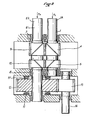
- the axial force FA is distributed between the toothed pinions 4, 5 in forces which are transmitted to the toothed wheels 9,10 where they can be broken down on each of them into an axial force F 1 , F 2 respectively and a tangential force T 1 , T 2 respectively.
- the axial forces F 1 , F 2 are directed in the same direction while the tangential forces T 1 and T 2 give rise to opposite couples which cancel each other out.
- F 1 + F 2 FA; thus the force FA is transferred without any other consequence to the secondary shaft 6.
- the toothed wheels 9, 10 can be given a diameter large enough so that the secondary shaft 6 can be separated enough from the rotating shaft 1 and l 'Equip with a single axial stop 11 of suitable dimensions so that it alone supports the sum F 1 + F 2 .
- axial stop 11 a roller bearing, for example, commercially available.
- FIG. 1 there is shown on the secondary shaft 6 an opposite axial stop 11 'to allow rotation of the shaft 1 in both directions.
- the secondary shaft 6 has been extended by a dashed line downwards in FIG. 1 to show that this shaft 6 can also be used for the input of a motor torque for the purpose of driving the shaft 1 in rotation. If this driving torque gives rise to an axial component on the secondary shaft 6, this is also supported by the axial stops 11 and 11 ′ or, depending on the direction of the torque and the inclination of the teeth, it increases or decreases the sum F 1 + F 2 .
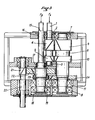
- Figure 2 relates to an arrangement similar to that of Figure 1 where we recognize the shaft 1 with its two pinions 4, 5, a secondary shaft 6 'with its two toothed wheels 9,10 and its two bearings 7 , 8. But this secondary shaft 6 'is extended beyond its two bearings 7, 8. On the side of the bearing 8, the secondary shaft 6' extends farther than the shaft 1 and it is provided with a toothed wheel 12, the diameter of which can be fixed at will; this toothed wheel 12 meshes with a toothed pinion 13, fixed in rotation on a drive shaft 14. The toothed wheel 12 is locked in rotation and in translation on the secondary shaft 6 'and the axial stops 11, 11' are arranged on the side and on the other side of this toothed wheel 12.
- This embodiment makes it possible to bring the two shafts 1 and 6 'closer together, so that, on the side opposite to that on which the gear wheel 12 is located, the two end parts 1A and 6'A of the shafts 1 and 6 are obtained '' which can be coupled directly to the driven shafts of the screws of a 2-screw extruder.
- the two extrusion screws generate two axial forces FA and FB.
- the axial force FA exerted on the shaft 1 is transferred to the shaft 6 ', as explained above, where it is added to the axial force FB exerted directly on the shaft 6'.
- the two axial forces FA and FB are collected by the axial stop 11.
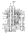
- FIG. 3 relates to a reduction gear for an extrusion machine, where we can once again recognize the rotating shaft 1 supported by its two bearings 2, 3, provided with two toothed pinions 4, 5 with opposite inclinations, to which is associated with the secondary shaft 6 supported by its two bearings 7, 8 and provided with its two toothed wheels 9, 10 which respectively mesh with the toothed pinions 4, 5.
- the first rotating shaft 1 is coupled to a first extrusion screw and the axial force which is exerted by this extrusion screw on the shaft 1 is transferred to the secondary shaft 6, the latter is provided for this purpose with an axial stop li.
- second rotating shaft 15 close to the first rotating shaft 1, which is freely supported in rotation by three bearings 16, 17, 18 and which is coupled to a second extrusion screw.
- This second rotating shaft 15 is longer than the first rotating shaft 1 so that it can be provided, beyond the latter, with an axial stop 19, identical to the axial stop 11 of the secondary shaft 6, to receive the axial thrust FB created by the second extrusion screw.
- a drive shaft 20 is provided with a toothed pinion 21, with inclined teeth, which meshes with a toothed wheel 22 wedged on the second rotating shaft 15. On the latter is wedged a toothed pinion 23 which meshes with an additional toothed wheel 24 wedged on the secondary shaft 6.
- the engine torque from the drive shaft 20 is transmitted to the second shaft 15 then from the latter to the secondary shaft 6 and finally to the first rotating shaft 1.
- the first rotating shaft 1 and the second rotating shaft 15 rotate in the same direction.
- the toothed pinion 23 and the toothed wheel 24 would no longer be engaged but would be connected in rotation by a parasitic pinion engaged on one side with the toothed pinion 23, on the other with the gear 24.
- the transfer of the axial load from the rotating shaft 1 to the secondary shaft 6 takes place directly from the first to the second. It is possible to interpose one or more intermediate gears between them when you want to increase the distance between them.
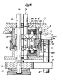
- FIG. 4 relates to an example in which we find the rotating shaft 1 supported by its bearings 2, 3 and provided with its toothed pinions 4.5.
- the latter each mesh respectively with three intermediate pinions 25A, 25B, 25C and 26A, 26B, 26C.
- These two sets of three intermediate pinions are satellite pinions mounted on the same planet carrier 27 immobilized in rotation. All the intermediate satellite pinions 25A to 25C and 26A to 26C are surrounded by a ring 28 having two distinct internal toothing 29, 30 with which the two sets of pinions mesh respectively.
- This ring 28 is guided in rotation in ball bearings 31 and immobilized in translation by axial stops 32 and 32 '.
- This alternative embodiment gives the possibility of mounting a second rotating shaft 33 near the first rotating shaft 1, inside the crown 28.
- This second shaft 33 is parallel to the first shaft 1 and it extends outside the crown 28 further than the first shaft 1 where it is provided with a toothed wheel 34.
- the crown 28 is provided with an external toothing 35.
- a drive shaft 36 is equipped with two pinions 37 and 38 which mesh respectively with one the toothed wheel 34 of the second shaft 33, the other with the external toothing 35 of the crown 28.
- the rotational drive of the first rotating shaft 1 takes place via the crown 28 and the pinions 25A -C, 26A-C and 4, 5 at the same time as the rotational centering of the second rotating shaft 33 which is done by means of the toothed wheel 34.
- the axial force FB which is exerted on the second shaft turning 33 is collected by a single axial stop 39 placed behind the toothed wheel 34 where the available space allows to give it the desired diameter.
- FIG. 6 relates to an exemplary embodiment which is substantially the same as that of FIGS. 4 and 5. For this reason, the same reference numerals have been used to designate the same parts therein, and we will now limit us to describing only the differences .
- the crown 28 is made in two parts 28A, 28B which succeed one another in the axial direction, one 28A having the internal toothing 30 which meshes with the play of the three planet gears 25A to 25C as well as the external toothing 35 which meshes with the pinion 38, the other 28B carrying the internal toothing 29 which meshes with the play of the three planet gears 26A to 26C.
- These two parts 28A, 28B each have an external toothing 40, 41 respectively near their neighboring ends.
- the ring 28 also includes a ring 28C which surrounds the two parts 28A, 28B in the region of their teeth 40, 41.
- This ring 28C has two internal teeth 42, 43 which each mesh respectively with the external teeth 40, 41 of the parts 28A , 28B.
- the toothings 4 0 4 1 were bent; there is therefore a possibility of play in the transverse direction between the parts 28A and 28B and, thus, between the teeth carried by these two parts joined in rotation by the ring 28C.
- an Oldham seal 44 is used to connect the planet carrier 27 to the fixed wall 45 of the casing which contains the entire device.
- This seal 44 has on one side a tongue 46 slidably mounted in a corresponding groove made in the wall 45; it also has on its opposite side three tongues 47 orthogonal to the tongue 46 and mounted sliding each in a corresponding respective groove formed in the planet carrier 27. In this way, the whole of the latter can adapt its position relative to the tree 1.
- the operating clearances thus produced authorize the machining of the teeth with the current manufacturing tolerances.
- each is associated with a respective secondary shaft to support the axial load as explained.
Landscapes
- Engineering & Computer Science (AREA)
- General Engineering & Computer Science (AREA)
- Mechanical Engineering (AREA)
- Gear Transmission (AREA)
- Retarders (AREA)
Applications Claiming Priority (2)
| Application Number | Priority Date | Filing Date | Title |
|---|---|---|---|
| FR8320199 | 1983-12-16 | ||
| FR8320199A FR2556795A1 (fr) | 1983-12-16 | 1983-12-16 | Dispositif pour encaisser une charge axiale sur un arbre tournant |
Publications (1)
| Publication Number | Publication Date |
|---|---|
| EP0157059A1 true EP0157059A1 (de) | 1985-10-09 |
Family
ID=9295264
Family Applications (1)
| Application Number | Title | Priority Date | Filing Date |
|---|---|---|---|
| EP84402603A Withdrawn EP0157059A1 (de) | 1983-12-16 | 1984-12-14 | Vorrichtung zur Aufnahme einer axialen Kraft auf eine drehende Achse |
Country Status (3)
| Country | Link |
|---|---|
| EP (1) | EP0157059A1 (de) |
| JP (1) | JPS60201140A (de) |
| FR (1) | FR2556795A1 (de) |
Cited By (1)
| Publication number | Priority date | Publication date | Assignee | Title |
|---|---|---|---|---|
| EP2284394A1 (de) * | 2009-08-10 | 2011-02-16 | Hansen Transmissions International, Naamloze Vennotschap | Parallelgetriebeeinheit für einen Getriebekasten für ein Windrad |
Citations (5)
| Publication number | Priority date | Publication date | Assignee | Title |
|---|---|---|---|---|
| US1536092A (en) * | 1921-05-12 | 1925-05-05 | Westinghouse Electric & Mfg Co | Power-transmission gearing |
| DE1053270B (de) * | 1955-06-15 | 1959-03-19 | Gewerk Eisenhuette Westfalia | Zahnraedergetriebe mit Schraegverzahnung |
| FR2011374A1 (de) * | 1968-06-21 | 1970-02-27 | Bbc Brown Boveri & Cie | |
| FR2234490A1 (en) * | 1973-06-20 | 1975-01-17 | Bhs Bayerische Berg | Compressor drive gear with central wheel - has pinion shafts equipped with thrust rings |
| GB2078332A (en) * | 1980-06-12 | 1982-01-06 | Voith Getriebe Kg | A spur gear transmission system |
-
1983
- 1983-12-16 FR FR8320199A patent/FR2556795A1/fr not_active Withdrawn
-
1984
- 1984-12-14 EP EP84402603A patent/EP0157059A1/de not_active Withdrawn
- 1984-12-14 JP JP59263067A patent/JPS60201140A/ja active Pending
Patent Citations (5)
| Publication number | Priority date | Publication date | Assignee | Title |
|---|---|---|---|---|
| US1536092A (en) * | 1921-05-12 | 1925-05-05 | Westinghouse Electric & Mfg Co | Power-transmission gearing |
| DE1053270B (de) * | 1955-06-15 | 1959-03-19 | Gewerk Eisenhuette Westfalia | Zahnraedergetriebe mit Schraegverzahnung |
| FR2011374A1 (de) * | 1968-06-21 | 1970-02-27 | Bbc Brown Boveri & Cie | |
| FR2234490A1 (en) * | 1973-06-20 | 1975-01-17 | Bhs Bayerische Berg | Compressor drive gear with central wheel - has pinion shafts equipped with thrust rings |
| GB2078332A (en) * | 1980-06-12 | 1982-01-06 | Voith Getriebe Kg | A spur gear transmission system |
Cited By (5)
| Publication number | Priority date | Publication date | Assignee | Title |
|---|---|---|---|---|
| EP2284394A1 (de) * | 2009-08-10 | 2011-02-16 | Hansen Transmissions International, Naamloze Vennotschap | Parallelgetriebeeinheit für einen Getriebekasten für ein Windrad |
| CN101994781A (zh) * | 2009-08-10 | 2011-03-30 | 汉森传动系统国际公司 | 用于风轮机用齿轮箱的平行齿轮单元 |
| US8794094B2 (en) | 2009-08-10 | 2014-08-05 | Hansen Transmissions International N.V. | Parallel gear unit for a gearbox for a wind turbine |
| CN101994781B (zh) * | 2009-08-10 | 2014-12-24 | Zf风能安特卫普有限公司 | 用于风轮机用齿轮箱的平行齿轮单元 |
| AU2010206051B2 (en) * | 2009-08-10 | 2015-02-05 | Zf Wind Power Antwerpen Nv | Parallel gear unit for a gearbox for a wind turbine |
Also Published As
| Publication number | Publication date |
|---|---|
| JPS60201140A (ja) | 1985-10-11 |
| FR2556795A1 (fr) | 1985-06-21 |
Similar Documents
| Publication | Publication Date | Title |
|---|---|---|
| EP0729399B1 (de) | Teleskopisches system | |
| EP0588769B2 (de) | Planeten-Untersetzungsgetrieb | |
| EP1347207B1 (de) | Linearantrieb mit Gewinderollen | |
| FR2527132A1 (fr) | Tete articulee pour robot industriel | |
| FR2817823A1 (fr) | Dispositif actionneur pour un derailleur de bicyclette, avec accouplement relie a l'arbre mene | |
| EP0863331A2 (de) | Planetuntersetzungsgetriebe mit entgegengesetzten Schrägverzahnungen | |
| EP0122208B1 (de) | Vorrichtung zum Übertragen der Drehbewegung einer Antriebsachse zu einer Abtriebsachse | |
| FR2613012A1 (fr) | Renvoi d'angle a pignons coniques, notamment pour machines agricoles | |
| FR2610058A1 (fr) | Dispositif de transmission de puissance avec reduction de vitesse entre un ensemble tournant et un arbre monte coaxial a l'interieur de celui-ci | |
| FR2744192A1 (fr) | Differentiel a appui interne des pignons satellites | |
| FR2556795A1 (fr) | Dispositif pour encaisser une charge axiale sur un arbre tournant | |
| EP0118358A1 (de) | Getriebe zum Antrieb eines Doppelschneckenextruders | |
| FR2837773A1 (fr) | Appareil de direction du vehicule | |
| FR2634711A1 (fr) | Transmission d'essieu pour vehicules sur rails notamment | |
| EP0281847B1 (de) | Zahnärztliches Handstück | |
| FR2561341A1 (fr) | Reducteur de vitesse a composantes axiales et transversales equilibrees | |
| FR2771153A1 (fr) | Reducteur epicycloidal ou cycloidal et articulation de robot equipee d'un tel reducteur | |
| FR2564058A1 (fr) | Systeme de transmission principal, pour un helicoptere | |
| EP0733832A1 (de) | Automatisches Sperrdifferential | |
| FR3129446A1 (fr) | Système réducteur à engrenages et bagues dentées pour un moteur d’un ensemble occultant où le système réducteur présente un bruit de fonctionnement réduit | |
| EP0283389B1 (de) | Bedienungseinrichtung eines Differentials mit hydraulisch geregeltem Schlupf und ein damit ausgestattetes Fahrzeug | |
| EP0090326A1 (de) | Vorrichtung für die Montage eines Hohlrades in Planetengetrieben | |
| FR2667374A1 (fr) | Dispositif de transmission d'un couple d'entrainement d'une roue motrice de vehicule automobile avec un roulement et un reducteur de vitesse integres a la roue. | |
| FR2574145A1 (fr) | Dispositif pour la transmission d'un mouvement rotatif,notamment sur une machine-outil | |
| EP1331355A1 (de) | Vorrichtung zur Blockierung einer Rolladenwickelwelle |
Legal Events
| Date | Code | Title | Description |
|---|---|---|---|
| PUAI | Public reference made under article 153(3) epc to a published international application that has entered the european phase |
Free format text: ORIGINAL CODE: 0009012 |
|
| 17P | Request for examination filed |
Effective date: 19841221 |
|
| AK | Designated contracting states |
Designated state(s): AT BE CH DE GB IT LI LU NL SE |
|
| STAA | Information on the status of an ep patent application or granted ep patent |
Free format text: STATUS: THE APPLICATION IS DEEMED TO BE WITHDRAWN |
|
| 18D | Application deemed to be withdrawn |
Effective date: 19870331 |
|
| RIN1 | Information on inventor provided before grant (corrected) |
Inventor name: POULIN, JEAN-LOUIS |