EP0157073B1 - Organe de préhension pour vérin - Google Patents
Organe de préhension pour vérin Download PDFInfo
- Publication number
- EP0157073B1 EP0157073B1 EP84850356A EP84850356A EP0157073B1 EP 0157073 B1 EP0157073 B1 EP 0157073B1 EP 84850356 A EP84850356 A EP 84850356A EP 84850356 A EP84850356 A EP 84850356A EP 0157073 B1 EP0157073 B1 EP 0157073B1
- Authority
- EP
- European Patent Office
- Prior art keywords
- gripper
- base plate
- load
- rocker
- jaws
- Prior art date
- Legal status (The legal status is an assumption and is not a legal conclusion. Google has not performed a legal analysis and makes no representation as to the accuracy of the status listed.)
- Expired
Links
- 230000001154 acute effect Effects 0.000 claims description 2
- 238000004873 anchoring Methods 0.000 claims description 2
- 239000004809 Teflon Substances 0.000 description 3
- 229920006362 Teflon® Polymers 0.000 description 3
- 230000006835 compression Effects 0.000 description 2
- 238000007906 compression Methods 0.000 description 2
- 230000000284 resting effect Effects 0.000 description 2
- 229910000831 Steel Inorganic materials 0.000 description 1
- 230000003247 decreasing effect Effects 0.000 description 1
- 230000001419 dependent effect Effects 0.000 description 1
- 230000001681 protective effect Effects 0.000 description 1
- 230000000717 retained effect Effects 0.000 description 1
- 230000002441 reversible effect Effects 0.000 description 1
- 239000010959 steel Substances 0.000 description 1
Images



Classifications
-
- B—PERFORMING OPERATIONS; TRANSPORTING
- B66—HOISTING; LIFTING; HAULING
- B66F—HOISTING, LIFTING, HAULING OR PUSHING, NOT OTHERWISE PROVIDED FOR, e.g. DEVICES WHICH APPLY A LIFTING OR PUSHING FORCE DIRECTLY TO THE SURFACE OF A LOAD
- B66F1/00—Devices, e.g. jacks, for lifting loads in predetermined steps
- B66F1/02—Devices, e.g. jacks, for lifting loads in predetermined steps with locking elements, e.g. washers, co-operating with posts
- B66F1/025—Devices, e.g. jacks, for lifting loads in predetermined steps with locking elements, e.g. washers, co-operating with posts the devices being operated by fluid pressure
Definitions
- the invention relates to a gripper for moving heavy loads.
- Grippers of this kind are known e.g. from US-A-3 203 669 and include at least one hydraulic cylinder, which at one end is intended to be anchored at a support point, and at its other end is pivotably connected to a movable part, there being arranged at the movable part opposing coneiform jaws for gripping the load between themselves in the movable part, there being seatings with guide surfaces for urging the jaws to, and away from, the load in response to the thrust or withdrawal of the hydraulic cylinder ram.
- the loads in question here are in order of magnitude of tens of tonnes.
- a disadvantage with the known gripper is that they cannot directly grip the load which is to be moved, and each gripper requires a separate pull rod, in which the load is anchored and around which the gripper grips. Under the action of at least one hydraulic cylinder the gripper then moves the pull rod with short distances corresponding to the stroke of the hydraulic cylinders, and the pull rod thus pulls the load after it.
- Another disadvantage with the known gripper is that they do not afford satisfactory gripping of elongate loads, e.g. beams or girders of varying width, e.g. such as being tapered or are conical along their length.
- the known grippers require a pull rod with a constant cross-section along its length.
- Another disadvantage with the known gripper is that they are mounted in a cradle for taking up angular variations in the load, e.g. such as occur when the free end of a beam in a horizontal position sways as it is moved by the gripper, or when a load lifted vertically upwards by the gripper starts to swing.
- a cradle requires complicated means for anchoring the cradle and thereby the gripper at a fixed point, e.g. a foundation.
- the grippers in the art do not allow moving an elongate load which forms an angle to the longitudinal axis of the gripper.
- the present invention has the object of achieving a gripper of the kind discussed in the introduction, which is not burdened with the above- mentioned disadvantages.
- the gripper in accordance with the invention shall thus be able directly to grip the load which is to be moved, and thereby make unnecessary the use of separate pull rods or steel ropes with which the load is anchored.
- the inventive gripper shall further be able to grip loads having varying cross-section along their length.
- the inventive gripper shall be able to accommodate angular variations in the load, thereby avoiding the need of a separate cradle, thus enabling the conventional hydraulic cylinders associated with the gripper to be attached directly to a substructure in the case where the gripper is stationary and moves a load.
- the gripper can be fastened directly to the load in the case where the gripper moves along a beam or some other stationary member while pushing or pulling the load in front of or behind itself.
- the gripper in accordance with the invention shall permit movement of the load both vertically and horizontally.
- the gripper shall be able to pull itself forward on a stationary substructure, e.g. a rail, by gripping it while moving the load.
- a slab of Teflon is preferably placed between the gripper and the stationary substructure, e.g. the rail, and the whole unit, Teflon slab and gripper, will then serve as a bearing between the load carried by the gripper and the substructure, whereby the need of separate bearing means, e.g. conventional rollers, is avoided to a large extent.
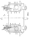
- the invention gripper illustrated in Figure 1 includes a movable part in the form of a flat rectangular base plate 1 with two lugs 2, 3 to which hydraulic cylinders are pivotably attached with the aid of pins 4, 5.
- Two seatings or rockers 6, 7 are pivotably attached to the base plate 1, such that they are opposite each other and symmetrical about a center line 8.
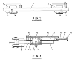
- the rockers 6 and 7 are pivotably mounted in the base plate by pivot pins 9 and 10, which have a shrinkfit in the rockers and extend through the base plate 1, on the underside of which they are retained with the aid of retaining plates 11 and 12 and bolts 13 and 14, threaded in the respective pin 9 and 10.
- Each rocker 6 and 7 is a plate configured substantially as a right-angled triangle with a cross portion 15 and 16 instead of its acute angle, integral with the rest of the plate and at right angles to the hypotenuse of the triangle.
- the hypotenuse forms a guide surface 17 and 18 for a wedging jaw 19 and 20.
- Each jaw is a flat plate in the form of a truncated, substantially right-angular triangle with its hypotenuse provided with serrations 21 and 22.
- the points of the serrations are directed in the direction of travel for the unillustrated load, this direction being indicated by the arrow 23 in Figure 1.
- the (geometrical) adjacent side of each jaw 19 and 20 forms a surface engaging against the respective guide surface 17 and 18.
- Each jaw 19 and 20 is glidable along the respective guide surface 17 and 18, under the guidance of a guide rod 24 and 25 extending with clearance through holes 26 and 27 in the cross portion 15 and 16.
- Each guide pin 24 and 25 is threaded into the (geometrical) opposite side 28 and 29 of the jaw 19 and 20.
- a compression spring 30 and 31 is biased to thrust the respective jaw in a direction contrary to that of the arrow 23.
- the movement of the jaws in said direction is limited by adjustment nuts 32 and 33, which are screwed onto the respective threaded guide rod 24 and 25.
- Each rod is provided with a cross handle 34 and 35.
- the pivot pin 10 is a shrink fit in a hole 43 through the rocker 7.
- the pin 10, non-rotatably attached to the rocker 7, passes with clearance through a hole 45 in the base plate 1, as previously mentioned.
- the pin 9 passes with clearance through a schematically illustrated hole 44 in the base plate.
- Each rocker with associated jaw is covered by a protective plate 46 and 47 to form a jaw housing.
- the function of a known gripper is explained with the aid of Figure 4.
- the known gripper 48 includes two pairs of jaws 49, 50 alternatingly gripping a pull rod 51, and by unillustrated jacks thrusting the pull rod short distance in the direction of the arrow 52.
- the gripper 48 is pivotably mounted in a cradle 53, and the pivot point is schematically illustrated at 54.
- a schematically illustrated beam 55 is to be moved in a direction of the arrow 52 by the gripper.
- the pull rod 51 is attached to the beam in the schematically illustrated manner for this purpose.
- the cradle 54 is rigidly anchored in a substructure 56.
- the known gripper only permits gripping a rod or a cable 51 of constant cross-section, and thus the gripper does not allow gripping the beam 55 itself.
- the beam 55 now has to be turned to the position illustrated by dashed lines, for example as a result of the beam being a structural member in abridge with a highway curving in the same direction.
- the gripper 48 must also be turned in the cradle 53 round the pivot pin 54 so that the pull rod 51 will not collapse due to non-uniform load distribution.
- the attachment of the pull rod 51 must also be moved from the fixed point 57 to the fixed point 58.
- the known gripper 48 cannot allow moving a load, e.g. a beam, in a direction forming an angle to the longitudinal axis of the gripper.
- a load e.g. a beam
- Such movement of a load is possible with the gripper in accordance with the invention, since the jaws 5 and 7 turn a corresponding angle about the pivot pins 9 and 10, while retaining the load between them, and the unillustrated hydraulic cylinders can maintain their anchorage and continue to thrust or pull the base plate 1 in the direction of the arrow 23, or its reverse direction.
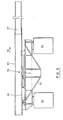
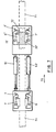
- FIGS 5 and 6 illustrate the inventive gripper 59, which is anchored to a cradle 62 with the aid of two hydraulic cylinders 60, 61 forming the stationary part of the gripper, the cradle resting on two supports 63, 64 such as girders resting on bridge columns.
- the gripper is to move a beam 65 in the direction of the arrow 66 towards a support not illustrated on the drawing, which is at a distance corresponding to the length of the beam 65 from the support 64.
- the width and depth of the beam changes at a portion 67.
- the inventive gripper 59 performs a forward advancing movement of the beam 65 by the hydraulic cylinders 60, 61 thrusting out their rams 68, 69 with the aid of unillustrated conventional means, the rams being pivotably mounted in the lugs 2, 3 of the base plate 1.
- the other ends of the hydraulic cylinders are anchored on the stationary cradle 62.
- the base plate 1 is moved by the thrusting movement from the position illustrated in Figure 6 by full lines to the one illustrated by dashed lines.
- the jaws 19, 20 are forced against the lower flange on the beam 65 as the result of the sloping guide surfaces 17, 18 until the engagement is sufficiently strong for the beam finally to accompany the movement of the base plate 1.
- the amount of movement is dependent on the stroke of the hydraulic cylinders and may be about 25 mm.
- the jaws relinquish their grip on the lower flange and move relative the rockers 6, 7 against the bias of the compression springs 30, 31 until they abut against the set screws 38, 39, which have been pre-set so that their is no risk of the guide rods 24, 25 becoming damaged.
- the serrations 21, 22 glide along the beam. If the load has a section which is conical, e.g.
- the jaws will turn during the withdrawal movement of the hydraulic cylinders and orient themselves such that their serrations 21, 22 engage against the conical section. It is also clear that if the section of the load is such that one edge is straight while the other is inclined towards it, then only one of the two rockers 6, 7 will pivot.
- Figures 5 and 6 illustrate movement of a load by a gripper with a fixed anchorage. It is also possible directly to attach the gripper to the load such as to move both gripper and load, either horizontally or vertically.
- a gripper arrangement with these properties is obtained by conventionally arranging two gripper base plates and their details in tandem and with hydraulic cylinders 60 and 61 between them, as illustrated in Figure 7.
- the units comprising base plate 1 with details, 60 and 61 are in accordance with those already illustrated, and an additional unit 1' corresponding to the gripper illustrated in Figure 1 is connected to the hydraulic cylinders.
- the serrations in the first-mentioned unit face the same way as the serrations in the additional unit 1'.
- tandem-connected gripping arrangement is controlled to move in the direction of the arrow 70 such that when the hydraulic cylinders thrust, the jaws 19', 20' in the unit 1' glide along the tractional bar 71, schematically illustrated by dashed lines in the Figure, while the jaws in the first-mentioned unit are in firm engagement with the tractional bar.
- the hydraulic cylinders 60, 61 then draw in their rams, whereon the jaws in the first-mentioned unit relinquish their grip, while the jaws in the unit 1' maintain a firm engagement with the tractional bar 71.
- the tandem arrangement illustrated in Figure 7 is used for moving loads horizontally, the load is suitably placed on the unit 1'.
- a slab of Teflon 72 is suitably placed between the base plate and the fractional bar 71 as a friction- decreasing means.
- the unit 1' carrying the load will then serve as a bearing between the load and tractional bar.
- the tandem-connected arrangement illustrated in Figure 7 can also climb vertically along a tractional bar, rail, beam or other unit while lifting the load below it.
- each of the rockers in the inventive gripper is mounted on a pivot pin, and since there is no other mechanical link between the rockers, these can pivot in mutual independence in the manner illustrated in Figures 8-11.
- Figure 8 it is illustrated in Figure 8 how both rockers may incline to the chain-dotted center line C of the base plate when advancing a beam, the width of which changes in the manner illustrated by dashed lines in the Figure.
- Figure 9 illustrates how the left-hand jaw housing by itself is at an angle to the center line C, while the righthand housing is parallel to the center line when advancing a beam, the width of which changes in the manner illustrated by dashed lines in the Figure.
- Figure 10 illustrates how both jaw housings are inclined in the same direction relative the center line C in advancing a beam which forms an angle to the center line C of the base plate.
- Figure 11 illustrates the case occurring when the two hydraulic cylinders do not move the same distance during an advancing movement of the gripper, the base plate being on the skew but the housings turning relative the base plate while retaining their engagement with the load as it is advanced.
- the base plate 1 may be exchanged for a base plate having a distance between the pivot pins 9, 10 appropriate to the width of the object to be gripped.
Landscapes
- Structural Engineering (AREA)
- Fluid Mechanics (AREA)
- Life Sciences & Earth Sciences (AREA)
- Engineering & Computer Science (AREA)
- Geology (AREA)
- Mechanical Engineering (AREA)
- Physics & Mathematics (AREA)
- Load-Engaging Elements For Cranes (AREA)
- Conveying And Assembling Of Building Elements In Situ (AREA)
- Control And Other Processes For Unpacking Of Materials (AREA)
- Specific Conveyance Elements (AREA)
- Jib Cranes (AREA)
- Manipulator (AREA)
Claims (5)
Priority Applications (1)
| Application Number | Priority Date | Filing Date | Title |
|---|---|---|---|
| AT84850356T ATE27256T1 (de) | 1983-11-25 | 1984-11-14 | Greifvorrichtung fuer antriebsausruestung. |
Applications Claiming Priority (2)
| Application Number | Priority Date | Filing Date | Title |
|---|---|---|---|
| SE8306533 | 1983-11-25 | ||
| SE8306533A SE449608B (sv) | 1983-11-25 | 1983-11-25 | Griporgan for forflyttning av tunga laster |
Publications (2)
| Publication Number | Publication Date |
|---|---|
| EP0157073A1 EP0157073A1 (fr) | 1985-10-09 |
| EP0157073B1 true EP0157073B1 (fr) | 1987-05-20 |
Family
ID=20353473
Family Applications (1)
| Application Number | Title | Priority Date | Filing Date |
|---|---|---|---|
| EP84850356A Expired EP0157073B1 (fr) | 1983-11-25 | 1984-11-14 | Organe de préhension pour vérin |
Country Status (5)
| Country | Link |
|---|---|
| EP (1) | EP0157073B1 (fr) |
| AT (1) | ATE27256T1 (fr) |
| DE (1) | DE3463752D1 (fr) |
| NO (1) | NO159526C (fr) |
| SE (1) | SE449608B (fr) |
Families Citing this family (2)
| Publication number | Priority date | Publication date | Assignee | Title |
|---|---|---|---|---|
| US4961562A (en) * | 1988-11-16 | 1990-10-09 | Donnally Robert B | Apparatus for engaging beams |
| ES2399789B1 (es) * | 2011-02-02 | 2014-06-03 | German Rodriguez Martin | Dispositivo trepador para elevacion o desplazamiento de grandes cargas |
Family Cites Families (6)
| Publication number | Priority date | Publication date | Assignee | Title |
|---|---|---|---|---|
| US3203669A (en) * | 1961-05-17 | 1965-08-31 | Byggforbattring Ab | Climbing jack |
| CH440617A (de) * | 1965-04-28 | 1967-07-31 | Werkzeugfabrik Selzach Ag | Antriebsausrüstung |
| DE2314025C2 (de) * | 1973-03-21 | 1985-01-17 | Bernhard 5038 Hahnwald Ahl | Gerät zum Heben gleitender Formen an Stahlstangen zur Herstellung von Betonbauwerken nach dem Gleitschalungssystem |
| SE391171B (sv) * | 1975-11-11 | 1977-02-07 | Hoglund Ab Kasper | Anordning vid lastoverforingsaggregat |
| GB1548897A (en) * | 1976-05-06 | 1979-07-18 | Redpath Dorman Long Ltd | Movement of bridge spans or the like |
| US4277052A (en) * | 1979-08-17 | 1981-07-07 | Franz Kallinger | Jacking apparatus |
-
1983
- 1983-11-25 SE SE8306533A patent/SE449608B/sv not_active IP Right Cessation
-
1984
- 1984-11-14 AT AT84850356T patent/ATE27256T1/de not_active IP Right Cessation
- 1984-11-14 EP EP84850356A patent/EP0157073B1/fr not_active Expired
- 1984-11-14 DE DE8484850356T patent/DE3463752D1/de not_active Expired
- 1984-11-23 NO NO844684A patent/NO159526C/no unknown
Also Published As
| Publication number | Publication date |
|---|---|
| NO159526B (no) | 1988-10-03 |
| DE3463752D1 (en) | 1987-06-25 |
| SE8306533D0 (sv) | 1983-11-25 |
| EP0157073A1 (fr) | 1985-10-09 |
| SE8306533L (sv) | 1985-05-26 |
| NO844684L (no) | 1985-05-28 |
| ATE27256T1 (de) | 1987-06-15 |
| SE449608B (sv) | 1987-05-11 |
| NO159526C (no) | 1989-01-11 |
Similar Documents
| Publication | Publication Date | Title |
|---|---|---|
| EP0314854B1 (fr) | Machine de bourrage, de nivellement et de dressage de voie ferrée pour le nivellement et/ou le déplacement latéral d'une voie ferrée dans la zone d'une aiguille et d'un croisement | |
| US3807532A (en) | Self-energizing rail clamp | |
| US4176777A (en) | Setting arrangement for alignment and gap between two rail ends | |
| US4641818A (en) | Apparatus for adjusting two butt-ends of rails to be connected by welding | |
| JP4861892B2 (ja) | 遊間拡幅調整装置及びその遊間拡幅調整装置に用いる遊間拡幅調整用ジャッキ | |
| CN115092825A (zh) | 一种新型桥面起吊装置及使用方法 | |
| EP0157073B1 (fr) | Organe de préhension pour vérin | |
| FI69414C (fi) | Anordning foer fastsaettning av ett saxakaer i en gradsax | |
| US3949586A (en) | Rolling mill frame, in particular a universal rolling mill frame | |
| US4601141A (en) | Building structure expansion apparatus | |
| JPH0346210B2 (fr) | ||
| KR20190088328A (ko) | 롤러형 레일 클램핑 제동장치 | |
| US3991969A (en) | Form positioning apparatus | |
| CN215626212U (zh) | 一种箱梁吊具 | |
| EP0104164A1 (fr) | Procede et appareil de redressage d'un element deforme du chassis de la carrosserie d'un vehicule | |
| JPH08184294A (ja) | 管推進装置 | |
| CN111663578B (zh) | 一种预应力基桩高应变检测装置 | |
| US4189256A (en) | Pile guides | |
| CN220747233U (zh) | 一种可快速安装的钢结构厂房 | |
| CN113356039A (zh) | 一种可以快速便捷更换的桥梁支座 | |
| KR0116807Y1 (ko) | 연속주조기 세그먼트 제로장치의 롤러 정렬조정장치 | |
| CN220649957U (zh) | 一种混凝土梁桥静载试验检测机构 | |
| CN223269030U (zh) | 伸缩缝过桥板 | |
| US3638909A (en) | Gripping means | |
| CN213232989U (zh) | 铁路工务钢轨跨线装置 |
Legal Events
| Date | Code | Title | Description |
|---|---|---|---|
| PUAI | Public reference made under article 153(3) epc to a published international application that has entered the european phase |
Free format text: ORIGINAL CODE: 0009012 |
|
| AK | Designated contracting states |
Designated state(s): AT CH DE GB LI NL |
|
| 17P | Request for examination filed |
Effective date: 19850911 |
|
| 17Q | First examination report despatched |
Effective date: 19860318 |
|
| GRAA | (expected) grant |
Free format text: ORIGINAL CODE: 0009210 |
|
| AK | Designated contracting states |
Kind code of ref document: B1 Designated state(s): AT CH DE GB LI NL |
|
| REF | Corresponds to: |
Ref document number: 27256 Country of ref document: AT Date of ref document: 19870615 Kind code of ref document: T |
|
| REF | Corresponds to: |
Ref document number: 3463752 Country of ref document: DE Date of ref document: 19870625 |
|
| PLBE | No opposition filed within time limit |
Free format text: ORIGINAL CODE: 0009261 |
|
| STAA | Information on the status of an ep patent application or granted ep patent |
Free format text: STATUS: NO OPPOSITION FILED WITHIN TIME LIMIT |
|
| 26N | No opposition filed | ||
| PGFP | Annual fee paid to national office [announced via postgrant information from national office to epo] |
Ref country code: GB Payment date: 19911113 Year of fee payment: 8 |
|
| PGFP | Annual fee paid to national office [announced via postgrant information from national office to epo] |
Ref country code: DE Payment date: 19911114 Year of fee payment: 8 |
|
| PGFP | Annual fee paid to national office [announced via postgrant information from national office to epo] |
Ref country code: CH Payment date: 19911128 Year of fee payment: 8 |
|
| PGFP | Annual fee paid to national office [announced via postgrant information from national office to epo] |
Ref country code: AT Payment date: 19911129 Year of fee payment: 8 |
|
| PGFP | Annual fee paid to national office [announced via postgrant information from national office to epo] |
Ref country code: NL Payment date: 19911130 Year of fee payment: 8 |
|
| PG25 | Lapsed in a contracting state [announced via postgrant information from national office to epo] |
Ref country code: GB Effective date: 19921114 Ref country code: AT Effective date: 19921114 |
|
| PG25 | Lapsed in a contracting state [announced via postgrant information from national office to epo] |
Ref country code: LI Effective date: 19921130 Ref country code: CH Effective date: 19921130 |
|
| PG25 | Lapsed in a contracting state [announced via postgrant information from national office to epo] |
Ref country code: NL Effective date: 19930601 |
|
| GBPC | Gb: european patent ceased through non-payment of renewal fee |
Effective date: 19921114 |
|
| NLV4 | Nl: lapsed or anulled due to non-payment of the annual fee | ||
| REG | Reference to a national code |
Ref country code: CH Ref legal event code: PL |
|
| PG25 | Lapsed in a contracting state [announced via postgrant information from national office to epo] |
Ref country code: DE Effective date: 19930803 |