EP0157091A2 - Soutien de talon - Google Patents
Soutien de talon Download PDFInfo
- Publication number
- EP0157091A2 EP0157091A2 EP85100664A EP85100664A EP0157091A2 EP 0157091 A2 EP0157091 A2 EP 0157091A2 EP 85100664 A EP85100664 A EP 85100664A EP 85100664 A EP85100664 A EP 85100664A EP 0157091 A2 EP0157091 A2 EP 0157091A2
- Authority
- EP
- European Patent Office
- Prior art keywords
- heel holder
- lever
- release lever
- binding housing
- control
- Prior art date
- Legal status (The legal status is an assumption and is not a legal conclusion. Google has not performed a legal analysis and makes no representation as to the accuracy of the status listed.)
- Granted
Links
Images




Classifications
-
- A—HUMAN NECESSITIES
- A63—SPORTS; GAMES; AMUSEMENTS
- A63C—SKATES; SKIS; ROLLER SKATES; DESIGN OR LAYOUT OF COURTS, RINKS OR THE LIKE
- A63C9/00—Ski bindings
- A63C9/08—Ski bindings yieldable or self-releasing in the event of an accident, i.e. safety bindings
- A63C9/084—Ski bindings yieldable or self-releasing in the event of an accident, i.e. safety bindings with heel hold-downs, e.g. swingable
- A63C9/0847—Details of the manual release
-
- A—HUMAN NECESSITIES
- A63—SPORTS; GAMES; AMUSEMENTS
- A63C—SKATES; SKIS; ROLLER SKATES; DESIGN OR LAYOUT OF COURTS, RINKS OR THE LIKE
- A63C9/00—Ski bindings
- A63C9/08—Ski bindings yieldable or self-releasing in the event of an accident, i.e. safety bindings
-
- A—HUMAN NECESSITIES
- A63—SPORTS; GAMES; AMUSEMENTS
- A63C—SKATES; SKIS; ROLLER SKATES; DESIGN OR LAYOUT OF COURTS, RINKS OR THE LIKE
- A63C9/00—Ski bindings
- A63C9/08—Ski bindings yieldable or self-releasing in the event of an accident, i.e. safety bindings
- A63C9/084—Ski bindings yieldable or self-releasing in the event of an accident, i.e. safety bindings with heel hold-downs, e.g. swingable
- A63C9/0841—Ski bindings yieldable or self-releasing in the event of an accident, i.e. safety bindings with heel hold-downs, e.g. swingable with a single jaw
- A63C9/0842—Ski bindings yieldable or self-releasing in the event of an accident, i.e. safety bindings with heel hold-downs, e.g. swingable with a single jaw the jaw pivoting on the body or base about a transverse axis
-
- A—HUMAN NECESSITIES
- A63—SPORTS; GAMES; AMUSEMENTS
- A63C—SKATES; SKIS; ROLLER SKATES; DESIGN OR LAYOUT OF COURTS, RINKS OR THE LIKE
- A63C9/00—Ski bindings
- A63C9/08—Ski bindings yieldable or self-releasing in the event of an accident, i.e. safety bindings
- A63C9/084—Ski bindings yieldable or self-releasing in the event of an accident, i.e. safety bindings with heel hold-downs, e.g. swingable
- A63C9/0846—Details of the release or step-in mechanism
-
- A—HUMAN NECESSITIES
- A63—SPORTS; GAMES; AMUSEMENTS
- A63C—SKATES; SKIS; ROLLER SKATES; DESIGN OR LAYOUT OF COURTS, RINKS OR THE LIKE
- A63C9/00—Ski bindings
- A63C9/08—Ski bindings yieldable or self-releasing in the event of an accident, i.e. safety bindings
- A63C9/0805—Adjustment of the toe or heel holders; Indicators therefor
Definitions
- the invention relates to a heel holder with a bearing block in which a binding housing, which is under the influence of an opening spring and carries a hold-down device and a step spur at its end facing the ski shoe, and a control lever which is acted upon by a detent spring which is adjustable in its pretension is mounted on two transverse axes arranged at a distance from one another in the longitudinal direction of the ski, a side of the control lever facing the ski shoe being assigned a control element which is held in place by a release lever in the driving position of the heel holder.
- control element is designed as a bolt which is finally guided in circular guides of the bearing block, in circular slots of the housing which are open towards the bottom, and finally in angled guide slots of a slide.
- This construction has the disadvantage that a relatively large friction of the control element occurs on the release lever at the beginning of the arbitrary release, especially since the control element is loaded by the full pressure of the detent spring.
- the structure of the known heel holder is relatively complicated.
- the invention has as its object to eliminate these disadvantages and to provide a heel holder of the type mentioned, in which the A r-finishing operation is a deliberate tripping substantially reduced.
- this object is achieved by two different constructions.
- One construction is characterized in particular by the fact that the control element is designed as a crankshaft, which is mounted in the region of the binding housing which is adjacent to the base of the bearing block and lies under the control lever, and the crank of which is intended to rest on the control lever.
- the control member is a control pin
- the release lever is mounted in the bearing block on the axis for the binding housing and its two legs, which are known per se and have hook-shaped projections, are arranged within the side walls of the bearing block.
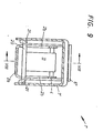
- FIG. 7 the position of the heel holder in the driving position is shown in FIG. 7 immediately before the arbitrary release, that is to say with the release lever already depressed.
- FIG. 8 shows a third exemplary embodiment in section along the line VIII-VIII in FIG. 9.
- FIG. 9 shows a section along the line IX-IX in FIG. 8.
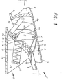
- the heel holder shown in FIGS. 1-3 is designated 1 in its entirety. It has an approximately U-shaped bearing block 2 in cross section, the base 2a of which can be displaced and locked in guide rails (not shown) on the top of a ski (not shown).
- Two axes 3 and 4 are mounted in the two side walls 2b of the bearing block 2.
- the axis serves from these 3 as an axis for two articulated brackets 5, a release lever 6 which is approximately U-shaped in plan view and a binding housing 7 which carries a hold-down device 8 and a step spur 9 on its front wall facing the ski boot.
- the binding housing 7 is connected to the joint plates 5 via two further joint plates 10. Furthermore, there is at least one leg spring 7a acting as an opening spring on the axis 3.
- a control lever 11 is pivotally mounted. Furthermore, it is between the two side walls 2b of the bearing bracket 2, a shaped U-plan view of the spring housing 12, which houses 13, a detent spring is fixed, which b in a e-known per can be adjusted in the drawing, but not shown, in its bias .
- the detent spring 13 presses on the control lever 11 via a spring plate 14 which is adjustable in the longitudinal direction in the spring housing 12 and which is guided in known manner in oblong holes in the legs of the spring housing 12.
- the two link plates 5 have elongated holes 5a, which are provided by a bolt 15 are enforced, which is under the influence of two tension springs 16, which try to pull it against the axis 3.
- the trigger lever 6 is designed with two arms and angled somewhat in the region of its axis of rotation. On its load arm, the release lever 6 carries a hook-shaped projection 6a, which holds the bolt in the driving position of the heel holder 1.
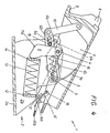
- the heels are in the driving position holder 1 in the position shown in Figure 1. If the heel holder is subjected to an involuntary release, the bolt 15 slides along the control surface 11a of the control lever 11; the spring plate 14 is pressed back against the force of the detent spring 13, and this is tensioned. As soon as the trigger point is exceeded, the leg spring 7a seated on the axis 3 pivots the binding housing 7 into the entry position (see FIG. 3). This pivoting movement is somewhat supported by the detent spring 13.
- the release lever 6 is pivoted clockwise against the force of the spring 6c.
- the projection 6a on each leg of the release lever 6 releases the bolt 15, which can now be moved in the two elongated holes 5a against the force of the two tension springs 16 towards the ski boot. Since the two tension springs 16 are relatively weak, relatively little effort is required to pivot the heel holder 1 into the open position of the heel holder 1, which is brought about by the leg spring 7a seated on the axis 3.
- the release lever 6 can be pivoted counterclockwise by the leg spring 6c, the projection 6a engaging behind the bolt 15 again (see FIG. 3). The skier can now step into the heel holder 1 again with the ski boot.
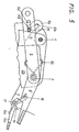
- This heel holder 1 also has a bearing block 2 which is approximately U-shaped in cross section available, the base 2a of which is displaceable and lockable in guide rails, not shown, on the top of a ski, not shown.
- Two axes 3 and 4 are mounted in the two side walls 2b of the bearing block 2.
- the axis 3 serves as a pivot axis for two hinge straps 5, a release lever 6 ′ which is approximately U-shaped in plan view and a binding housing 7 which carries a hold-down device 8 and a step spur 9 on its front wall facing the ski boot.
- the binding housing 7 is connected to the joint plates 5 via two further joint plates 10.
- a control lever 11 is pivotally mounted on the other axis 4. Furthermore, between the two side walls 2b of the bearing block 2 there is a U-shaped spring housing 12 in plan view, in which a detent spring 13 is accommodated, which can be adjusted in its pretension in a manner known per se, but not shown in the drawing.
- the detent spring 13 presses on the control lever 11 via a spring plate 14 which is adjustable in the longitudinal direction in the spring housing 12 and which is guided in known manner in elongated holes in ia legs of the spring housing 12.
- the two link plates 5 have elongated holes 5a, which are provided by a bolt 15 are enforced, which is under the influence of two tension springs 16, which try to pull it against the axis 3.
- the trigger lever 6 ' has two arms and is angled somewhat in the region of its axis of rotation. On its load arm, the trigger lever 6 'carries a hook-shaped projection 6'a, which holds the bolt 15 in the driving position of the heel holder 1'.
- the hook-shaped projection 6! A carries a flat surface 6'd, which in the driving position of the heel holder 1 'runs perpendicular to the axis of the elongated holes 5a of the two joint plates 5.
- This surface 6 'd is followed by a guide 6'b, which is open on one side and is inclined with respect to the axis of the elongated holes 5a, in which the pin 15 is guided to the end of the guide when the skier with his ski shoe in the heel holder 1' with a reduced Wants to get in.
- the release lever 6 ' is under the influence of a leg spring 6'c, which tries to pivot it counterclockwise and the other end of which is anchored to the one joint plate 5.
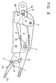
- a two-armed auxiliary lever 16b is pivotably mounted on an axis 17 at the lower end.
- This lever 16b is also under the influence of a leg spring 16a, which tends to pivot the auxiliary lever 16b counterclockwise.
- the other end of the leg spring 16a rests on a bolt 18 which is arranged in the force arm of the release lever 6 'in the transverse direction.
- This bolt 18 also serves to fix the release lever 6 ′ relative to the binding housing 7 by means of the auxiliary lever 16b.
- a Binding housing 7 arranged stop designated, which limits the pivot angle of the auxiliary lever 16b counterclockwise.
- the heel holder 1 In the driving position, the heel holder 1 'is in the position shown in FIG. 7. If the heel holder is subjected to an involuntary release, the bolt 15 slides along the control surface 11a of the control lever 11; the spring plate 14 is pressed back against the force of the detent spring 13, and this is tensioned. As soon as the trigger point is exceeded, the leg spring 7a seated on the axis 3 pivots the binding housing 7 into the entry position (see FIG. 4). This pivoting movement is somewhat supported by the detent spring 13.
- the release lever 6' is pivoted counterclockwise against the force of the spring 6 '.
- the surface 6 ' dan releases each leg of the release lever 6 the bolt 15, which can now be moved in the two elongated holes 5a against the force of the two tension springs 16 towards the ski boot. Since the two tension springs 16 are relatively weak, a relatively small amount of force is required to pivot the heel holder 1 'into the open position of the heel holder 1', which is brought about by the leg spring 7a seated on the axis 3.
- the auxiliary lever 16b is pivoted clockwise by the skier against the force of the leg spring 16a.
- the auxiliary lever 16 thereby releases the pin 18 on the release lever 6 ', which is under the influence of the leg spring 6'c.
- the bolt 15 arrives in the guides 6'b, the effective lengths of which are somewhat shorter than the length of the two elongated holes 5a in the link plates 5.
- the detent spring 16 When the hold-down device 8 is depressed with the help of the ski boot of the skier, the detent spring 16 is therefore somewhat compressed, but the path of the spring plate 14 required for boarding is considerably reduced compared to the path during normal boarding, so that the work to be done when boarding is considerably reduced is set.
- FIGS. 8 and 9 A somewhat modified exemplary embodiment is shown in FIGS. 8 and 9.
- the exemplary embodiment of a heel holder 1 ′′ shown in these figures has a bearing block 2 which is approximately U-shaped in cross section and has a base 2a and two side walls 2 ′.
- the two side walls 2 ′ b carry on the side facing the ski shoe from the top of the bearing block Lugs 2'd running obliquely downwards towards the ski boot.
- Two axles 3 and 4 are mounted in the two side walls 2 '.
- the axle 3 serves as a pivot axis for a binding housing 7' which has a hold-down device 8 on its side facing the ski boot and carries a step spur 9.
- a leg spring 7'a designed as an opening spring is arranged on the axis 3.
- a control lever 11 is in turn pivotally mounted on the axis 4. Furthermore, the bearing block 2 'receives a detent spring 13 which extends in the longitudinal direction the spring-displaceable spring plate 14 rests on the side of the control lever 11 facing away from the ski boot 11.
- the spring plate 14 has lateral projections which are not shown in FIGS set elongated holes in the side walls 2'b of the bearing block 2 'are guided in a known manner.
- the locking spring 13 is adjustable in its known in its manner in its bias.
- crankshaft 20 Under the control lever 11 is a crankshaft 20 which abuts the control lever 11 with its crank and which has both ends in the side walls of the binding housing 7 ' device.
- the two side walls 2b of the bearing block 2 have a cutout 2c in the region of the crankshaft 20, which enables the crankshaft to be rotated by 90 °.
- U-shaped trigger lever 6 " designed as an angle lever, is pivotally mounted on semi-axles 21.
- the load arm of the trigger lever 6" carries a hook-shaped projection 6 "a, which serves to hold the crankshaft 20 in that position, in which the crankshaft touches the control surface 11a.
- the heel holder 1 " In the driving position, the heel holder 1 "is in the position shown in FIG. 8. If the heel holder 1" is involuntarily released while the skier is traveling, the binding housing 7 'pivots clockwise about the axis 3. The control lever 11 is pivoted counterclockwise, and the detent spring 13 is tensioned. After the crank of the crankshaft 20 has passed the trigger point on the control lever 11, the binding housing 7 'is pivoted into the entry position under the influence of the leg spring 7'a surrounding the axis 3. The trigger lever 6 ", which is mounted here between the bearing block 2 and the binding housing, takes part in this pivoting movement.
- crankshaft 20 comes out of contact with the control lever 11 and the binding housing 7 'can move under the influence of the leg spring 7'a into the entry position, but before the end position is reached, the crank of the crankshaft 20 comes into contact with the two lugs 2d of the side walls 2b of the bearing block 2.
- This contact causes the crankshaft 20 to pivot clockwise by 90 °.
- the release lever 6 can be pivoted counterclockwise back to its original position, in which it engages behind the crank of the crankshaft 20 with its hook-shaped projection 6" a. Now the skier can put the ski boot into the heel holder 1 " get in and swivel it into the driving position.
- the detent spring in the last exemplary embodiment does not have to be arranged directly in the bearing block, but rather can also be accommodated here in a U-shaped spring housing in plan view, which is rigidly fastened in the bearing block and which carries the elongated holes for guiding the displaceable spring plate resting on the control lever .
Landscapes
- Footwear And Its Accessory, Manufacturing Method And Apparatuses (AREA)
Applications Claiming Priority (4)
| Application Number | Priority Date | Filing Date | Title |
|---|---|---|---|
| AT0042484A AT380640B (de) | 1984-02-10 | 1984-02-10 | Fersenhalter |
| AT424/84 | 1984-02-10 | ||
| AT74784A AT384747B (de) | 1984-03-06 | 1984-03-06 | Fersenhalter |
| AT747/84 | 1984-03-06 |
Publications (3)
| Publication Number | Publication Date |
|---|---|
| EP0157091A2 true EP0157091A2 (fr) | 1985-10-09 |
| EP0157091A3 EP0157091A3 (en) | 1987-03-25 |
| EP0157091B1 EP0157091B1 (fr) | 1990-03-14 |
Family
ID=25592698
Family Applications (1)
| Application Number | Title | Priority Date | Filing Date |
|---|---|---|---|
| EP85100664A Expired - Lifetime EP0157091B1 (fr) | 1984-02-10 | 1985-01-23 | Soutien de talon |
Country Status (3)
| Country | Link |
|---|---|
| US (1) | US4664406A (fr) |
| EP (1) | EP0157091B1 (fr) |
| DE (1) | DE3576462D1 (fr) |
Families Citing this family (4)
| Publication number | Priority date | Publication date | Assignee | Title |
|---|---|---|---|---|
| US5690351A (en) | 1995-07-21 | 1997-11-25 | Karol; Chris | Snowboard binding system |
| US6053524A (en) * | 1997-01-08 | 2000-04-25 | The Burton Corporation | Method and apparatus for indicating when a snowboard binding is locked |
| IT1298824B1 (it) * | 1998-03-27 | 2000-02-02 | Htm Sport Spa | Struttura di leva,particolarmente per calzature sportive |
| US20100298507A1 (en) | 2009-05-19 | 2010-11-25 | Menschig Klaus R | Polyisobutylene Production Process With Improved Efficiencies And/Or For Forming Products Having Improved Characteristics And Polyisobutylene Products Produced Thereby |
Family Cites Families (11)
| Publication number | Priority date | Publication date | Assignee | Title |
|---|---|---|---|---|
| CH500730A (fr) * | 1965-07-15 | 1970-12-31 | Reuge Sa | Fixation de ski de sécurité |
| FR1521946A (fr) * | 1966-05-06 | 1968-04-19 | Dispositif d'attache pour fixations de ski de sécurité | |
| US3580597A (en) * | 1968-03-22 | 1971-05-25 | Jean Joseph Alfred Beyl | Heel downholder for safety ski bindings |
| AT296839B (de) * | 1970-02-03 | 1972-02-25 | Smolka & Co Wiener Metall | Auslösebindung |
| AT341393B (de) * | 1975-12-19 | 1978-02-10 | Smolka & Co Wiener Metall | Auslosebindung |
| DE3033021A1 (de) * | 1980-09-02 | 1982-04-29 | Marker, Hannes, 8100 Garmisch-Partenkirchen | Fersenhalter einer sicherheits-skibindung |
| DE3033568A1 (de) * | 1980-09-05 | 1982-05-06 | Marker, Hannes, 8100 Garmisch-Partenkirchen | Fersenhalter einer sicherheits-skibindung |
| DE3105294A1 (de) * | 1981-02-13 | 1982-09-09 | Hannes Marker Sicherheits-Skibindungen GmbH & Co KG, 8100 Garmisch-Partenkirchen | Fersenhalter einer sicherheits-skibindung |
| FR2506171B1 (fr) * | 1981-05-22 | 1985-05-31 | Look Sa | Dispositif de verrouillage pour fixation de ski |
| AT371353B (de) * | 1981-09-25 | 1983-06-27 | Tyrolia Freizeitgeraete | Fersenhalter |
| EP0117464B1 (fr) * | 1983-02-16 | 1986-06-04 | Tmc Corporation | Fixation de ski de sécurité |
-
1985
- 1985-01-23 DE DE8585100664T patent/DE3576462D1/de not_active Expired - Lifetime
- 1985-01-23 EP EP85100664A patent/EP0157091B1/fr not_active Expired - Lifetime
- 1985-02-11 US US06/700,260 patent/US4664406A/en not_active Expired - Fee Related
Also Published As
| Publication number | Publication date |
|---|---|
| EP0157091A3 (en) | 1987-03-25 |
| EP0157091B1 (fr) | 1990-03-14 |
| US4664406A (en) | 1987-05-12 |
| DE3576462D1 (de) | 1990-04-19 |
Similar Documents
| Publication | Publication Date | Title |
|---|---|---|
| DE9421380U1 (de) | Snowboardbindung | |
| DE2739207A1 (de) | Skistiefelelement | |
| EP0778055A2 (fr) | Fixation pour snowboard ou similaire | |
| EP2695647B1 (fr) | Frein pour ski avec verrouillage | |
| DE2218478C3 (de) | Auslösender Fersenniederhalter für Skibindungen | |
| DE2926822A1 (de) | Bindungsanordnung fuer ski | |
| EP0247104B1 (fr) | Fixation de ski pour ski de fond ou de tourisme | |
| DE3143576A1 (de) | Backen, insbesondere vorderbacken, fuer sicherheitsskibindungen | |
| EP0264436B1 (fr) | Fixation de securite pour skis, en particulier fixation du talon | |
| DE2604656A1 (de) | Vorrichtung zum automatischen anhalten eines vom skilaeufer geloesten skis | |
| EP0410290B1 (fr) | Fixation de sécurité pour planche de glisse, notamment pour surf de neige | |
| EP0157091A2 (fr) | Soutien de talon | |
| CH646340A5 (de) | Sicherheitsskibindung. | |
| DE69201889T2 (de) | Sicherheitsskibindung. | |
| DE3445760A1 (de) | Ausloeseskibindung | |
| CH653560A5 (de) | Mit einer skibremse kombinierter fersenhalter. | |
| DE3204468C2 (fr) | ||
| EP0227939B1 (fr) | Frein pour ski | |
| EP0150028B1 (fr) | Butée arrière | |
| EP0394380A1 (fr) | Fixation de securite pour ski. | |
| EP0389757A1 (fr) | Butée avant | |
| WO1987007516A2 (fr) | Fixation de securite pour ski | |
| DE2621758C3 (de) | Sicherheits-Auslöseteil für Skibindungen | |
| EP0160308A2 (fr) | Rabattant de talon | |
| DE3043988A1 (de) | Sohlen- bzw. fersenhalter fuer skibindungen |
Legal Events
| Date | Code | Title | Description |
|---|---|---|---|
| PUAI | Public reference made under article 153(3) epc to a published international application that has entered the european phase |
Free format text: ORIGINAL CODE: 0009012 |
|
| AK | Designated contracting states |
Designated state(s): CH DE FR LI |
|
| PUAL | Search report despatched |
Free format text: ORIGINAL CODE: 0009013 |
|
| AK | Designated contracting states |
Kind code of ref document: A3 Designated state(s): CH DE FR LI |
|
| 17P | Request for examination filed |
Effective date: 19870220 |
|
| 17Q | First examination report despatched |
Effective date: 19880801 |
|
| GRAA | (expected) grant |
Free format text: ORIGINAL CODE: 0009210 |
|
| AK | Designated contracting states |
Kind code of ref document: B1 Designated state(s): CH DE FR LI |
|
| REF | Corresponds to: |
Ref document number: 3576462 Country of ref document: DE Date of ref document: 19900419 |
|
| ET | Fr: translation filed | ||
| PLBE | No opposition filed within time limit |
Free format text: ORIGINAL CODE: 0009261 |
|
| STAA | Information on the status of an ep patent application or granted ep patent |
Free format text: STATUS: NO OPPOSITION FILED WITHIN TIME LIMIT |
|
| PGFP | Annual fee paid to national office [announced via postgrant information from national office to epo] |
Ref country code: FR Payment date: 19910109 Year of fee payment: 7 |
|
| PGFP | Annual fee paid to national office [announced via postgrant information from national office to epo] |
Ref country code: DE Payment date: 19910115 Year of fee payment: 7 |
|
| 26N | No opposition filed | ||
| REG | Reference to a national code |
Ref country code: CH Ref legal event code: PUE Owner name: AMF CORPORATION TRANSFER- HTM SPORTS CORP. Ref country code: CH Ref legal event code: PFA Free format text: TMC CORPORATION, RUESSENSTRASSE 16, WALTERSWIL ZG, BAAR |
|
| PGFP | Annual fee paid to national office [announced via postgrant information from national office to epo] |
Ref country code: CH Payment date: 19920109 Year of fee payment: 8 |
|
| REG | Reference to a national code |
Ref country code: FR Ref legal event code: TP Ref country code: FR Ref legal event code: CD |
|
| PG25 | Lapsed in a contracting state [announced via postgrant information from national office to epo] |
Ref country code: FR Effective date: 19920930 |
|
| PG25 | Lapsed in a contracting state [announced via postgrant information from national office to epo] |
Ref country code: DE Effective date: 19921001 |
|
| REG | Reference to a national code |
Ref country code: FR Ref legal event code: ST |
|
| PG25 | Lapsed in a contracting state [announced via postgrant information from national office to epo] |
Ref country code: LI Effective date: 19930131 Ref country code: CH Effective date: 19930131 |
|
| REG | Reference to a national code |
Ref country code: CH Ref legal event code: PL |