EP0160308A2 - Rabattant de talon - Google Patents
Rabattant de talon Download PDFInfo
- Publication number
- EP0160308A2 EP0160308A2 EP85105346A EP85105346A EP0160308A2 EP 0160308 A2 EP0160308 A2 EP 0160308A2 EP 85105346 A EP85105346 A EP 85105346A EP 85105346 A EP85105346 A EP 85105346A EP 0160308 A2 EP0160308 A2 EP 0160308A2
- Authority
- EP
- European Patent Office
- Prior art keywords
- lever
- release lever
- projection
- binding housing
- pivot axis
- Prior art date
- Legal status (The legal status is an assumption and is not a legal conclusion. Google has not performed a legal analysis and makes no representation as to the accuracy of the status listed.)
- Granted
Links
Images


Classifications
-
- A—HUMAN NECESSITIES
- A63—SPORTS; GAMES; AMUSEMENTS
- A63C—SKATES; SKIS; ROLLER SKATES; DESIGN OR LAYOUT OF COURTS, RINKS OR THE LIKE
- A63C9/00—Ski bindings
- A63C9/08—Ski bindings yieldable or self-releasing in the event of an accident, i.e. safety bindings
- A63C9/084—Ski bindings yieldable or self-releasing in the event of an accident, i.e. safety bindings with heel hold-downs, e.g. swingable
- A63C9/0847—Details of the manual release
-
- A—HUMAN NECESSITIES
- A63—SPORTS; GAMES; AMUSEMENTS
- A63C—SKATES; SKIS; ROLLER SKATES; DESIGN OR LAYOUT OF COURTS, RINKS OR THE LIKE
- A63C9/00—Ski bindings
- A63C9/08—Ski bindings yieldable or self-releasing in the event of an accident, i.e. safety bindings
- A63C9/084—Ski bindings yieldable or self-releasing in the event of an accident, i.e. safety bindings with heel hold-downs, e.g. swingable
- A63C9/0841—Ski bindings yieldable or self-releasing in the event of an accident, i.e. safety bindings with heel hold-downs, e.g. swingable with a single jaw
- A63C9/0842—Ski bindings yieldable or self-releasing in the event of an accident, i.e. safety bindings with heel hold-downs, e.g. swingable with a single jaw the jaw pivoting on the body or base about a transverse axis
-
- A—HUMAN NECESSITIES
- A63—SPORTS; GAMES; AMUSEMENTS
- A63C—SKATES; SKIS; ROLLER SKATES; DESIGN OR LAYOUT OF COURTS, RINKS OR THE LIKE
- A63C9/00—Ski bindings
- A63C9/08—Ski bindings yieldable or self-releasing in the event of an accident, i.e. safety bindings
- A63C9/084—Ski bindings yieldable or self-releasing in the event of an accident, i.e. safety bindings with heel hold-downs, e.g. swingable
- A63C9/0846—Details of the release or step-in mechanism
Definitions
- the invention relates to a heel holder, as specified in the preamble of claim 1.
- Such a heel holder is described in FR-PS 1485706.
- the axis of the release lever is immovably arranged in the control lever. If the heel holder is opened arbitrarily, which is very common in practice and sometimes the release lever is carried out with the other ski by depressing it, damage to the control lever can occur as a result of the release force component acting in the direction of the longitudinal axis of the release lever.
- a version similar to the heel holder discussed at the outset is beachpieban in FR-PS 2 116 767.
- This version has a bearing block, in the upper area of which a pivot axis for a binding housing with hold-down device and step spur is arranged.
- a further pivot axis is provided for a two-part control lever which bears against a control element of the binding housing and is under the influence of a release spring which can be set in its pretension.
- the trigger faders are supported on the control lever by a U-shaped spring abutment, which is articulated with its two legs to the two parts of the control lever by means of semi-axles.
- the $ two semiaxes penetrate arc-shaped elongated holes in the side walls of the bearing block and carry the legs of a U-shaped, one-armed release lever at the protruding ends, which is supported on the approaches of the bearing block.
- This version has the main disadvantage that to open the heel holder. Skiers have to bend down because opening can only be done by pulling on a rope.
- the trigger spring is anchored, the other end of which is anchored to the pedestal is not only compressed, but also bent, which is an additional work and is perceived as unpleasant by weak skiers,
- the aim of the invention is to eliminate the disadvantages of the known constructions and to provide a heel holder which can be pressed. can be opened easily and in which no damage to the control lever can occur even if the user is very rough with the heel holder.
- this object is achieved according to the invention by the features of the characterizing part of this claim. This measure reliably keeps the control lever free from triggering forces,
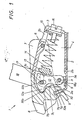
- FIG. 1 and 2 show vertical longitudinal central sections through a first embodiment in the driving position and in the open position.
- 3-5 show a second embodiment in the vertical longitudinal center section in the driving position, in the central position of the release lever, in which the control lever touches the release point, and in the end position of the release lever.
- the heel holder shown in FIGS. 1 and 2 is designated by 1 in its entirety. It has a base plate 2 which, at its end facing the ski boot, has a bend 2a which carries a control cam for lateral triggering.
- a base plate 2 which, at its end facing the ski boot, has a bend 2a which carries a control cam for lateral triggering.
- an approximately housing-shaped bearing block 3 is pivotally mounted on a vertical axis 4.
- This bracket 3 engages with an offset 3a arranged on its base in a slot 2b of the base plate 2 and is prevented from moving perpendicularly to the base plate by a cover plate 5 attached to the base plate. In this way, the bearing block 3 cannot be lifted off the base plate 2 at its end adjacent to the ski boot.
- a transverse pivot axis 6 is arranged, on which a binding housing 7, which is on its front. End holds a hold-down 8 and a step spur 9, is pivotally mounted.
- a binding housing 7 which is on its front. End holds a hold-down 8 and a step spur 9, is pivotally mounted.
- the front boundary wall of the binding housing 7 is one after Groove 7a which is open at the bottom and is rectangular in cross section, in which a roller 10 is mounted on an axis 10a, which roller is assigned to the control curve on the bend 2a of the base plate 2.
- the front boundary wall bears a control cam, which consists of an upper branch 7b and a lower branch 7c, which branches meet at the trigger point of the heel holder 1.
- a control lever 12 is pivotally mounted in the lower area of the side walls of the bearing block 3 on the side facing the ski boot.
- the control lever 12 has a nose 12a on its side facing the ski boot, which nose is intended to bear against the control curve 7b,? C.
- a groove running in the transverse direction, with a segmental or semicircular cross-section is recessed, in which a pressure piece 13 is pivotally mounted. This is from.
- a release spring 14 is applied, the other end of which is supported on a spring plate 15, which at the same time forms a pointer for the magnitude of the preload of the release spring and can be adjusted by means of an adjusting screw 16 in the direction of the axis of the release spring 14.
- the adjusting screw 16 is rotatable in the bearing block 3, but is secured against axial displacement.
- the pointer of the spring plate 15 is guided in a slot 3b of the bearing block 3 and in this way secures the spring plate 15 against rotation.
- the control lever 12 has an elongated hole 12b which runs approximately radially to its pivot axis 11, which is penetrated by an axis 17, which also passes through elongated holes 3c in the side walls of the bearing block 3 and on which a release lever 18 is fastened will.
- the release lever. 18 is — seen in the longitudinal direction of the ski — essentially U-shaped, the two legs mounted on the axis 17 being guided in slots in the binding housing running in the longitudinal direction of the ski.
- the end 18a of the load arm of each leg of the release lever 18 is approximately hook-shaped and engages under a projection 7d of the binding housing 7.
- the release lever 18 also carries another projection 18b, which in the driving position bears against the extension of the projection 7d of the binding housing 7. This defines the position of the release lever 18 in the closed position of the binding housing 7. In the open position. of the binding housing 7, however, the projection 7d of the binding housing bears against the projection 18b of the release lever 18. Since the trigger lever 18 on the one hand on the pivot axis 6 and on the other hand on that of the trigger. sefeder 14 acted upon control lever 12 is supported, the binding housing 7 is secured against further opening because, in order to bring about a further pivoting, the force of the release spring 14 would have to be overcome. Of course, the resistance to further opening of the binding housing increases as the set release force increases.
- the nose 12a of the control lever 12 initially slides over the upper branch 7b to the intersection of the two branches 7b, 7c, which de the trigger point de The nose 12a then moves along the lower branch 7c, this movement being supported by the release spring 14.
- the release lever 18 is pivoted clockwise.
- the binding housing 7 is raised by means of the end 18a of the load arm of the release lever 18 which engages under it until the lug 12a of the control lever 12 reaches the release point from has passed the two branches 7b and 7c formed control curve, then the heel holder 1 opens automatically under the influence of the release spring 14.
- the embodiment 1 'of a heel holder shown in FIGS. 3-5 is very similar to the first one. E s is different therefrom only in that the "binding housing 7 'does not carry one, but two projections 7'd and 7'e on each side, which project into the slots in which the leg of the release lever 18' in its pivoting movement
- the release lever 18 ' carries on each leg a projection 18'a which runs approximately perpendicular to its longitudinal axis and which comes to rest between the projections 7'd and 7'e of the binding housing 7'.
- the process in the involuntary triggering corresponds to that in the first embodiment.
- the upper projection 7'd lies on the upper side 18'b of the projection 18'a (see FIG. 3). If the release lever 18 'is now pivoted clockwise (see FIG. 4), the binding housing 7 'raised from the projection 18'a until the release point, ie the cut point of branches 7'b and 7'c of the control curve, has just been exceeded. From this point in time, the upper projection 7'd of the binding housing 7 'moves away from the upper side 18'b of the projection 18'a of the release lever 18', and the lower projection 7'e of the binding housing 7 'comes into contact with a cam 18 'd, which is formed by the release arm of the release lever 18'.
- this opening movement of the heel holder 1 ' is released by the release spring 14. supports. This movement ends when the trigger lever 18 'comes to rest on the pivot axis 6 of the binding housing 7'. However, since the pivoting movement of the binding housing 7 'continues under the influence of the release spring 14, the lower projection 7'e of the binding housing comes to rest against the underside 18' c of the projection 18'a of the release lever 18 '. The open position of the heel baller 1 'is thus reached (see FIG. 5).
Landscapes
- Footwear And Its Accessory, Manufacturing Method And Apparatuses (AREA)
- Fittings On The Vehicle Exterior For Carrying Loads, And Devices For Holding Or Mounting Articles (AREA)
- Acyclic And Carbocyclic Compounds In Medicinal Compositions (AREA)
- Pharmaceuticals Containing Other Organic And Inorganic Compounds (AREA)
Applications Claiming Priority (2)
| Application Number | Priority Date | Filing Date | Title |
|---|---|---|---|
| AT1480/84 | 1984-05-04 | ||
| AT0148084A AT379755B (de) | 1984-05-04 | 1984-05-04 | Fersenhalter |
Publications (3)
| Publication Number | Publication Date |
|---|---|
| EP0160308A2 true EP0160308A2 (fr) | 1985-11-06 |
| EP0160308A3 EP0160308A3 (en) | 1987-03-25 |
| EP0160308B1 EP0160308B1 (fr) | 1990-01-31 |
Family
ID=3514806
Family Applications (1)
| Application Number | Title | Priority Date | Filing Date |
|---|---|---|---|
| EP85105346A Expired - Lifetime EP0160308B1 (fr) | 1984-05-04 | 1985-05-02 | Rabattant de talon |
Country Status (5)
| Country | Link |
|---|---|
| US (1) | US4625991A (fr) |
| EP (1) | EP0160308B1 (fr) |
| JP (1) | JPS6116757A (fr) |
| AT (1) | AT379755B (fr) |
| DE (1) | DE3575675D1 (fr) |
Families Citing this family (6)
| Publication number | Priority date | Publication date | Assignee | Title |
|---|---|---|---|---|
| AT383749B (de) * | 1985-10-03 | 1987-08-10 | Tyrolia Freizeitgeraete | Sicherheitsskibindung |
| AT383960B (de) * | 1985-10-03 | 1987-09-10 | Tyrolia Freizeitgeraete | Sicherheitsskibindung |
| FR2669236B1 (fr) * | 1990-11-15 | 1993-01-22 | Salomon Sa | Fixation de securite de ski alpin. |
| FR2742061B1 (fr) * | 1995-12-08 | 1998-02-06 | Look Fixations Sa | Dispositif de retenue d'une chaussure a une planche de glisse telle qu'un ski ou similaire |
| US7318598B2 (en) * | 2003-02-18 | 2008-01-15 | Kneebinding Inc. | Alpine ski binding heel unit |
| FR2975604A1 (fr) * | 2011-05-27 | 2012-11-30 | Rossignol Sa | Talonniere de fixation de securite pour chaussure de ski |
Family Cites Families (14)
| Publication number | Priority date | Publication date | Assignee | Title |
|---|---|---|---|---|
| DE7147822U (de) * | 1975-02-13 | Axthammer L | Absatzhaltevorrichtung für Sicherheits-Skibindungen mit einem geschlossenen Gehäuse | |
| FR1485708A (fr) * | 1966-05-11 | 1967-06-23 | Applic Des Plastiques Et Produ | Attache de sécurité à enclenchement et déclenchement automatiques pour ski |
| FR2093056A5 (fr) * | 1970-06-01 | 1972-01-28 | Salomon Georges P J | |
| FR2116767A5 (fr) * | 1970-12-07 | 1972-07-21 | Carpano & Pons | |
| AT305843B (de) * | 1971-05-26 | 1973-03-12 | Smolka & Co Wiener Metall | Skibindung |
| AT327068B (de) * | 1973-10-04 | 1976-01-12 | Smolka & Co Wiener Metall | Sicherheitsskibindung |
| AT330630B (de) * | 1974-03-29 | 1976-07-12 | Smolka & Co Wiener Metall | Skibindung |
| FR2338060A1 (fr) * | 1976-01-16 | 1977-08-12 | Salomon & Fils F | Fixation de securite a dechaussage manuel |
| DE2628748A1 (de) * | 1976-06-25 | 1977-12-29 | Ver Baubeschlag Gretsch Co | Sicherheitsskibindung |
| AT358445B (de) * | 1978-01-05 | 1980-09-10 | Tyrolia Freizeitgeraete | Backen fuer sicherheitsskibindungen |
| JPS5848274U (ja) * | 1981-09-30 | 1983-04-01 | 株式会社マイルド | スキ−用ビンデイングのヒ−ルピ−ス |
| AT374698B (de) * | 1982-09-22 | 1984-05-25 | Tyrolia Freizeitgeraete | Fersenniederhalter |
| AT375267B (de) * | 1982-09-22 | 1984-07-25 | Tyrolia Freizeitgeraete | Fersenniederhalter |
| EP0118758B1 (fr) * | 1983-02-16 | 1986-05-28 | Tmc Corporation | Fixation de ski de sécurité |
-
1984
- 1984-05-04 AT AT0148084A patent/AT379755B/de not_active IP Right Cessation
-
1985
- 1985-04-26 US US06/727,703 patent/US4625991A/en not_active Expired - Fee Related
- 1985-05-02 JP JP60093991A patent/JPS6116757A/ja active Granted
- 1985-05-02 DE DE8585105346T patent/DE3575675D1/de not_active Expired - Lifetime
- 1985-05-02 EP EP85105346A patent/EP0160308B1/fr not_active Expired - Lifetime
Also Published As
| Publication number | Publication date |
|---|---|
| EP0160308A3 (en) | 1987-03-25 |
| DE3575675D1 (de) | 1990-03-08 |
| JPH0566156B2 (fr) | 1993-09-21 |
| JPS6116757A (ja) | 1986-01-24 |
| AT379755B (de) | 1986-02-25 |
| EP0160308B1 (fr) | 1990-01-31 |
| US4625991A (en) | 1986-12-02 |
| ATA148084A (de) | 1985-07-15 |
Similar Documents
| Publication | Publication Date | Title |
|---|---|---|
| EP0553468B1 (fr) | Fixation de securité pour ski | |
| DE4106401C2 (de) | Snowboard-Bindung | |
| DE1428987A1 (de) | Sicherheitsskibindung mit einer Absatzhaltevorrichtung | |
| DE2649826A1 (de) | Sicherheitsbindung zum halten eines schuhs auf einem ski | |
| DE2923281C2 (de) | Skibindungsteil | |
| EP0160308A2 (fr) | Rabattant de talon | |
| EP0098515B1 (fr) | Dispositif de réglage en longueur pour fixations de ski | |
| EP0264436B1 (fr) | Fixation de securite pour skis, en particulier fixation du talon | |
| DE2950777A1 (de) | Sicherheitsskibindung | |
| EP0189562B1 (fr) | Talonnière pour fixation de ski | |
| DE3445760A1 (de) | Ausloeseskibindung | |
| DE3151222C2 (de) | Vorderbacken für eine Sicherheits-Skibindung | |
| EP0257244A2 (fr) | Fixation de ski de sécurité, notamment mâchoire avant | |
| DE2456326C3 (de) | Sicherheitsskibindung | |
| DE3700951A1 (de) | Spannzwinge mit verstellbaren spanngliedern | |
| DE2707838A1 (de) | Sicherheitsskibindung mit an einem grundkoerper schwenkbar angeordnetem sohlenhalter und einer eingebauten skibremse | |
| EP0119518B1 (fr) | Fixation de sécurité pour ski | |
| DE4030816A1 (de) | Fersenhalterung einer sicherheitsskibindung | |
| EP0072904B1 (fr) | Talonnière pour fixation de ski | |
| EP0157091A2 (fr) | Soutien de talon | |
| DE3412887A1 (de) | Sicherheitsskibindung | |
| DE3344617A1 (de) | Skibremse | |
| EP0407707A2 (fr) | Talonnière arrière | |
| DE3915431A1 (de) | Skibremse | |
| EP0381092A2 (fr) | Fixation de ski |
Legal Events
| Date | Code | Title | Description |
|---|---|---|---|
| PUAI | Public reference made under article 153(3) epc to a published international application that has entered the european phase |
Free format text: ORIGINAL CODE: 0009012 |
|
| AK | Designated contracting states |
Designated state(s): CH DE FR LI |
|
| PUAL | Search report despatched |
Free format text: ORIGINAL CODE: 0009013 |
|
| AK | Designated contracting states |
Kind code of ref document: A3 Designated state(s): CH DE FR LI |
|
| 17P | Request for examination filed |
Effective date: 19870408 |
|
| 17Q | First examination report despatched |
Effective date: 19880211 |
|
| GRAA | (expected) grant |
Free format text: ORIGINAL CODE: 0009210 |
|
| AK | Designated contracting states |
Kind code of ref document: B1 Designated state(s): CH DE FR LI |
|
| REF | Corresponds to: |
Ref document number: 3575675 Country of ref document: DE Date of ref document: 19900308 |
|
| ET | Fr: translation filed | ||
| PLBE | No opposition filed within time limit |
Free format text: ORIGINAL CODE: 0009261 |
|
| STAA | Information on the status of an ep patent application or granted ep patent |
Free format text: STATUS: NO OPPOSITION FILED WITHIN TIME LIMIT |
|
| 26N | No opposition filed | ||
| REG | Reference to a national code |
Ref country code: CH Ref legal event code: PUE Owner name: AMF CORPORATION TRANSFER- HTM SPORTS CORP. Ref country code: CH Ref legal event code: PFA Free format text: TMC CORPORATION, RUESSENSTRASSE 16, WALTERSWIL ZG, BAAR |
|
| REG | Reference to a national code |
Ref country code: FR Ref legal event code: TP Ref country code: FR Ref legal event code: CD |
|
| REG | Reference to a national code |
Ref country code: CH Ref legal event code: PUE Owner name: HTM SPORT- UND FREIZEITGERAETE GMBH |
|
| REG | Reference to a national code |
Ref country code: FR Ref legal event code: TP |
|
| REG | Reference to a national code |
Ref country code: CH Ref legal event code: PFA Free format text: HTM SPORT- UND FREIZEITGERAETE AKTIENGESELLSCHAFT |
|
| REG | Reference to a national code |
Ref country code: FR Ref legal event code: TP |
|
| PGFP | Annual fee paid to national office [announced via postgrant information from national office to epo] |
Ref country code: FR Payment date: 19950418 Year of fee payment: 11 |
|
| PGFP | Annual fee paid to national office [announced via postgrant information from national office to epo] |
Ref country code: CH Payment date: 19950531 Year of fee payment: 11 |
|
| PG25 | Lapsed in a contracting state [announced via postgrant information from national office to epo] |
Ref country code: LI Effective date: 19960531 Ref country code: CH Effective date: 19960531 |
|
| REG | Reference to a national code |
Ref country code: CH Ref legal event code: PL |
|
| PG25 | Lapsed in a contracting state [announced via postgrant information from national office to epo] |
Ref country code: FR Effective date: 19970131 |
|
| REG | Reference to a national code |
Ref country code: FR Ref legal event code: ST |
|
| PGFP | Annual fee paid to national office [announced via postgrant information from national office to epo] |
Ref country code: DE Payment date: 20020511 Year of fee payment: 18 |
|
| PG25 | Lapsed in a contracting state [announced via postgrant information from national office to epo] |
Ref country code: DE Free format text: LAPSE BECAUSE OF NON-PAYMENT OF DUE FEES Effective date: 20031202 |