EP0157232A1 - Treuil pourvu d'un dispositif de sécurité à vis sans fin - Google Patents
Treuil pourvu d'un dispositif de sécurité à vis sans fin Download PDFInfo
- Publication number
- EP0157232A1 EP0157232A1 EP85102749A EP85102749A EP0157232A1 EP 0157232 A1 EP0157232 A1 EP 0157232A1 EP 85102749 A EP85102749 A EP 85102749A EP 85102749 A EP85102749 A EP 85102749A EP 0157232 A1 EP0157232 A1 EP 0157232A1
- Authority
- EP
- European Patent Office
- Prior art keywords
- worm
- tooth
- worm wheel
- drive
- drum
- Prior art date
- Legal status (The legal status is an assumption and is not a legal conclusion. Google has not performed a legal analysis and makes no representation as to the accuracy of the status listed.)
- Ceased
Links
- 230000033001 locomotion Effects 0.000 claims description 20
- 230000002427 irreversible effect Effects 0.000 claims description 9
- 230000001133 acceleration Effects 0.000 claims description 5
- 230000002441 reversible effect Effects 0.000 claims description 5
- 238000010521 absorption reaction Methods 0.000 claims description 4
- 230000005540 biological transmission Effects 0.000 claims description 3
- 230000009467 reduction Effects 0.000 description 12
- 230000008859 change Effects 0.000 description 5
- 230000035939 shock Effects 0.000 description 5
- 230000000712 assembly Effects 0.000 description 4
- 238000000429 assembly Methods 0.000 description 4
- 230000008901 benefit Effects 0.000 description 4
- 230000008878 coupling Effects 0.000 description 4
- 238000010168 coupling process Methods 0.000 description 4
- 238000005859 coupling reaction Methods 0.000 description 4
- 230000007246 mechanism Effects 0.000 description 4
- 238000011144 upstream manufacturing Methods 0.000 description 4
- 230000036961 partial effect Effects 0.000 description 3
- 230000001419 dependent effect Effects 0.000 description 2
- 230000000694 effects Effects 0.000 description 2
- 230000000670 limiting effect Effects 0.000 description 2
- 230000001360 synchronised effect Effects 0.000 description 2
- 229910000831 Steel Inorganic materials 0.000 description 1
- 230000002159 abnormal effect Effects 0.000 description 1
- 239000006096 absorbing agent Substances 0.000 description 1
- 244000309464 bull Species 0.000 description 1
- 230000006835 compression Effects 0.000 description 1
- 238000007906 compression Methods 0.000 description 1
- 230000003247 decreasing effect Effects 0.000 description 1
- 230000000977 initiatory effect Effects 0.000 description 1
- 238000004519 manufacturing process Methods 0.000 description 1
- 229920002635 polyurethane Polymers 0.000 description 1
- 239000004814 polyurethane Substances 0.000 description 1
- 230000002829 reductive effect Effects 0.000 description 1
- 230000008439 repair process Effects 0.000 description 1
- 239000011435 rock Substances 0.000 description 1
- 238000004513 sizing Methods 0.000 description 1
- 239000010959 steel Substances 0.000 description 1
Images


Classifications
-
- B—PERFORMING OPERATIONS; TRANSPORTING
- B66—HOISTING; LIFTING; HAULING
- B66D—CAPSTANS; WINCHES; TACKLES, e.g. PULLEY BLOCKS; HOISTS
- B66D5/00—Braking or detent devices characterised by application to lifting or hoisting gear, e.g. for controlling the lowering of loads
- B66D5/02—Crane, lift hoist, or winch brakes operating on drums, barrels, or ropes
- B66D5/24—Operating devices
-
- B—PERFORMING OPERATIONS; TRANSPORTING
- B66—HOISTING; LIFTING; HAULING
- B66D—CAPSTANS; WINCHES; TACKLES, e.g. PULLEY BLOCKS; HOISTS
- B66D1/00—Rope, cable, or chain winding mechanisms; Capstans
- B66D1/54—Safety gear
- B66D1/58—Safety gear responsive to excess of load
Definitions
- This invention pertains to hoists, and more particularly, to hoists having safety features to prevent dropping or damaging the load because of a failure within the hoist drive system or other hazard conditions.
- a preferred embodiment also protects the hoist from load hang-up, two-blocking, or overspeed.
- U.S. Patents 4,175,727 and 4,177,973 disclose safety systems which enable a brake to engage the drum in a hazard condition, such as when there is a discontinuity between the rotational inputs from two inputs to an out-of-sync detector device.
- Patent 3,836,121 shows a hoist with a safety system in which an independently driven worm is continuously meshed with a worm wheel on the drum.
- the drive to the worm is insufficient to power the worm wheel during normal operation.
- the worm In the event of a failure in the drive train to the drum, the worm automatically locks up the worm wheel to prevent dropping of the load.
- these objects are obtained in a preferred embodiment by providing a high-torque rotational accelerating drive to the worm which is automatically applied and at a greater speed than is the rotational speed of the worm wheel so that a tooth on the worm is automatically accelerated away from the next rearward meshing pushing tooth in the direction of rotation of the worm wheel when they are traveling in the same direction to avoid interference.
- the acceleration force is also automatically discontinued so that the worm tooth is not advanced in continuous frictional engagement with the next forward worm wheel tooth.
- the accelerating drive may reach a steady state condition in which the torque imposed on the worm tooth by the accelerating drive will substantially equal the torque imposed on the worm tooth by the pushing worm wheel tooth.
- These two forces may remain in approximate balance until some change occurs in the speed of the worm wheel.
- the acceleration force may intermittently be applied. In either case, however, the function is the same, namely, to keep the worm tooth away from constant frictional engagement with the next rearward pushing tooth on the worm wheel.
- part of the resilient mounting in the axial positioning of the worm allows for axial movement of the worm to accommodate the relative velocity changes between the worm and the worm wheel teeth.
- the worm tooth accelerating drive is operable only when the teeth on the worm and the worm wheel are traveling in the same direction during normal hoisting or lowering of a load.
- a high-torque accelerating drive moves the worm tooth away from the next rearward worm wheel tooth in the direction of travel of the worm wheel and continues to advance the worm tooth until it engages the next forward worm wheel tooth. Just prior to the engagement with the next forward worm wheel tooth, the torque is reduced in the worm-accelerating drive to a lower limited torque at which it remains until some change occurs in the operating condition (speed or direction) of the hoist.
- a differential drive and electrically energized clutch varies the torque on the worm-accelerating drive.
- the drive to accelerate the worm tooth is a secondary drive taken from the last high-speed, load-carrying component of the hoist.
- the accelerating drive for the worm tooth is from a separate, independent secondary motor, normally of a size which will not be able to drive the worm wheel, if the worm wheel is carrying the load of the hoist, at a normal operating speed.
- Both embodiments may be provided with an auxiliary manual or motor-driven gear reduction unit attached to the worm for slowly lowering the load after an emergency stop or for inching loads.
- an overspeed protection device is provided to interrupt the accelerating drive to the worm so that the worm stops the worm wheel during an overspeed condition.
- the worm Since the worm will have to resist the substantial kinetic energy in the hoist drive train system during an emergency stop by the worm, the worm is preferably mounted for shock absorption by resiliently mounting the worm for limited axial movement and the drive train is provided with a torque-limiting device which will allow the remaining excess kinetic energy of the drive train to be dissipated rather than being passed on to the worm through the worm wheel.
- the hoist system as described advantageously provides a worm as an emergency braking device that normally operates without interference between the worm and worm wheel teeth and is always continuously engaged to stop the drum, but importantly is capable of absorbing and dissipating the kinetic energy when the drum does get stopped by the worm.
- a unique advantage of the tooth accelerating drive for moving the worm tooth away from the next rearward worm wheel tooth is that the continuously engaged worm creates minimal friction contact with the worm wheel during normal operation.
- the amount of torque necessary to move the worm tooth at a greater speed than the worm wheel tooth away from the worm wheel tooth when the hoist and thus the worm wheel is reversed in a normal directional change is significantly more than the torque which pushed the worm tooth against the worm wheel initially. That is, during normal hoisting operation, the worm wheel and the worm will be turned in the same relative rotational directions so that the teeth are moving in the same directions. When the operator decides to reverse the hoist, however, and lower the load, the worm wheel will immediately begin to rotate in the opposite direction. The worm also will be signaled to turn in the opposite direction; but due to tolerances and gear backlash, the worm wheel tooth may engage the worm tooth.
- This higher torque is provided either by the separate secondary drive motor or by the secondary drive from the main drive, but must be delivered through clutching devices that are automatically disengaged to prevent the secondary drive or the separate secondary drive motor from driving the worm tooth against the worm wheel tooth at a continuous high torque.
- a further important feature is that the secondary drive or secondary drive motor are engaged automatically by the axial position of the worm.
- the axial position of the worm occurs directly from pushing of the worm tooth by the worm wheel tooth. This enables the worm to accelerate automatically to move the pushed worm tooth away from the pushing worm wheel tooth to effect a form of steady state general sychronization between the worm and the worm wheel.
- the frequency of the tooth pushing and worm acceleration is such that the worm may appear to be continuously driven in synchronism with the worm wheel.
- the axial positioning of the worm and the relative direction of the worm and worm wheel determines the amount of torque applied to the accelerating worm drive.
- the movement of the worm and worm wheel are defined as "generally synchronized,” although the initiation of steady state synchronization must be repeated after each reverse of hoist operation when the worm tooth must be accelerated away from the pushing worm wheel tooth.
- the axial movement of the worm caused by a hazard condition can be used to actuate a switch to set a brake directly on the drum or the worm can provide the motive power to set a brake on the drum in a manner similar to that shown in patent applications Serial N os. 475,684 filed March 14, 1983 and 317,054 filed November 2, 1981, or U.S. Patents 4,177,973 and 4,175,727, all owned by the common assignee hereto.
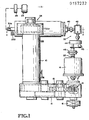
- the overall hoist system is best shown in Fig. 1 and includes a drum 10 driven through a power transmission main drive 12 by a main drive motor 14.
- the motor is provided with a conventional operating brake 16.
- a unique torque limiting device 18 of the type shown in U.S. Patent 4,175,727 is provided in the main drive.
- the details of the torque limiting device are shown in Patent 4,175,727, the disclosure of which is incorporated herein by reference thereto.
- the torque-limiting device includes a set of friction discs which are pre-compressed together to transmit only a limited amount of torque.
- the purpose of the torque-limiting device is to dissipate the high-speed kinetic energy of the upstream or high-speed components of the drive and motor in the event of two-blocking, load-hangup, or other hazard condition.
- the motor shaft 20 of the system shown is the last upstream or high-speed load-carrying component of the winch system. That is, if the motor shaft should break and the motor can no longer support the load, then the load would drop but for the operating brake 16. Sometimes, however, the operating brake 16 is placed upstream of the motor 14 on the motor shaft 20. The brake shaft then becomes the highest upstream load-carrying component of the drive.
- a conventional one-way or sprag clutch 19 allows the motor to power rotation of the main drive in a hoist direction but prevents the motor from powering the main drive in a lowering direction. This feature precludes the motor from inadvertently increasing the load on the worm 30 in an emergency condition.
- down-driving or powered lowering of the main drive is not a requirement or the sizing of the worm is such as to accommodate overloads. In such cases, the sprag 19 is not required.
- the drum is uniquely engaged by a worm gear assembly 24 at all times.
- the drum is attached to a conventional worm wheel 26 having teeth 28.
- a worm 30 having teeth 31 in mesh with the worm wheel teeth is journaled in a housing 32.
- a standard worm brake system illustrating essentially a worm and a worm wheel and the advantages derived therefrom can be found in Patent 3,836,121, the details of which are incorporated herein by reference thereto. As will be explained below, one end of the worm is driven in general synchronism with the worm wheel but at a greater speed either by a separate secondary motor, as in Patent 3,836,121, or by a secondary drive from the main drive motor 14.
- the opposite end of the worm can be splined for axial movement relative to and be driven by a small auxiliary motor and gear reduction unit 34 brought into operation by a normally open clutch 36.
- the unit 34 normally is not connected to the worm, but rather is available as an emergency load lowering or hoisting device in the event a hazard condition has occurred. That is, should the main drive fail, the worm wheel will jam against the worm 30 and stop the drum. The load can then be lowered by coupling the drive unit 34 through the clutch 36 to rotate the worm and thus allow the drum to rotate slowly and lower the load.
- the worm wheel in this instance is the last convenient downstream or last low-speed component of the drive system. If desired, the worm wheel could be placed on a pinion which is in meshing engagement with a bull gear or the like on the drum. The worm wheel would remain the last low-speed, load-carrying component of the system even though coupled to the drum by the pinion.
- the worm preferably has a non-reversing gear ratio; therefore the worm wheel, and thus the drum, cannot rotate at a significantly different rate of speed or in a direction opposite to that in which the worm is being driven.
- the worm is shown as driven by a secondary drive 39, including a shaft 40 which is coupled through a right angle drive 42 to a gear reduction unit 44.
- the gear reduction unit is driven through a conventional electrical or mechanical centrifugal clutch 46.
- An overspeed switch 45 is also coupled to the secondary drive to stop the motor 14 and set the operating brake 16 in an overspeed condition.
- an overspeed switch need not be used as the electrical power controls to that secondary motor, and thus the speed of that secondary motor, will function independently of the main drive motor 14 and will lock up the worm wheel if motor 14 goes overspeed.
- the worm will be driven by the secondary drive in general synchronism both in speed and direction to that of the worm wheel. That is, the drive to both the worm wheel and the worm in the embodiment of Figs. 1 and 2 originates from the motor shaft 20, with the gear reduction units in the main drive and in the gear reduction unit 44 matched to provide general predetermined speed ratios between the two. As will be explained below, the ratios are not exactly the same, since, as a unique part of this invention, the worm will be driven at a velocity greater than that of the worm wheel. The drive to the worm will thus be termed an "accelerating drive.”
- the housing 32 in the embodiment of Fig. 2 is provided with a left-hand clutch face 50 that is coupled to shaft 40 by splines 41.
- a right-hand clutch face 54 is pinned to the left-hand clutch face 50.
- the clutch faces are one form of releasable coupling means.
- the clutch faces are centered for resilient movement left or right by compression springs 52 and 53. The clutch faces then are rotated so as to rotate the worm in the same direction as the worm wheel 26, but at a higher speed.
- Clutch plates 60 and 61 are spragged as at 60a and 61a (lock up in one direction, freely rotate in the other direction) for rotation fixed to the worm in opposite directions. That is, in a hoisting direction, one clutch plate is locked, while the other clutch plate freely rotates on the worm. In the lowering direction, the previously locked clutch plate can fully rotate and the previously freely rotating clutch plate becomes fixed to the worm.
- the sprags are conventional and are provided to prevent the worm from locking up when (1) an operator changes the hoist to move suddenly from lowering to hoisting direction, or vice versa, or (2) a two-blocking occurs.
- High tooth tangential friction may also result when the worm wheel rotates against the stationary worm following reversal of the direction of the drum, for example from hoisting to lowering, since the worm will not be driven until all of the backlash has been taken out of the drive train and the secondary drive 39.
- the worm assembly performs three basic functions: (1) levels out the effects of gear backlash and accumulated slippage in the torque limiter 18; (2) limits the tangential tooth friction between the worm and the worm wheel during normal operations; and (3) drives the worm tooth out of engagement with the worm wheel tooth at a higher torque than the engagement torque between the teeth of the worm wheel and worm.
- the two clutch faces 50 and 54 are operable to drive the worm only in the direction to move a tooth out of engagement with the tooth on the worm wheel and only when such engagement occurs.
- Figs. 5A-5D show the automatic clutch operation which moves the worm tooth away from the worm wheel tooth.
- the tooth 28 on the worm wheel is moving at velocity V 1 and begins to engage tooth 31 on worm 30 until tooth 31 is moving at velocity V 2 equal to V l . This shifts the worm 30 to the right in Fig.
- Fig. 5C shows that once the tooth 31 leaves engagement with the tooth 28, the central clutch plate and right-hand clutch face separate so that the connection between the worm and clutch begins to slip. This results in the worm tooth 31 and worm wheel tooth 28 pushing pressure approximately equaling the slipping drive torque between the clutch plate and clutch face.
- This engagement of the worm wheel and worm teeth is believed to balance the torque transmitted by the slipping clutch plate and clutch face to cause a general synchronism between the worm wheel tooth and worm tooth velocities, although the worm and worm wheel teeth may be intermittently moved into and out of contact during this condition.
- the worm may be immersed in oil to decrease the amount of frictional contact between the worm tooth and the worm wheel.
- Fig. 5D again shown a starting or hoist reversal condition in which the tooth 28 is again pushing worm tooth 31 to axially move the worm as in Fig. 5A.
- Polyurethane bumpers 58 and 59 or other shock absorbers absorb part of the shock loading on the worm when the worm locks the worm wheel in a hazard condition. Most of the system kinetic energy and all of the motor torque will be absorbed by the torque limiter 18 until the motor 14 stops. While the drive to shaft 40, described in the embodiment of Fig. 2, is from a secondary drive 39 from the main drive and motor 14, it should be understood that the drive to shaft 40 can also be a separate secondary drive such as an independent motor of the type shown in Patent 3,836,121.
- Fig. 4 illustrates another embodiment of a worm assembly 24a.
- the worm also has a hex fitting 30a for manually lowering the load, and similarly is axially splined to a normally open clutch 36 and an auxiliary motor and gear reduction 34 for inching the load.
- Still another alternative is to design the worm teeth to allow the worm to be back-driven slightly by the worm wheel for lowering and then place a brake or motor on the worm to provide controlled lowering or raising of the load.
- the worm 30 meshes with a worm wheel 26 in the same manner as in Fig. 2.
- a worm housing 65 rotatably mounts a right clutch face assembly 66 and a left clutch face assembly 68.
- a secondary motor and gear reduction 70 provides the power for rotating the clutch assemblies.
- the motor and gear reduction 70 are sized with an inadequate torque to turn the worm wheel when carrying a load.
- the secondary motor and gear reduction 70 also eliminate the need for separate overspeed devices since the controls to the motor and gear reduction 70 determine the speed thereof independently of the main drive speed.
- the drive could be a secondary drive from the main drive, such as that shown in Fig. 1.
- the clutch assemblies 66 and 68 are rotated but journaled freely on the worm 30. They are rotated at a speed, however, that will move a tooth on the worm 30 at a greater speed than the tooth on the worm wheel 26, as earlier described.
- These clutch assemblies 66 and 68 are known as conical clutches. They are adapted to mate with conical left-hand and right-hand inner clutch plates 72 and 74, respectively.
- the clutch assemblies 66 and 68 and clutch plates 72 and 74 are another form of releasable coupling means.
- inner clutch plates are journaled for free rotation in opposite directions to one another respectively on the worm 30 by sprag or one-way clutches 76 and 78, but are keyed to lock and move with the worm when rotated respectively in the opposite directions.
- a shock-absorbing spring 80 will center the clutch plates and absorb the partial kinetic energy of the system should the worm in an emergency stop be moved either to the right or to the left. For example, if the worm gets pushed to the right, the worm will push inner clutch plate 72 to the right, which will push spring 80 against inner clutch plate 74, and hence against clutch assembly 66, which is fixed against axial movement and the worm will be rotated by clutch assembly 66.
- Fig. 4 illustrates the condition at the time tooth 28 is pushing a tooth 31 on the worm to the left.
- the worm 64 has shifted slightly to the left to engage inner clutch plate 72 with the outer face of clutch assembly 68. This is the same condition as Fig. 5B, in which the tooth 31 will now be advancing away from the tooth 28. As the tooth 31 moves away from tooth 28, the worm 64 will no longer be moved axially by the worm wheel. This will cause clutch plate 72 to slip in assembly 68, and the worm will begin to slow down until an approximate equilibrium is reached between the tooth pushing force and the slipping clutch torque.
- a secondary drive 90 to the worm 30 is driven from the main drive motor 14 (not shown) of the same configuration as in F ig. 1.
- the secondary drive includes the brake 16 attached to the main drive motor shaft 20, the electric normally engaged clutch 46 and may include a mechanical centrifugal normally engaged clutch 47.
- the worm 30 is shown, it being understood that the worm is meshed with a worm wheel, which again is connected to the drum 10, as shown in Figs. 1 and 2.
- the torque is varied dependent upon the axial position of the worm and the relative directions of the worm and worm wheel.
- the worm is driven through a differential mechanism 92 and a clutching mechanism 94.
- the secondary drive from the motor 14 via clutch 47 drives an input gear 96 which meshes with a side input gear 97.
- the side input gear is journaled on a differential shaft 98 and fixed to a first bevel gear 100 that is also journaled on shaft 98.
- First bevel gear 100 meshes with a central second bevel gear 102 that is rotatably journaled on a differential carrier 104 that is pinned to shaft 98.
- a gear 106 meshes with gear 102 and is rotatably mounted on shaft 98.
- Gear 106 is fixed to a side output gear 108.
- the side output gear 108 is rotatably mounted on shaft 98 and meshes with an output gear 109 that is keyed to a shaft 105 that is splined to a shaft 107.
- Shaft 107 is splined in the worm 30.
- the worm 30 is mounted for limited axial movement, and centered in brackets 113 by positioning springs 118 (Fig. 6).
- the worm 30 is mounted for rotation in the brackets 113, which are fixed to a slide 114.
- the slide 114 can reciprocate in a track 115 of a frame 116.
- Heavy shock-absorbing springs 110 and 112 center the slide in the frame. Shock-absorbing springs 110 and 112 provide partial shock absorption of the lower speed components of the main drive train and drum in an emergency stop situation.
- a switch actuator ring 120 moves with axial movement of the worm 30.
- This actuator ring engages a switch actuator roller 122 biased by a spring 122a, the roller positions a switch operator arm 124.
- the switch 125 has a pivotal post 125a fixed to arm 124. The post is fixed to a cam operator 125b that rocks a cam follower switch bar 125c. When cam operator 125b is close to its center between "1" and "r,” one set of switch contacts will be closed and the other opened.
- This switch contact change represents the condition when the worm tooth has been moved away at a high torque from a worm wheel tooth, but prior to the worm tooth engaging a next forward worm wheel tooth.
- the total axial excursion of the worm is represented by distance "a" (Fig.
- the worm is at the end of an axial excursion when running in one normal direction because the differential worm drive runs at a faster velocity than the tangential speed of the wheel.
- the worm Upon a reversal, the worm is moved in the opposite direction at a higher torque until the ring 120 and thus the operator 125b reach a position between "r" and "1". At this location, the torque is decreased until the worm is again pushing slightly against the worm wheel tooth at the full excursion of the distance "a.”
- respective conventional brakes 128 and 130 are energized or de-energized to increase the torque available out of the planetary to gear 109.
- the torque created by the brakes 128 and 130 is greater than the torque created on gear 109 by a drag 150 described later.
- the increased torque is necessary to overcome the frictional engagement of the worm wheel tooth against the worm tooth following a hoist reversal.
- the gear on the opposite brake shaft will be locked to its brake shaft through its one way sprague, but since that brake is not set on that shaft, the entire brake shaft can rotate.
- the choice of which brake 128 or 130 is energized (set) and which is de-energized (not set) is determined from the switch 125 and is dependent upon the position of switch arm 124 and thus operator 125b, which monitors the axial position of the worm 30.
- the brake 128 will be set and the other brake 130 will be de-energized to allow the transfer gear to rotate and accelerate the worm at a speed greater than the speed of the worm wheel and in the same direction as the worm wheel.
- Differential shaft 98 is held with a slight drag by a friction device 150 of a conventional type. Therefore, the resistance of 150 imposes a constant predetermined limited torque on gear 108 through the differential assembly. With this motion, the worm is advanced toward the next forward tooth of the worm wheel at a limited torque, but at a speed slightly greater than the worm wheel speed. This will cause the worm tooth to engage the next forward worm wheel tooth with a slight drag resulting from the drag 150.
- the three functions carried out by this system are: first, to accommodate accumulated slip in the torque-limiting device 18 where there is such a device in the system; second, to provide sufficient torque for the worm tooth to move away from the tooth it was contacting when the operator reverses the hoist; and finally, to provide the intelligence through the switch 125 to tell when the worm has begun to move away from the worm wheel tooth it has been pushing against. That is, the worm is always allowed to catch up in this embodiment to the worm wheel tooth which is ahead of it in its direction of movement; but during a reversal, it must get out of the way and requires more torque to do this.
- Fig. 7 shows still another embodiment in which the slide 114 can be used to actuate a switch and set a brake band 200 on the drum or can act through a bell crank 210 or other suitable mechanism to provide the motive power to set the brake 200.
- Suitable brake setting arrangements are shown in earlier identified applications Serial Nos. 475,684 and 317,054, the details of which are incorporated herein by reference thereto.
- the slide will be moved axially by the worm 30 to compress springs 110 or 112 in a hazard condition. Rather than the worm then acting to stop the worm wheel and thus the drum, the brake on the drum which is set by movement of the worm stops the drum.
- the worm may be sized much smaller than would be necessary if the worm had to absorb the kinetic energy of the drum, load and drive train as in the embodiments shown in Figs. 1-6. In this embodiment the energy is absorbed by the brake 200.
Landscapes
- Engineering & Computer Science (AREA)
- Mechanical Engineering (AREA)
- Gear Transmission (AREA)
- Jib Cranes (AREA)
- Transmission Devices (AREA)
Applications Claiming Priority (2)
| Application Number | Priority Date | Filing Date | Title |
|---|---|---|---|
| US06/590,630 US4625946A (en) | 1984-03-19 | 1984-03-19 | Hoist having worm safety device |
| US590630 | 1990-09-28 |
Publications (1)
| Publication Number | Publication Date |
|---|---|
| EP0157232A1 true EP0157232A1 (fr) | 1985-10-09 |
Family
ID=24363003
Family Applications (1)
| Application Number | Title | Priority Date | Filing Date |
|---|---|---|---|
| EP85102749A Ceased EP0157232A1 (fr) | 1984-03-19 | 1985-03-11 | Treuil pourvu d'un dispositif de sécurité à vis sans fin |
Country Status (3)
| Country | Link |
|---|---|
| US (1) | US4625946A (fr) |
| EP (1) | EP0157232A1 (fr) |
| JP (1) | JPS60209498A (fr) |
Cited By (4)
| Publication number | Priority date | Publication date | Assignee | Title |
|---|---|---|---|---|
| FR2914263A1 (fr) * | 2007-04-02 | 2008-10-03 | Sita | Treuil pour wagon porte-vehicules et wagon le comportant |
| EP2253578A1 (fr) * | 2009-05-20 | 2010-11-24 | Gebr. Wittler GmbH & Co. KG | Treuil de charge à entraînement électrique |
| CN104245560A (zh) * | 2011-04-01 | 2014-12-24 | 西格恩工程简易股份有限公司 | 一种包含配备在升降设备,特别是绞车上的安全装置及执行所述安全装置的操作系统的设备 |
| CN105377741A (zh) * | 2013-03-20 | 2016-03-02 | 阿克森Ep股份有限公司 | 绞车系统 |
Families Citing this family (20)
| Publication number | Priority date | Publication date | Assignee | Title |
|---|---|---|---|---|
| US5163570A (en) * | 1991-05-28 | 1992-11-17 | Paccar Inc. | Load sensing device for a boom mounted on a vehicle |
| DE19951221A1 (de) * | 1999-04-01 | 2000-10-05 | Mannesmann Ag | Windwerk, insbesondere Hebezeug, mit einem Gehäuse |
| FR2824058B3 (fr) * | 2001-04-25 | 2003-06-27 | Yavor Pachov | Dispositif de freinage de securite d'un organe rotatif |
| FR2824057A1 (fr) * | 2001-04-25 | 2002-10-31 | Yavor Pachov | Suiveur d'entrainement de securite irreversible |
| US20080156132A1 (en) * | 2003-10-29 | 2008-07-03 | Yavor Pachov | Safety system |
| US7331252B2 (en) * | 2003-10-29 | 2008-02-19 | Yavor Pachov | Braking system |
| US8925412B2 (en) | 2003-10-29 | 2015-01-06 | Yavor Pachov | Safety system |
| CN100515914C (zh) * | 2006-08-17 | 2009-07-22 | 谢玉枝 | 电动绞车锥面刹车装置 |
| NL2000443C2 (nl) * | 2007-01-18 | 2008-07-22 | Imc Corporate Licensing B V | Lier. |
| US8924892B2 (en) | 2008-08-22 | 2014-12-30 | Fuji Xerox Co., Ltd. | Multiple selection on devices with many gestures |
| US7850147B1 (en) | 2008-08-23 | 2010-12-14 | Superior Gearbox Company | Boat lifting apparatus |
| DE102010026968B4 (de) * | 2010-07-13 | 2014-02-13 | Liebherr-Components Biberach Gmbh | Winde sowie Baumaschine oder Hebegerät |
| KR101231862B1 (ko) * | 2010-10-26 | 2013-02-08 | 한국수력원자력 주식회사 | 천장이동장치용 z축 이중화 동력전달장치 |
| RU2598113C2 (ru) * | 2012-03-28 | 2016-09-20 | Сигурен Инджениерие | Блок безопасности подъёмника |
| DE102015009057A1 (de) * | 2015-07-07 | 2017-01-12 | Esw Gmbh | Seilwinde, Verfahren zum Steuern eines Betriebes einer Seilwinde und Verfahren zum Betreiben einer Seilwinde |
| DE102017100581A1 (de) * | 2017-01-13 | 2018-07-19 | Andreas Heiko Gruner | Spannvorrichtung zum Spannen einer Schraubenfeder |
| DE202017105348U1 (de) * | 2017-09-05 | 2018-12-07 | Liebherr-Components Biberach Gmbh | Freifallwinde |
| CN109665418A (zh) * | 2017-10-17 | 2019-04-23 | 陕西小溪机电科技有限公司 | 一种电梯曳引机构 |
| CN110520347B (zh) * | 2018-03-08 | 2021-12-14 | 卡沃汽车工业及贸易股份公司 | 具有轮胎自下降机构和锁的备胎绞盘 |
| FR3107937B1 (fr) * | 2020-03-03 | 2022-06-17 | Cie Engrenages Et Reducteurs Messian Durand | Dispositif d’entraînement et tiltrotateur correspondant |
Citations (7)
| Publication number | Priority date | Publication date | Assignee | Title |
|---|---|---|---|---|
| FR595874A (fr) * | 1924-06-28 | 1925-10-10 | Atlas Werke Ag | Treuil électrique pour ancre ou cabestan à accouplement de sûreté |
| US3102434A (en) * | 1959-10-16 | 1963-09-03 | Murphy Diesel Company | Automatic control of output reversal in slippable drives for transmitting torque |
| FR2189302A1 (fr) * | 1972-06-23 | 1974-01-25 | Transfer Systems | |
| GB2015461A (en) * | 1978-03-06 | 1979-09-12 | Ederer Inc | Hoist safety device |
| US4177973A (en) * | 1978-03-06 | 1979-12-11 | Ederer Incorporated | Cable drum safety brake |
| GB2031363A (en) * | 1978-10-17 | 1980-04-23 | Northern Eng Ind | Crane Safety System |
| WO1982001700A1 (fr) * | 1980-11-07 | 1982-05-27 | Inc Ederer | Mecanisme de securite pour tambours de levage |
Family Cites Families (16)
| Publication number | Priority date | Publication date | Assignee | Title |
|---|---|---|---|---|
| US647239A (en) * | 1898-07-27 | 1900-04-10 | Sprague Electric Co | Elevator. |
| US898782A (en) * | 1908-01-28 | 1908-09-15 | Gustav Rasmus | Electric hoist. |
| US1490671A (en) * | 1923-03-17 | 1924-04-15 | Alonzo B See | Elevator |
| US1768420A (en) * | 1923-03-17 | 1930-06-24 | Gen Electric | Apparatus for towing, mooring, and the like |
| US1885458A (en) * | 1930-03-15 | 1932-11-01 | Joseph Maniscalco | Speed control for elevators |
| AT140640B (de) * | 1932-05-12 | 1935-02-11 | Haniel & Lueg Gmbh | Bohrdruckregelung für Tiefbohranlagen. |
| US2300343A (en) * | 1941-01-24 | 1942-10-27 | Murray G Clay | Hoisting mechanism |
| DE895514C (de) * | 1942-01-14 | 1953-11-02 | Atlas Werke Ag | Zugeinrichtung, insbesondere Schleppwinde fuer Schiffe |
| US2652230A (en) * | 1949-02-16 | 1953-09-15 | Lake Shore Engineering Company | Winch |
| US2903901A (en) * | 1957-02-25 | 1959-09-15 | Us Rubber Co | Transmission |
| US2884800A (en) * | 1957-05-01 | 1959-05-05 | Duff Norton Co | Worm drive mechanism |
| US3063708A (en) * | 1958-05-09 | 1962-11-13 | Honsberg Geb | Electro-mechanical clamping drive with electric control |
| GB950003A (en) * | 1961-08-14 | 1964-02-19 | Scott L & Electromotors Ltd | Improvements in or relating to winches, capstans and the like |
| FR1520606A (fr) * | 1967-02-20 | 1968-04-12 | Potain & Cie Ets F | Perfectionnements aux treuils pour la commande d'appareils de levage du genre des grues, ponts roulants au analogues |
| US3572482A (en) * | 1969-01-03 | 1971-03-30 | Us Army | Automatic clutch and brake for hoists |
| US3541888A (en) * | 1969-04-14 | 1970-11-24 | Warn Belleview Inc | Mechanical power transmitting mechanism |
-
1984
- 1984-03-19 US US06/590,630 patent/US4625946A/en not_active Expired - Fee Related
-
1985
- 1985-03-11 EP EP85102749A patent/EP0157232A1/fr not_active Ceased
- 1985-03-19 JP JP60055617A patent/JPS60209498A/ja active Pending
Patent Citations (7)
| Publication number | Priority date | Publication date | Assignee | Title |
|---|---|---|---|---|
| FR595874A (fr) * | 1924-06-28 | 1925-10-10 | Atlas Werke Ag | Treuil électrique pour ancre ou cabestan à accouplement de sûreté |
| US3102434A (en) * | 1959-10-16 | 1963-09-03 | Murphy Diesel Company | Automatic control of output reversal in slippable drives for transmitting torque |
| FR2189302A1 (fr) * | 1972-06-23 | 1974-01-25 | Transfer Systems | |
| GB2015461A (en) * | 1978-03-06 | 1979-09-12 | Ederer Inc | Hoist safety device |
| US4177973A (en) * | 1978-03-06 | 1979-12-11 | Ederer Incorporated | Cable drum safety brake |
| GB2031363A (en) * | 1978-10-17 | 1980-04-23 | Northern Eng Ind | Crane Safety System |
| WO1982001700A1 (fr) * | 1980-11-07 | 1982-05-27 | Inc Ederer | Mecanisme de securite pour tambours de levage |
Cited By (5)
| Publication number | Priority date | Publication date | Assignee | Title |
|---|---|---|---|---|
| FR2914263A1 (fr) * | 2007-04-02 | 2008-10-03 | Sita | Treuil pour wagon porte-vehicules et wagon le comportant |
| EP2253578A1 (fr) * | 2009-05-20 | 2010-11-24 | Gebr. Wittler GmbH & Co. KG | Treuil de charge à entraînement électrique |
| CN104245560A (zh) * | 2011-04-01 | 2014-12-24 | 西格恩工程简易股份有限公司 | 一种包含配备在升降设备,特别是绞车上的安全装置及执行所述安全装置的操作系统的设备 |
| CN104245560B (zh) * | 2011-04-01 | 2016-11-16 | 西格恩工程简易股份有限公司 | 一种包含配备在升降设备,特别是绞车上的安全装置及执行所述安全装置的操作系统的设备 |
| CN105377741A (zh) * | 2013-03-20 | 2016-03-02 | 阿克森Ep股份有限公司 | 绞车系统 |
Also Published As
| Publication number | Publication date |
|---|---|
| US4625946A (en) | 1986-12-02 |
| JPS60209498A (ja) | 1985-10-22 |
Similar Documents
| Publication | Publication Date | Title |
|---|---|---|
| US4625946A (en) | Hoist having worm safety device | |
| US4493479A (en) | Hoist drive safety system | |
| US4103872A (en) | Overload protection apparatus for hoisting machine | |
| EP3242850B1 (fr) | Arrangement de système de mécanismes de levage et procédé pour faire fonctionner l'arrangement de système | |
| CA2049194A1 (fr) | Frein de treuil en charge | |
| EP0046752B1 (fr) | Entrainement a engrenage a freinage rapide-lent | |
| US4508318A (en) | Electric hoist | |
| US4653653A (en) | Hoisting systems | |
| JPH0633155B2 (ja) | レバー式捲上機 | |
| KR102199659B1 (ko) | 전자브레이크가 없는 무대장치용 리프트 구동장치 | |
| US4986400A (en) | Bi-directional spring clutch for reducing worm gear drive | |
| US4370896A (en) | Reversing device for a gear transmission | |
| US3539041A (en) | One way brake deactivated by drive and one way clutch | |
| UA53673C2 (uk) | Лебідка з приводом від роздавальної коробки транспортного засобу | |
| EP0064080B1 (fr) | Mecanisme de securite pour tambours de levage | |
| US3602345A (en) | Jaw clutch | |
| JP2015514048A (ja) | 昇降機構、特にウィンチを備えた安全装置、及び当該装置を作動するシステムを備えるアセンブリ | |
| EP0243431B1 (fr) | Dispositif d'embrayage et procede de commande du mouvement de l'arbre d'un appareil de hissage | |
| JPH0617829Y2 (ja) | ウインチ装置 | |
| JPH05238680A (ja) | 電動巻上装置 | |
| EP0331362B1 (fr) | Dispositif d'engagement retardé d'une transmission | |
| US3180467A (en) | Safety device for air clutch | |
| JPH0716697Y2 (ja) | 建設現場におけるエレベーターの落下防止装置 | |
| KR102145940B1 (ko) | 전기 기계식 조타 장치 | |
| SU1258809A1 (ru) | Ручна лебедка |
Legal Events
| Date | Code | Title | Description |
|---|---|---|---|
| PUAI | Public reference made under article 153(3) epc to a published international application that has entered the european phase |
Free format text: ORIGINAL CODE: 0009012 |
|
| AK | Designated contracting states |
Designated state(s): AT BE CH DE FR GB IT LI LU NL SE |
|
| 17P | Request for examination filed |
Effective date: 19860307 |
|
| 17Q | First examination report despatched |
Effective date: 19861016 |
|
| STAA | Information on the status of an ep patent application or granted ep patent |
Free format text: STATUS: THE APPLICATION HAS BEEN REFUSED |
|
| 18R | Application refused |
Effective date: 19880410 |
|
| RIN1 | Information on inventor provided before grant (corrected) |
Inventor name: CLARK, CHARLES WILLIAM, JR. Inventor name: WEST, HAROLD HENRY |