EP0157470A2 - Magnetfeldsensor - Google Patents
Magnetfeldsensor Download PDFInfo
- Publication number
- EP0157470A2 EP0157470A2 EP85300418A EP85300418A EP0157470A2 EP 0157470 A2 EP0157470 A2 EP 0157470A2 EP 85300418 A EP85300418 A EP 85300418A EP 85300418 A EP85300418 A EP 85300418A EP 0157470 A2 EP0157470 A2 EP 0157470A2
- Authority
- EP
- European Patent Office
- Prior art keywords
- flux concentrator
- hall element
- hall
- sensor
- magnetic field
- Prior art date
- Legal status (The legal status is an assumption and is not a legal conclusion. Google has not performed a legal analysis and makes no representation as to the accuracy of the status listed.)
- Ceased
Links
- 230000005291 magnetic effect Effects 0.000 title claims abstract description 42
- 230000004907 flux Effects 0.000 claims abstract description 50
- 230000005355 Hall effect Effects 0.000 claims abstract description 34
- 230000005284 excitation Effects 0.000 claims abstract description 13
- 239000005300 metallic glass Substances 0.000 claims description 8
- 238000000034 method Methods 0.000 claims description 7
- 229910001218 Gallium arsenide Inorganic materials 0.000 claims description 4
- 230000035699 permeability Effects 0.000 claims description 4
- 238000001228 spectrum Methods 0.000 claims description 4
- 238000004804 winding Methods 0.000 description 13
- 239000011162 core material Substances 0.000 description 10
- 238000001514 detection method Methods 0.000 description 6
- 239000000919 ceramic Substances 0.000 description 4
- 230000035945 sensitivity Effects 0.000 description 4
- 239000000758 substrate Substances 0.000 description 4
- 230000005294 ferromagnetic effect Effects 0.000 description 2
- 239000000463 material Substances 0.000 description 2
- 239000004065 semiconductor Substances 0.000 description 2
- 230000001419 dependent effect Effects 0.000 description 1
- 230000000694 effects Effects 0.000 description 1
- 230000007774 longterm Effects 0.000 description 1
- 239000000696 magnetic material Substances 0.000 description 1
- 230000010363 phase shift Effects 0.000 description 1
- 238000011896 sensitive detection Methods 0.000 description 1
Images


Classifications
-
- G—PHYSICS
- G01—MEASURING; TESTING
- G01R—MEASURING ELECTRIC VARIABLES; MEASURING MAGNETIC VARIABLES
- G01R33/00—Arrangements or instruments for measuring magnetic variables
- G01R33/02—Measuring direction or magnitude of magnetic fields or magnetic flux
- G01R33/06—Measuring direction or magnitude of magnetic fields or magnetic flux using galvano-magnetic devices
- G01R33/07—Hall effect devices
-
- G—PHYSICS
- G01—MEASURING; TESTING
- G01R—MEASURING ELECTRIC VARIABLES; MEASURING MAGNETIC VARIABLES
- G01R33/00—Arrangements or instruments for measuring magnetic variables
- G01R33/02—Measuring direction or magnitude of magnetic fields or magnetic flux
- G01R33/04—Measuring direction or magnitude of magnetic fields or magnetic flux using the flux-gate principle
-
- H—ELECTRICITY
- H10—SEMICONDUCTOR DEVICES; ELECTRIC SOLID-STATE DEVICES NOT OTHERWISE PROVIDED FOR
- H10N—ELECTRIC SOLID-STATE DEVICES NOT OTHERWISE PROVIDED FOR
- H10N52/00—Hall-effect devices
- H10N52/80—Constructional details
Definitions
- This invention relates to magentic field sensors.
- a magnetic field sensor comprising a Hall effect device with a Hall element (13) and flux concentrator means (11,12) associated with the Hall element; means (14,15,16) for generating a varying magnetic field in the flux concentrator means (11,12) such as to drive said flux concentrator means alternately into and out of magnetic saturation, and means (19) for detecting a second harmonic term in the output voltage of the Hall element (13) when a Hall current is applied to the Hall element and in the presence of a d.c. magnetic field, the amplitude of said second harmonic term providing a measure of the d.c. magnetic field.
- a method of sensing a magnetic field including the steps of generating a varying magnetic field in flux concentrator means (11,12) of a Hall effect device including a Hall element (13), said flux concentrator means being associated with said Hall element, such as to drive said flux concentrator means alternately into and out of magentic saturation, applying a Hall current to said Hall element and applying the output voltage of the Hall element to means (19) for detecting a second harmonic term therein, which second harmonic term is generated by a d.c. magnetic field to be sensed when the Hall effect device is disposed therein.
- the amplitude of the primary winding exciting current is adjusted in order to drive the core 1 into saturation.
- Graphs of the magnetic field intensity (H) in the core, which is proportional to the primary winding exciting current, and the flux density (B) in the core versus time are shown in Figs. 2a and 2b, respectively (solid lines). These graphs assume a triangular waveform from the signal generator 4 and that the B-H curve for the core material is linear up to saturation and then becomes flat (Fig. 2c).
- the voltage output from the secondary winding 3 is proportional to dB/dt and hence is a rectangular wave as shown in Fig. 2d. If the B versus time waveform (Fig. 2b) is symmetric then the positive and negative pulses of the secondary winding voltage are equal in 0 amplitude and 180 out of phase. Analysis of this waveform has shown that the second harmonic component 'is zero. If this conventional fluxgate magnetometer is placed in a d.c. magnetic field which is directed along the core 1, as indicated by the arrows in Fig. 1, then an offset is produced in the H versus time and B versus time graphs, as indicated by the dashed lines in Figs. 2a and 2b.
- the secondary winding output voltage may be bandpass filtered as at 6 (Fig. 1) in order to remove signal components other than the second harmonic component, which is amplified as at 7 and then detected by a phase sensitive detector 8.
- the polarity of the output as indicated on meter 9 is determined by the direction of the d.c. magnetic field.
- a frequency doubler 10 serves to provide a reference for detector 8.
- Hall effect device which, as is well known, comprises a platelike body of a semiconductor material through which a transverse magnetic field may be applied.
- the effect of the magnetic field is to deflect an electric current flowing across the body between a pair of current electrodes, this deflection of the current introducing a potential difference (Hall voltage) between a pair of sensor or Hall electrodes disposed one each side of a line joining the two current electrodes.
- Hall effect devices may have the ability to sense weak magnetic fields (10-100 gamma and below), it has previously been proposed to.provide the devices with flux concentrators as, for example, disclosed in our Application No. 8111812 (Serial No. 2081973)(G.D. Pitt et al 32-7-5X) or our Application No. 8318267 (Serial No.
- the latter specification describes the use of a thin ribbon of a magnetic material of high permeability, for example the metallic glass ribbon sold under the trade name "Vitrovac 6025", for the flux concentrators.
- the plate-like body of semiconductor material may, for example, comprise GaAs. Hall effect devices with metallic glass flux concentrators have sensitivities over two orders of magnitude higher than the conventional Hall effect sensors. However, the offset voltage at zero field and the noise drift levels limit their usefulness.
- Hall effect devices with metallic glass flux concentrators may be employed in such a way as to reduce the minimum detectable magnetic field in a sensor device which works on a similar principle to the conventional fluxgate magnetometer and which we have thus designated as a Hall effect fluxgate magnetometer (Hall.fluxgate, for short).
- a GaAs Hall effect sensor effectively replaces the secondary detector winding of a conventional fluxgate magnetometer and the metallic glass flux concentrator means replace the ferromagnetic core.
- Fig. 3 shows, schematically, an embodiment of a Hall effect fluxgate magnetometer with a flat configuration of flux concentrators, for the detection of linear magnetic fields
- Fig. 4 shows, schematically, a closed loop configuration of a flux concentrator for the detection of circular magnetic fields, such as produced by a d.c. current i passing down a wire extending through the loop.
- the magnetometer shown in Fig. 3 comprises a ceramic substrate 10, a first or lower thin-ribbon-form metallic glass flux concentrator 11 with a tapered end portion, a second or upper thin-ribbon-form metallic glass flux concentrator 12 with a tapered end portion and a GaAs Hall effect chip 13 disposed between the tapered end portions of the concentrators 11 and 12, which concentrators 11 and 12 together compr.ise the above referred to flux concentrator means.
- the flux concentrators may be bonded to the ceramic substrate with their tapered end portions overlapping and the chip 13'- disposed therebetween.
- the chip 13 may be bonded to one or both of the flux concentrators but is not electrically connected thereto.
- An excitation coil 14 is shown wound around the flux concentrator 12, alternatively the central area of the Hall effect sensor that is the ceramic substrate and the members bonded thereto may be disposed within a coil with the flux concentrators 11 and 12 extending axially from opposite sides thereof.
- ⁇ An a.c. excitation current is supplied to the coil 14 from a signal generator 15, a digital multimeter (DMM) unit 16 being incorporated in order to measure the excitation current.
- the Hall effect chip 13 has four electrodes which may be coupled by interconnection wires (not shown) to conductive tracks (not shown) on the ceramic substrate to which external connections can be made to a power supply for the Hall chip and means for detecting the Hall output voltage.
- a d.c. power supply is indicated at 17, an ammeter 18 being incorporated in the supply circuit to indicate the Hall current supplied.
- the Hall output voltage is indicated as applied to a unit 19 for detection purposes.
- the unit 19 may be a spectrum analyser.
- the flux concentrator may comprise a lock-in amplifier with a reference signal derived from the signal generator 15 and coupled thereto over line 19a, the reference signal being at the same frequency as the excitation current.
- the flux concentrator/Hall chip arrangement of Fig. 3 may be replaced directly by the closed loop single flux concentrator of Fig. 4. Identical reference numerals being used for identical parts. In this case the flux concentrator is a single element 11 1 .
- the amplitude of .the a.c. excitation current is chosen to be sufficient to drive the flux concentrators into magnetic saturation.
- the output from the Hall effect chip With no d.c. magnetic field applied the output from the Hall effect chip, when the Hall circuit is applied thereto, will contain only odd harmonics.
- the output from the Hall effect device is proportional to B rather than dB/dt, so that the Hall voltage signal produced has a waveform of the Fig. 2b type rather than the Fig. 2d type. This waveform is symmetric, in the absence of a d.c. magnetic field, and the resultant second harmonic component is thus zero.
- the advantage of the Hall effect fluxgate magnetometer over a conventional Hall effect sensor include (a) a nearly zero offset voltage compared to several millivolts of the conventional sensor, (b) a lower noise signal than the conventional sensor, which noise signal limits the minimum detectable field, and (c) a lower long term drift.
- the offset voltage for the Hall effect fluxgate magnetometer is defined as the second harmonic voltage with zero applied d.c. magnetic field.
- the lower offset voltage eliminates the need-for offset voltage compensation circuits.
- the low noise level associated with the second harmonic detection method is due to the fact that noise from the offset voltage is greatly reduced.
- the d.c. signal of the conventional sensor is subject to a large amount of noise generated by fluctuations in the offset voltage.
- the above advantages provide extended operating range and accuracy in comparison with conventional Hall effect sensors.
- The.Hall effect fluxgate magnetometers so far produced have a noise level which is approximately ten times lower than that of the conventional Hall effect (d.c. signal) sensors, however their sensitivity is also lower by a factor of approximately two and a half. Consequently the minimum field detectable by the Hall fluxgate is reduced by a factor of four in comparison with the conventional d.c. Hall sensor.
- the Hall effect fluxgate has a lower sensitivity than a conventional fluxgate but has the advantages of being lighter,'more compact and requiring only a single coil winding.
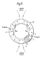
- the Hall effect fluxgate magnetometer with a flux concentrator in the closed loop configuration will respond to linear d.c. magnetic fields as well as circular fields, its response to linear fields being in a similar manner to the conventional ring core magnetic fluxgate (W.A. Geyger, Nonlinear-magnetic control devices. McGraw-Hill, 1964, p331). If there is a component of the linear field in the plane of the loop of the flux concentrator 20, as shown in Fig. 5, then the Hall effect fluxgate detects the field with a sensitivity depending on the position of the Hall chip relative to the direction of the field. In the conventional ring core magnetic fluxgate there are two parts to the detecting winding, which parts are arranged so that the fundamental of the d.c.
Landscapes
- Physics & Mathematics (AREA)
- Condensed Matter Physics & Semiconductors (AREA)
- General Physics & Mathematics (AREA)
- Measuring Magnetic Variables (AREA)
- Magnetic Resonance Imaging Apparatus (AREA)
- Magnetic Treatment Devices (AREA)
Applications Claiming Priority (2)
| Application Number | Priority Date | Filing Date | Title |
|---|---|---|---|
| GB8404967 | 1984-02-25 | ||
| GB08404967A GB2154744B (en) | 1984-02-25 | 1984-02-25 | Magnetic field sensor |
Publications (2)
| Publication Number | Publication Date |
|---|---|
| EP0157470A2 true EP0157470A2 (de) | 1985-10-09 |
| EP0157470A3 EP0157470A3 (de) | 1985-11-27 |
Family
ID=10557179
Family Applications (1)
| Application Number | Title | Priority Date | Filing Date |
|---|---|---|---|
| EP85300418A Ceased EP0157470A3 (de) | 1984-02-25 | 1985-01-23 | Magnetfeldsensor |
Country Status (6)
| Country | Link |
|---|---|
| US (1) | US4692703A (de) |
| EP (1) | EP0157470A3 (de) |
| JP (1) | JPS60194379A (de) |
| AU (1) | AU3849085A (de) |
| GB (1) | GB2154744B (de) |
| NO (1) | NO850682L (de) |
Cited By (4)
| Publication number | Priority date | Publication date | Assignee | Title |
|---|---|---|---|---|
| EP0359922A1 (de) * | 1988-09-13 | 1990-03-28 | Landis & Gyr Betriebs AG | Vorrichtung zur Messung eines magnetischen Feldes |
| FR2700616A1 (fr) * | 1993-01-19 | 1994-07-22 | Thomson Brandt Armements | Détecteur mobile de proximité d'objets ferromagnétiques et mine équipée. |
| WO1995030906A1 (en) * | 1994-05-05 | 1995-11-16 | Denis Frank Spicer | Magnetic field cancelling system |
| WO2007096318A1 (de) * | 2006-02-20 | 2007-08-30 | Siemens Aktiengesellschaft | Sensoreinrichtung zur erfassung einer magnetfeldgrösse |
Families Citing this family (27)
| Publication number | Priority date | Publication date | Assignee | Title |
|---|---|---|---|---|
| US4765345A (en) * | 1987-02-18 | 1988-08-23 | Myo-Tronics Research, Inc. | Magnetic sensor for jaw tracking device |
| WO1988008139A1 (en) * | 1987-04-14 | 1988-10-20 | The Secretary Of State For Defence In Her Britanni | A roll-independent magnetometer system |
| GB8724087D0 (en) * | 1987-10-14 | 1987-11-18 | Westinghouse Brake & Signal | Testing circuit arrangement |
| US4916821A (en) * | 1988-03-04 | 1990-04-17 | Potter Bronson R | Electronic compass and other magnetic devices |
| US5041780A (en) * | 1988-09-13 | 1991-08-20 | California Institute Of Technology | Integrable current sensors |
| US5477675A (en) * | 1989-02-17 | 1995-12-26 | Nartron Corporation | Fluid power assist method and apparatus |
| WO1991011681A1 (en) * | 1990-01-31 | 1991-08-08 | Potter Bronson M | Electronic compass and other magnetic devices |
| DE69306914T2 (de) * | 1992-10-29 | 1997-05-07 | Rolls-Royce And Associates Ltd., Derby, Derbyshire | Verbesserung in Weggebern |
| US5483161A (en) * | 1992-12-11 | 1996-01-09 | The United States Of America As Represented By The Secretary Of Commerce | Faraday effect continuous circuit flux concentrating magnetic field sensor |
| US5973501A (en) * | 1993-10-18 | 1999-10-26 | Metropolitan Industries, Inc. | Current and voltage probe for measuring harmonic distortion |
| US5506505A (en) * | 1994-05-09 | 1996-04-09 | Tdw Delaware, Inc. | Apparatus for remotely indicating pipeline pig including a sensor housing having surface engaging orthogonally disposed paramagnetic materials a solid state sensor and a flag |
| EP0772046B1 (de) * | 1995-10-30 | 2002-04-17 | Sentron Ag | Magnetfeldsensor und Strom- oder Energiesensor |
| GB2315870B (en) * | 1996-08-02 | 2001-01-31 | Ultra Electronics Ltd | Magnetometer |
| JPH11265649A (ja) * | 1998-03-18 | 1999-09-28 | Mitsubishi Electric Corp | 電流検出器及び電流検出器を備えた電力開閉器 |
| US6670809B1 (en) * | 2000-08-18 | 2003-12-30 | The United States Of America As Represented By The Secretary Of The Army | Magnetic sensor with modulating flux concentrator having minimized air resistance for 1/f noise reduction |
| US6501268B1 (en) * | 2000-08-18 | 2002-12-31 | The United States Of America As Represented By The Secretary Of The Army | Magnetic sensor with modulating flux concentrator for 1/f noise reduction |
| EP1260825A1 (de) | 2001-05-25 | 2002-11-27 | Sentron Ag | Magnetfeldsensor |
| WO2004013645A1 (de) | 2002-08-01 | 2004-02-12 | Sentron Ag | Magnetfeldsensor und verfahren zum betrieb des magnetfeldsensors |
| FR2852398B1 (fr) * | 2003-03-13 | 2005-07-22 | Systeme de mesure d'un champ magnetique basse frequence et systeme de modukation d'un champ magnetique mis en oeuvre dans le systeme de mesure | |
| US8358134B1 (en) | 2008-10-24 | 2013-01-22 | Pure Technologies Ltd. | Marker for pipeline apparatus and method |
| US7859256B1 (en) | 2008-11-12 | 2010-12-28 | Electromechanical Technologies, Inc. | Defect discriminator for in-line inspection tool |
| DE102011011247B4 (de) * | 2011-02-15 | 2015-12-31 | Fraunhofer-Gesellschaft zur Förderung der angewandten Forschung e.V. | Sensoranordnung und Verfahren zur Messung von Magnetfeldern |
| JP6476851B2 (ja) * | 2014-12-26 | 2019-03-06 | 富士電機機器制御株式会社 | 電流検知装置 |
| JP6604730B2 (ja) * | 2015-03-17 | 2019-11-13 | エイブリック株式会社 | 半導体装置 |
| KR101868267B1 (ko) | 2017-01-26 | 2018-06-15 | 고려대학교 산학협력단 | 고조파 홀 전압 분석 방법 |
| US20220155352A1 (en) * | 2019-03-18 | 2022-05-19 | Dima Cheskis | Low current hall effect sensor |
| CN115453431B (zh) * | 2022-09-20 | 2025-01-24 | 中国科学院空天信息创新研究院 | 一种基于声波激励磁电天线的复合型三轴霍尔传感器 |
Family Cites Families (12)
| Publication number | Priority date | Publication date | Assignee | Title |
|---|---|---|---|---|
| GB1103536A (de) * | 1900-01-01 | |||
| DE1106410B (de) * | 1956-09-28 | 1961-05-10 | Siemens Ag | Elektrisches Messgeraet fuer insbesondere schwache magnetische Felder |
| GB868765A (en) * | 1957-07-16 | 1961-05-25 | Siemens Ag | Improvements in or relating to apparatus for the measurement of magnetic field gradients |
| GB890411A (en) * | 1957-09-30 | 1962-02-28 | Ass Elect Ind | Improvements relating to the measurement of electro-magnetic power |
| GB1124576A (en) * | 1966-01-06 | 1968-08-21 | Reliance Electric & Eng Co | Hall effect transducer systems |
| US3435332A (en) * | 1966-04-27 | 1969-03-25 | Canadair Ltd | Temperature compensating mechanism for hall effect device |
| US3425648A (en) * | 1966-09-20 | 1969-02-04 | Airborne Navigation Corp | Autopilot magnetic heading error correction system |
| CA1165890A (en) * | 1982-03-18 | 1984-04-17 | Trevor W. Tucker | Sampling spectrum analyzer |
| US4455527A (en) * | 1982-06-29 | 1984-06-19 | Union Carbide Corporation | Magnetic resonance apparatus |
| US4558276A (en) * | 1983-05-13 | 1985-12-10 | Leon J. Comeau | Device and method for sensing electric current in a conductor |
| US4505054A (en) * | 1983-05-25 | 1985-03-19 | Prince Corporation | Magnetic sensor mounting system |
| GB2143038B (en) * | 1983-07-06 | 1987-12-23 | Standard Telephones Cables Ltd | Hall effect device |
-
1984
- 1984-02-25 GB GB08404967A patent/GB2154744B/en not_active Expired
-
1985
- 1985-01-23 EP EP85300418A patent/EP0157470A3/de not_active Ceased
- 1985-02-06 AU AU38490/85A patent/AU3849085A/en not_active Abandoned
- 1985-02-20 JP JP60032548A patent/JPS60194379A/ja active Pending
- 1985-02-20 NO NO850682A patent/NO850682L/no unknown
- 1985-02-22 US US06/704,253 patent/US4692703A/en not_active Expired - Fee Related
Cited By (6)
| Publication number | Priority date | Publication date | Assignee | Title |
|---|---|---|---|---|
| EP0359922A1 (de) * | 1988-09-13 | 1990-03-28 | Landis & Gyr Betriebs AG | Vorrichtung zur Messung eines magnetischen Feldes |
| US4963827A (en) * | 1988-09-13 | 1990-10-16 | Lgz Landis & Gyr Zug Ag | Intermittently activated magnetic shield arrangement for reducing noise and offsets in solid state magnetic field sensors |
| FR2700616A1 (fr) * | 1993-01-19 | 1994-07-22 | Thomson Brandt Armements | Détecteur mobile de proximité d'objets ferromagnétiques et mine équipée. |
| WO1995030906A1 (en) * | 1994-05-05 | 1995-11-16 | Denis Frank Spicer | Magnetic field cancelling system |
| GB2289145B (en) * | 1994-05-05 | 1998-07-22 | Denis Frank Spicer | Magnetic field cancelling system |
| WO2007096318A1 (de) * | 2006-02-20 | 2007-08-30 | Siemens Aktiengesellschaft | Sensoreinrichtung zur erfassung einer magnetfeldgrösse |
Also Published As
| Publication number | Publication date |
|---|---|
| NO850682L (no) | 1985-08-26 |
| GB2154744A (en) | 1985-09-11 |
| AU3849085A (en) | 1985-08-29 |
| US4692703A (en) | 1987-09-08 |
| EP0157470A3 (de) | 1985-11-27 |
| JPS60194379A (ja) | 1985-10-02 |
| GB2154744B (en) | 1987-10-07 |
Similar Documents
| Publication | Publication Date | Title |
|---|---|---|
| US4692703A (en) | Magnetic field sensor having a Hall effect device with overlapping flux concentrators | |
| US6404192B1 (en) | Integrated planar fluxgate sensor | |
| US5014006A (en) | Thin film magnetic core device with a pair of magnetic circuits for measuring a weak magnetic flux | |
| KR100993928B1 (ko) | 자기브리지형 전류센서, 자기브리지형 전류검출방법, 및상기 센서와 검출방법에 사용하는 자기브리지 | |
| JP4368797B2 (ja) | 磁場センサ−と磁場センサ−の操作方法 | |
| EP0380562B1 (de) | Magnetometer mit einer saettigbaren kern aufweisenden spule | |
| KR0135219B1 (ko) | 직류 전류 센서 | |
| US4859944A (en) | Single-winding magnetometer with oscillator duty cycle measurement | |
| JP2005502888A (ja) | 磁気センサのセット及びオフセットストラップの効率を改善する方法及びシステム | |
| US3260932A (en) | Magnet-field measuring device with a galvanomagnetic resistance probe | |
| JPH05264699A (ja) | 磁場測定装置 | |
| US4963827A (en) | Intermittently activated magnetic shield arrangement for reducing noise and offsets in solid state magnetic field sensors | |
| JP2000162244A (ja) | 直流電流センサ | |
| JP3764834B2 (ja) | 電流センサー及び電流検出装置 | |
| JP2005055326A (ja) | 導体電流測定方法及び導体電流測定用磁界センサ。 | |
| JPH0580138A (ja) | 磁性物質検出装置 | |
| GB2319621A (en) | Magnetic sensor | |
| US5831424A (en) | Isolated current sensor | |
| EP4610683A1 (de) | Magnetischer sensor | |
| Robertson | Miniature magnetic sensor with a high sensitivity and wide bandwidth | |
| JPH0445110B2 (de) | ||
| JPS62187268A (ja) | 高感度b−hル−プトレ−サ用回路 | |
| SU769469A1 (ru) | Устройство дл измерени градиента магнитного пол | |
| JPH0534426A (ja) | 磁気計測法 | |
| GB1377748A (en) | Apparatus for measuring a magnetic field |
Legal Events
| Date | Code | Title | Description |
|---|---|---|---|
| PUAI | Public reference made under article 153(3) epc to a published international application that has entered the european phase |
Free format text: ORIGINAL CODE: 0009012 |
|
| PUAF | Information related to the publication of a search report (a3 document) modified or deleted |
Free format text: ORIGINAL CODE: 0009199SEPU |
|
| PUAL | Search report despatched |
Free format text: ORIGINAL CODE: 0009013 |
|
| AK | Designated contracting states |
Designated state(s): AT BE CH DE FR IT LI LU NL SE |
|
| D17D | Deferred search report published (deleted) | ||
| AK | Designated contracting states |
Designated state(s): AT BE CH DE FR IT LI LU NL SE |
|
| 17P | Request for examination filed |
Effective date: 19851119 |
|
| RAP1 | Party data changed (applicant data changed or rights of an application transferred) |
Owner name: STC PLC |
|
| RAP1 | Party data changed (applicant data changed or rights of an application transferred) |
Owner name: STC PLC |
|
| 17Q | First examination report despatched |
Effective date: 19861211 |
|
| STAA | Information on the status of an ep patent application or granted ep patent |
Free format text: STATUS: THE APPLICATION HAS BEEN REFUSED |
|
| 18R | Application refused |
Effective date: 19880422 |
|
| RIN1 | Information on inventor provided before grant (corrected) |
Inventor name: EXTANCE, PHILIP Inventor name: JONES, ROGER EDWARD Inventor name: MARTIN, STEWART OLIVER |