EP0157587A2 - Raccord de conduits pour puits pétrolifères - Google Patents
Raccord de conduits pour puits pétrolifères Download PDFInfo
- Publication number
- EP0157587A2 EP0157587A2 EP85302118A EP85302118A EP0157587A2 EP 0157587 A2 EP0157587 A2 EP 0157587A2 EP 85302118 A EP85302118 A EP 85302118A EP 85302118 A EP85302118 A EP 85302118A EP 0157587 A2 EP0157587 A2 EP 0157587A2
- Authority
- EP
- European Patent Office
- Prior art keywords
- metal
- layer
- oil well
- pipe joint
- resin
- Prior art date
- Legal status (The legal status is an assumption and is not a legal conclusion. Google has not performed a legal analysis and makes no representation as to the accuracy of the status listed.)
- Granted
Links
Images




Classifications
-
- F—MECHANICAL ENGINEERING; LIGHTING; HEATING; WEAPONS; BLASTING
- F16—ENGINEERING ELEMENTS AND UNITS; GENERAL MEASURES FOR PRODUCING AND MAINTAINING EFFECTIVE FUNCTIONING OF MACHINES OR INSTALLATIONS; THERMAL INSULATION IN GENERAL
- F16L—PIPES; JOINTS OR FITTINGS FOR PIPES; SUPPORTS FOR PIPES, CABLES OR PROTECTIVE TUBING; MEANS FOR THERMAL INSULATION IN GENERAL
- F16L15/00—Screw-threaded joints; Forms of screw-threads for such joints
- F16L15/001—Screw-threaded joints; Forms of screw-threads for such joints with conical threads
-
- E—FIXED CONSTRUCTIONS
- E21—EARTH OR ROCK DRILLING; MINING
- E21B—EARTH OR ROCK DRILLING; OBTAINING OIL, GAS, WATER, SOLUBLE OR MELTABLE MATERIALS OR A SLURRY OF MINERALS FROM WELLS
- E21B17/00—Drilling rods or pipes; Flexible drill strings; Kellies; Drill collars; Sucker rods; Cables; Casings; Tubings
- E21B17/02—Couplings; joints
- E21B17/04—Couplings; joints between rod or the like and bit or between rod and rod or the like
- E21B17/042—Threaded
-
- F—MECHANICAL ENGINEERING; LIGHTING; HEATING; WEAPONS; BLASTING
- F16—ENGINEERING ELEMENTS AND UNITS; GENERAL MEASURES FOR PRODUCING AND MAINTAINING EFFECTIVE FUNCTIONING OF MACHINES OR INSTALLATIONS; THERMAL INSULATION IN GENERAL
- F16L—PIPES; JOINTS OR FITTINGS FOR PIPES; SUPPORTS FOR PIPES, CABLES OR PROTECTIVE TUBING; MEANS FOR THERMAL INSULATION IN GENERAL
- F16L58/00—Protection of pipes or pipe fittings against corrosion or incrustation
- F16L58/18—Protection of pipes or pipe fittings against corrosion or incrustation specially adapted for pipe fittings
- F16L58/182—Protection of pipes or pipe fittings against corrosion or incrustation specially adapted for pipe fittings for screw-threaded joints
Definitions
- This invention relates to an oil well pipe joint for use in connecting oil well casing and tubing members which are forced deep into the ground in the production of natural gas, as well as crude oil.
- connection and disconnection are carried out repeatedly, the pipe joints should also have satisfactory sealing properties after repeated connection and disconnection.
- Japanese Laid-Open Patent Application No. 56-109975 discloses, as shown in Fig. 1, an oil well pipe of the coupling type which comprises as part of the oil well pipe an edge portion 2 and a shoulder portion 3 on which soft metals or alloys 4, 5 are respectively deposited by means of a metallizing method.
- the angle "6" between the end surface of the edge portion 2 of the pipe 1 and a shoulder portion 9 of the coupling 6 is adjusted to be within 15 degrees.
- the connection of the pipe 1 with the coupling 6 is carried out by screwing an external thread 7 of the pipe 1 into an internal thread ( 8 of the coupling 6.
- the edge portion 2 of the pipe 1 and the shoulder portion 9 of the coupling 6 cause the soft metal layer 4 to flow into a clearance provided between the edge portion and the shoulder portion, resulting in packing of the soft metal 4 within the clearance to provide sealing therebetween. Furthermore, between the shoulder 3 of the pipe 1 and the edge portion 10 of the coupling 6, the soft metal layer 5 flows into a clearance therebetween to fill it and establish sealing therein.
- the sealing of pipe joints is ensured by the above structure.
- a lip portion which constitutes a metal sealing portion is not provided, and the occurrence of galling, which sometimes takes place upon connecting the pipe 1 to the coupling 6, is not taken into consideration.
- the soft metal layers 4, 5 easily wear out during connection due to frictional heat, causing galling and a loss in sealing properties.
- the seal between the pipe 1 and the coupling 6 is mainly achieved by the contact of the edge portion 2 and shoulder 3 of the pipe 1, respectively, with the shoulder 9 and edge portion of the coupling 6.
- the sealing as well as the corrosion resistance thereof are ensured by the provision of a layer of a heat-, pressure-, and abraision-resistant resin, such as a fluoroplastic, on threaded portions 13 and 13' either of pipes 11, 11' or coupling 12, or butt portions 14 of the pipes 11 and 11', the pipes 11, 11' and the coupling 12 constituting part of an oil well pipe.
- a heat-, pressure-, and abraision-resistant resin such as a fluoroplastic
- U.S. Patent No. 4,474,651 discloses an oil well pipe joint comprising a metal sealing portion provided with a meta plating layer.
- the metal plating is applied not only to the metal sealing portion, but also to the threaded portions.
- both an externally-threaded member and in internally-threaded member are provided with the metal plating.
- the present invention provides an oil well pipe joint comprising a metal-to-metal sealing portion which has no threads, characterized in that a galling resistant layer exhibiting an improved resistance to galling is provided on the outer peripheral surface of a thread-free lip portion which constitutes part of the metal-to-metal sealing portion on an externally-threaded member.
- an oil well pipe joint having a metal-to-metal sealing portion which comprises:
- the metal-to-metal sealing portion or “metal sealing portion” of a pipe joint as used herein is meant a contacting area between an externally-threaded member and an internally-threaded member in an area without threads, excluding areas of not only the thread portions but also the shoulder portion 3 of Fig. 1, the butt portion 14 of Fig. 2 and the like, since these pipe joints do not have a cylindrical periphery without threads.
- the metal sealing portion includes at least a thread-free lip portion provided at an end of the pipe joint and preferably it also includes a thread-free bottom portion provided near the rear end of the threaded portion on an externally-threaded member.
- such a galling resistant layer is not provided on a thread portion nor on the opposing internally-threaded member.
- galling resistant layer is a metal-plated layer of Cu, Sn, Zn, Pb, or an alloy thereof. If a Cu-plated layer is used, the thickness is preferably in the range of from 0.5 to 30 ⁇ m.
- a metal plated, galling-resistant layer is prepared by applying composite plating to provide a metal matrix layer in the range of from 0.5 to 50 ⁇ m thick in which solid lubricating particles having an grain size in the range of from 0.1 to 50 / um are dispersed throughout the metal matrix layer.
- Metals which may be used as the matrix include Zn, Cu, Sn, Pb, and alloys thereof.
- Materials which may be used as the solid lubricating particles are graphite fluoride, molybdenum disulfide, silicon fluoride, boron nitride and tetrafluoroethylene.
- the metal plating layer comprises an uppermost coating of chromium, molybdenum, tungsten, or an alloy thereof and an undercoating of a soft metal such as Cu, Zn, Sn or Pb.
- the total thickness of the layer is in the range of from 3 to 50 ⁇ m with the thickness of the uppermost coating being at the most one-half of the total thickness and the undercoating being at least 2/m thick.
- the metal-plated layer comprises gold, a platiniumgroup metal, or an alloy thereof.
- a resin layer may be coated on the thread-free lip portion of the externally-threaded member.
- the surface to be resin-coated is prepared with a surface roughness of 5 - 25 ⁇ m R max, and is coated with a synthetic resin in which fluoroplastic particles of 1 ⁇ m or less in diameter are dispersed in an amount of 15 - 40% by weight.
- the thickness of the synthetic resin layer is restricted to be thinner than the maximum surface roughness.
- Synthetic resins which can be utilized include silicone resins (molecular weight of about 2,000), low molecular weight epoxy resins (molecular weight of about 20,000), polyether sulfones, epoxyphenol resins (molecular weight of 1,000 - 3,000), acrylic resins (molecular weight of 2,000 - 5,000), resorcinol epoxy resins (molecular weight of 20,000 - 50,000), polyamide resins (Nylon 66), and polyoxybenzoyls (Econol -- Trade Mark).
- molybdenum disulfide (MoS 2 ) particles having a particle diameters of 10 pm or less may be used in an amount of 20 to 90% by weight.
- the above-described metal-plated or resin-coated layer is applied to the outer surface of at least the thread-free lip portion on the externally-threaded member so that the abrasion loss of the metal or resin is suppressed to a minimum. Therefore, satisfactory sealing properties are maintained at the metal sealing portion, enabling the joint to be connected and disconnected over 10 times.
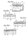
- the pipe joint of the present invention covers a pipe joint of the coupling type shown in Fig. 3(a) and that of the integral type shown in Figs. 3(b), 3(c), and 3(d).
- a lip portion which constitutes a metal sealing portion on an externally-threaded member is provided.
- a metal-plated or resin-coated layer may also be provided on a lip portion of at least the outer end, i.e., the lip portion side of the externally-threaded member. Needless to say, this means that the layer may be provided on both the metal sealing portions at the lip portion side and the bottom portion side of the externally-threaded member. But, as already mentioned, the galling resistant layer is not provided on the internally-threaded member.
- FIG. 3(a) shows a pipe joint of the coupling type 20 of the present invention partially in cross section.
- a pipe 21 is provided with an external thread 22, and a lip portion 23 is also provided at the lip portion side of the externally-threaded member 24.
- the tip of the lip portion 23 is an edge face 25 of the pipe 21.
- Another pipe 26 constituting an internally-threaded member 27 is provided with an internal thread 28, and a cylindrical, thread-free inner surface 29 is provided at the bottom portion side of the internally-threaded member 27.
- the cylindrical, thread-free inner surface 29 corresponds to the outer surface of the lip portion 23.
- the edge of the inner surface 29 is a shoulder portion corresponding to the edge face 25 of the lip portion 23.
- the thread-free outer peripheral surface 23 and the thread-free inner surface 29 are tapered.
- the contacting area of the outer peripheral surface 23 of the lip portion with the thread-free inner surface 29 and the contacting area of the edge face 25 with the shoulder portion constitute metal sealing portions.
- the former contacting area constitutes a main sealing portion and the latter constitutes a sub-sealing portion. Both of the sealing portions are referred to as the metal sealing portion in this specification.
- Figs. 3(b) through 3(d) show an integral-type pipe joint of the present invention.
- Fig. 3(b) shows a pipe joint similar to that of Fig. 3(a) having a thread-free outer surface 23, although the pipe joint shown in Fig. 3(b) is of the integral type.
- Fig. 3(c) shows another case, in which two thread-free outer peripheral surfaces 23 and 31 at the outer and inner ends, i.e., at a metal sealing lip portion and a metal sealing bottom portion are provided. The metal sealing bottom portion 31 terminates at a shoulder portion 32.
- Fig. 3(d) shows a case similar to that of Fig. 3(c) except that the wall thickness of the pipe joint portion is substantially the same throughout its length.
- the galling-resistant layer is provided not only on the lip ,portion 23 and the root portion 32 but also on the edge face 25 and the shoulder portion 32 of the externally-threaded member.
- the cylindrical outer surface 23 of at least the lip portion of pipe 21 only, namely externally-threaded member 24 only is provided with a metal-plated layer exhibiting improved resistance to abrasion or a resin-coated layer exhibiting improved heat and abrasion resistance.
- the amount of abrasion of the metal-plated layer or resin-coated layer is very small, and there is no galling whatsoever after one cycle of connecting and disconnecting.
- the above layer is substantially free from galling after ten cycles of repeated connecting and disconnecting.
- a metal plating or resin coating layer is provided on the cylindrical outer surface 23 of at least the lip portion of the externally-threaded member 24.
- the outer surface 23 is the area least subject to galling. It is to be noted that essentially it is only the externally-threaded member on which the metal-plated or resin-coated layer is provided, and that at least the outer surface 23 of the lip portion should be provided with the above abrasion-resistant layer.
- Such a galling resistant layer may of course be provided on the edge face 25 as well as on the outer peripheral surface 23.
- Fig. 5 shows the case in which a cap cell 40 is placed surrounding the outer surface 23 of a lip portion and the external thread 22 to carry out metal plating.
- the cap cell 40 has a hollow sealing sleeve 42 at its open end.
- a projection 44 is provided on an inner wall of the cap cell 40 in order to prevent a plating solution from flowing into the inner side the pipe.
- Reference numeral 46 indicates an annular electrode, 47 an inlet for a plating solution, 48 an outlet, 49 a tank, and "P" indicates a pump.
- the process of carrying out the plating is the same as usual electroplating, and therefore a detailed description will be omitted.
- an area which is not desired to be metal plated e. g., an external thread 22 is preferably covered beforehand with some material which is inert to the metal plating.
- material for producing an oil well pipe are low alloy steels, Cr-Mo steels containing a few per cent of chromium and molybdenum or the like.
- a high chromium steel containing 10% or more of Cr, and preferably a high alloy steel containing 10% ⁇ Cr + Ni + Mo ⁇ _ 95% is used.
- an activating layer is preferably provided on the outer surface by means of placing the outer surface in an aqueous acid solution containing chloride ions, then subjecting the surface to an anodic electrolytic treatment, then switching to a cathodic electrolytic treatment to deposit a metal selected from the group consisting of iron, nickel, zinc, cobalt, copper, manganese and chromium, and alloys thereof.
- a metal selected from the group consisting of iron, nickel, zinc, cobalt, copper, manganese and chromium, and alloys thereof.
- the solid lubricating particles are preferably added in an amount of 5 - 40% by volume.
- the undercoating of a soft metal is preferably of copper, zinc, tin, or lead, and the total thickness of the metal-plated layer is preferably 15 - 40 ⁇ m.
- the thickness of the uppermost coating is over one-half the total thickness, the resulting layer becomes so hard that plastic deformation and energy absorption caused thereby is insufficient.
- an additional metal-plated layer such as the above-mentioned activating layer, an intermediate plated layer, or the like may be applied.
- the deformation stress applied to the uppermost coating is absorbed by the underlying soft metal layer. Peeling off of the uppermost coating is successfully prevented. If the uppermost coating breaks while connnecting the oil well pipe joint, the broken pieces of the coating do not peel off, but are imbedded in the underlying coating.
- a sublayer of a metal selected from the group consisting of Cu, Sn, Pb, and alloys thereof may preferably be provided so as to improve the resistance to galling.
- Fig. 6 shows the process for applying a resin-coated layer onto the outer surface of the lip portion.
- a resin solution is sprayed through a nozzle 50 onto the outer surface 23 of the lip portion of the pipe 21.
- An external thread 22 is previously covered with some material which is inert to spray coating so that the resin is not placed on the external thread.
- the layer may be dried in an oven (not shown). In this case the pipe 21 may be kept in the horizontal position while it is treated.
- a resin coating is dielectric, so it does not constitute a local cell even when it contacts a metal. Therefore, the coating layer does not cause an acceleration in the corrosion of the substrate.
- the resin since the resin is a polymeric substance, it does not decompose or degrade.
- a resin-coated layer which can exhibit improved resistance to corrosion and galling under severe corrosive conditions which are frequently experienced in deep oil wells is preferably applied as follows:
- the abrasion test was carried out as follows:
- the pin-type test piece and the plate-type test piece were rubbed together and the number of slides before galling occurred was determined. The amount of particles which were worn away before galling occurred was also determined.
- the surface of the plate-type test piece was sand-blasted or shot-blasted and was free from such a resin coating.
- the surface roughness was 15 pm R max and the thickness of the coating was 10 ⁇ m.
- the test results are graphed in Figs. 7 - 13.
- the resistance to galling was determined by the number of slides, i.e., the number of repetitions before galling occurred.
- Fig. 7 shows the case where the resin-coated layer was a lower polymeric epoxy resin (low molecular weight epoxy resin, molecular weight approx. 20,000) layer containing 0 - 50% by weight of polytetrafluoroethylene (“PTFE" hereunder) particles (0.5 ⁇ m in diameter).
- PTFE polytetrafluoroethylene
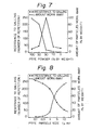
- Fig. 8 is a graph showing galling resistance plotted against the particle size of the polytetrafluoroethylene particles for the case in which the coating resin was a low molecular weight epoxy resin and the amount of the particle incorporated was 30% by weight.
- the particle diameter is preferably 1 ⁇ m or smaller.
- Fig. 9 is a graph similar to Fig. 7, in which various resins were used as a coating layer in which various amounts of polytetrafluoroethylene particles were incorporated.
- the matrix resin was a silicone resin (m.w. approx. 2,000), a low m. w. epoxy resin (m.w. approx. 20,000), and polyethylene sulfone.
- Fig. 10 is a graph of the test results plotted against the surface roughness of a pin-type test piece ranging from 2 ⁇ m R max to 3 5 ,u m R max
- the thickness of the resin-coated layer of said low m. w. epoxy resin was 3 ⁇ m, 5 um, 10 ⁇ m, 20 ⁇ m, 25 ⁇ m, and 30 ⁇ m.
- the particle incorporated was PTFE 0.5 ⁇ m in diameter in an amount of 30% by weight.
- the surface roughness is preferably 5 - 25 ⁇ m R max ⁇ It is to be noted that the resistance to galling is noticeable when the surface roughness is larger than the thickness of the coating layer, i.e., when the thickness is smaller than the surface roughness. This means that the thickness of the coating resin is closely related to surface roughness of the coating resin layer, and that the surface of the coating resin layer should be so thin that the roughness thereof can reflect from the surface roughness of the substrate to some extent. Thus, the remaining roughness on the resin-coated layer surface may maintain a thread compound in recesses on the uneven surface during connecting and disconnecting in practice, resulting in good lubricating properties.
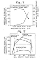
- Fig. 11 test results are plotted against the MoS 2 particle size.
- MoS 2 particles in an amount of 70% by weight were incorporated in a low molecular weight epoxy resin (m.w. approx. 20,000). It is apparent from Fig. 11 that the resistance to galling is markedly deteriorated and the amount of particles which are worn way increases when the particle size increases over 10 ⁇ m.
- the particle diameter of MoS 2 is 10 pm or less, preferably 3 - 10 ⁇ m.
- Fig. 12 is a graph showing the relationship between the resistance to galling and the content of MoS 2 particles in a resin coating layer.
- the resins employed were the same as in Fig. 9.
- the particle size of the MoS 2 particle was 6 ⁇ m on the average, ranging from 3 ⁇ m to 10 ⁇ m.
- the content of MoS 2 is preferably 20 - 90% by weight, and more preferably it is 40 - 70% by weight.
- Fig. 13 is a graph similar to Fig. 10, in which the relationship between the surface roughness and the resistance to galling is shown.
- the resin layer was a low molecular weight epoxy resin (m.w. approx. 20,000) containing 70% by weight of MoS 2 particles having an average particle diameter of 6 ⁇ m. The same tendency as in Fig. 10 can be seen in Fig. 13.
- a series of working examples of the present invention were carried out using an oil well pipe joint of the coupling type shown in Fig. 3(a).
- the pipe joints were manufactured in a conventional manner. Only the thread-free, outer peripheral surface of the metal sealing portion of the externally-threaded member, i. e., the lip portion 23 of Fig. 3(a) was provided with a galling resistant layer in accordance with the present invention. Not only the surfaces -to be treated in accordance with the present invention, but also the inner surfaces of the metal sealing portions of the internally-threaded member were subjected to surface forming with shot blasting or machining.
- the pipe joints were subjected to a power tight test by which the number of connecting and disconnecting cycles achieved before galling occurred was determined.
- the power tight test was carried out at a screw revolution speed of 0.5 r.p.m..
- Example 1 shows Example 1, in which the galling-resistant layer was a metal plating of a soft metal such as copper and tin.
- Test Run No.4 shows the case in which the thickness of the metal plating was much thinner than that usually requirec in the present invention.
- Example 2 shows Example 2, in which the metal plating layer comprised an uppermost coating of Cr and an undercoating of a soft metal. Comparative Examples 1 - 3 are the same as those in Example 1.
- Table 3 shows Example 3, in which a composite metal plating was carried out.
- Table 4 shows Example 4, in which the metal plating comprised a precious metal such as gold and an alloy thereof.
- the metal plating comprised a precious metal such as gold and an alloy thereof.
- an undercoating of a soft metal was provided.
- Test Runs Nos. 4 and 5 show that the provision of such a metal plating on the metal sealing portion of the internally-threaded member is not enough to exhibit improved resistance to galling.
- Table 5 shows the resistance to galling before and after corrosion test for the pipe joint of Example 4.
- Table 6 shows Example 5, in which a resin coating containing PTFE or MoS 2 particles as solid lubricating agents was placed on the lip portion of the externally-threaded member.
- an oil well pipe joint can be produced which is free from galling even after more than 10 repeated connecting and disconnecting cycles under severe corrosive conditions.
Landscapes
- Engineering & Computer Science (AREA)
- General Engineering & Computer Science (AREA)
- Mechanical Engineering (AREA)
- Life Sciences & Earth Sciences (AREA)
- Geology (AREA)
- Mining & Mineral Resources (AREA)
- Physics & Mathematics (AREA)
- Environmental & Geological Engineering (AREA)
- Fluid Mechanics (AREA)
- General Life Sciences & Earth Sciences (AREA)
- Geochemistry & Mineralogy (AREA)
- Non-Disconnectible Joints And Screw-Threaded Joints (AREA)
Applications Claiming Priority (2)
| Application Number | Priority Date | Filing Date | Title |
|---|---|---|---|
| JP59062629A JPS60205091A (ja) | 1984-03-29 | 1984-03-29 | 油井管用管継手 |
| JP62629/84 | 1984-03-29 |
Publications (3)
| Publication Number | Publication Date |
|---|---|
| EP0157587A2 true EP0157587A2 (fr) | 1985-10-09 |
| EP0157587A3 EP0157587A3 (en) | 1986-11-26 |
| EP0157587B1 EP0157587B1 (fr) | 1989-04-19 |
Family
ID=13205802
Family Applications (1)
| Application Number | Title | Priority Date | Filing Date |
|---|---|---|---|
| EP85302118A Expired EP0157587B1 (fr) | 1984-03-29 | 1985-03-26 | Raccord de conduits pour puits pétrolifères |
Country Status (5)
| Country | Link |
|---|---|
| US (1) | US4630849A (fr) |
| EP (1) | EP0157587B1 (fr) |
| JP (1) | JPS60205091A (fr) |
| CA (1) | CA1238352A (fr) |
| DE (1) | DE3569598D1 (fr) |
Cited By (14)
| Publication number | Priority date | Publication date | Assignee | Title |
|---|---|---|---|---|
| EP0264446A4 (fr) * | 1986-05-02 | 1988-08-17 | Sumitomo Metal Ind | Joint pour canalisations de puits de petrole et methode pour sa fabrication. |
| DE3805512A1 (de) * | 1987-02-23 | 1988-09-08 | Nippon Steel Corp | Gewindeverbindung fuer oelbohrrohr |
| GB2219022B (en) * | 1986-09-19 | 1990-08-15 | Roy L Dudman | High bending strength ratio drill string components |
| EP0393802A3 (fr) * | 1989-04-19 | 1991-04-17 | MANNESMANN Aktiengesellschaft | Procédé de traitement préparatoire d'éléments de connexion d'un raccord de tuyaux étanche au gaz |
| EP0574102A1 (fr) * | 1992-06-09 | 1993-12-15 | MANNESMANN Aktiengesellschaft | Procédé de traitement préparatoire pour les éléments d'un raccord de tuyaux étanche aux gaz |
| EP0632225A1 (fr) * | 1993-06-30 | 1995-01-04 | AGIP S.p.A. | Protection anti-grippage pour des raccords, adapté notamment pour le secteur de pétrole |
| US5769466A (en) * | 1994-10-13 | 1998-06-23 | Vallourec Oil & Gas | Threaded joint for pipes |
| GB2356230A (en) * | 1999-09-21 | 2001-05-16 | Siderca Sa Ind Y Com | A threaded connection |
| JP2004507698A (ja) * | 2000-08-31 | 2004-03-11 | バローレック・マネスマン・オイル・アンド・ガス・フランス | 耐摩損性のねじ管接ぎ手用ねじ機素 |
| RU2301726C2 (ru) * | 2005-07-04 | 2007-06-27 | ОАО "Челябинский трубопрокатный завод" | Способ нарезания упорной резьбы "баттресс" на концевых участках обсадных труб и соединительных муфт |
| EP2059704A4 (fr) * | 2006-09-14 | 2011-05-25 | Sumitomo Metal Ind | Joint fileté pour tuyaux en acier |
| AT516684A1 (de) * | 2015-01-13 | 2016-07-15 | Voestalpine Tubulars Gmbh & Co Kg | Lösbare Gewindeverbindung mit asymmetrischer Beschichtung |
| CN116480857A (zh) * | 2023-05-09 | 2023-07-25 | 大庆市恒顺化工有限公司 | 用于酸性油气田开发的复合防腐蚀油气井管及其制备方法 |
| CN109372442B (zh) * | 2018-11-26 | 2024-06-11 | 中国石油大学(北京) | 防腐油管的补口工艺方法、防腐油管及其单元 |
Families Citing this family (93)
| Publication number | Priority date | Publication date | Assignee | Title |
|---|---|---|---|---|
| FR2571467B1 (fr) * | 1984-10-10 | 1987-03-20 | Vallourec | Joint filete pour tube d'acier comportant un dispositif d'etancheite au niveau des filetages |
| FR2592935B1 (fr) * | 1986-01-15 | 1988-04-15 | Vallourec | Joint filete composite pour tube d'acier |
| SE460301B (sv) * | 1986-10-15 | 1989-09-25 | Sandvik Ab | Skarvstaang foer slaaende bergborrmaskin |
| JPS63293384A (ja) * | 1987-05-27 | 1988-11-30 | 住友金属工業株式会社 | ねじ継手付frp管 |
| JPH01199088A (ja) * | 1988-02-03 | 1989-08-10 | Nippon Steel Corp | 耐隙間腐食性に優れた高合金油井管用継手 |
| IT1272733B (it) * | 1993-10-19 | 1997-06-26 | Agip Spa | Giunzione integrale perfezionata di due tubazioni |
| US6027145A (en) * | 1994-10-04 | 2000-02-22 | Nippon Steel Corporation | Joint for steel pipe having high galling resistance and surface treatment method thereof |
| US6030004A (en) * | 1997-12-08 | 2000-02-29 | Shaw Industries | High torque threaded tool joint for drill pipe and other drill stem components |
| AU6981001A (en) | 1998-11-16 | 2002-01-02 | Shell Oil Co | Radial expansion of tubular members |
| US7357188B1 (en) | 1998-12-07 | 2008-04-15 | Shell Oil Company | Mono-diameter wellbore casing |
| US6712154B2 (en) * | 1998-11-16 | 2004-03-30 | Enventure Global Technology | Isolation of subterranean zones |
| US6823937B1 (en) | 1998-12-07 | 2004-11-30 | Shell Oil Company | Wellhead |
| US6557640B1 (en) | 1998-12-07 | 2003-05-06 | Shell Oil Company | Lubrication and self-cleaning system for expansion mandrel |
| US7231985B2 (en) | 1998-11-16 | 2007-06-19 | Shell Oil Company | Radial expansion of tubular members |
| US7168496B2 (en) | 2001-07-06 | 2007-01-30 | Eventure Global Technology | Liner hanger |
| US7603758B2 (en) | 1998-12-07 | 2009-10-20 | Shell Oil Company | Method of coupling a tubular member |
| US6634431B2 (en) * | 1998-11-16 | 2003-10-21 | Robert Lance Cook | Isolation of subterranean zones |
| US7121352B2 (en) | 1998-11-16 | 2006-10-17 | Enventure Global Technology | Isolation of subterranean zones |
| US6745845B2 (en) * | 1998-11-16 | 2004-06-08 | Shell Oil Company | Isolation of subterranean zones |
| US7195064B2 (en) | 1998-12-07 | 2007-03-27 | Enventure Global Technology | Mono-diameter wellbore casing |
| US7185710B2 (en) | 1998-12-07 | 2007-03-06 | Enventure Global Technology | Mono-diameter wellbore casing |
| GB2344606B (en) | 1998-12-07 | 2003-08-13 | Shell Int Research | Forming a wellbore casing by expansion of a tubular member |
| US7552776B2 (en) | 1998-12-07 | 2009-06-30 | Enventure Global Technology, Llc | Anchor hangers |
| US6739392B2 (en) * | 1998-12-07 | 2004-05-25 | Shell Oil Company | Forming a wellbore casing while simultaneously drilling a wellbore |
| US7363984B2 (en) | 1998-12-07 | 2008-04-29 | Enventure Global Technology, Llc | System for radially expanding a tubular member |
| CA2310878A1 (fr) | 1998-12-07 | 2000-12-07 | Shell Internationale Research Maatschappij B.V. | Systeme de lubrification et d'autonettoyage pour mandrin expansible |
| AU770359B2 (en) | 1999-02-26 | 2004-02-19 | Shell Internationale Research Maatschappij B.V. | Liner hanger |
| US7055608B2 (en) | 1999-03-11 | 2006-06-06 | Shell Oil Company | Forming a wellbore casing while simultaneously drilling a wellbore |
| CA2306656C (fr) | 1999-04-26 | 2006-06-06 | Shell Internationale Research Maatschappij B.V. | Connexion extensible |
| US7350563B2 (en) | 1999-07-09 | 2008-04-01 | Enventure Global Technology, L.L.C. | System for lining a wellbore casing |
| US7048067B1 (en) | 1999-11-01 | 2006-05-23 | Shell Oil Company | Wellbore casing repair |
| US7234531B2 (en) | 1999-12-03 | 2007-06-26 | Enventure Global Technology, Llc | Mono-diameter wellbore casing |
| US7516790B2 (en) | 1999-12-03 | 2009-04-14 | Enventure Global Technology, Llc | Mono-diameter wellbore casing |
| US7100684B2 (en) | 2000-07-28 | 2006-09-05 | Enventure Global Technology | Liner hanger with standoffs |
| WO2002023007A1 (fr) | 2000-09-18 | 2002-03-21 | Shell Oil Company | Suspension de colonne perdue comprenant une soupape a manchon |
| US7100685B2 (en) | 2000-10-02 | 2006-09-05 | Enventure Global Technology | Mono-diameter wellbore casing |
| GB2389597B (en) | 2000-10-02 | 2005-05-18 | Shell Oil Co | Plastically deforming and radially expanding a tubular member |
| JP4092871B2 (ja) * | 2000-12-04 | 2008-05-28 | 住友金属工業株式会社 | ねじ継手の潤滑処理に適した潤滑被膜形成用組成物 |
| CA2428819A1 (fr) | 2001-01-03 | 2002-07-11 | Enventure Global Technology | Cuvelage de diametre nanometrique pour puits fore |
| US7410000B2 (en) | 2001-01-17 | 2008-08-12 | Enventure Global Technology, Llc. | Mono-diameter wellbore casing |
| JP3931564B2 (ja) * | 2001-01-25 | 2007-06-20 | 住友金属工業株式会社 | 耐焼付き性及び防錆性に優れた鋼管用ねじ継手 |
| WO2002084162A1 (fr) * | 2001-04-11 | 2002-10-24 | Sumitomo Metal Industries, Ltd. | Joint filete pour tuyau en acier |
| US6672594B2 (en) * | 2001-05-21 | 2004-01-06 | Dana Corporation | High temperature coating of exhaust components |
| CA2453034C (fr) | 2001-07-06 | 2010-09-14 | Enventure Global Technology | Suspension de colonne perdue |
| JP3870732B2 (ja) * | 2001-07-25 | 2007-01-24 | 住友金属工業株式会社 | 耐焼付き性に優れた鋼管用ねじ継手 |
| US7258168B2 (en) | 2001-07-27 | 2007-08-21 | Enventure Global Technology L.L.C. | Liner hanger with slip joint sealing members and method of use |
| CA2459910C (fr) | 2001-09-07 | 2010-04-13 | Enventure Global Technology | Ensemble cone d'expansion reglable |
| AU2002360373A1 (en) | 2001-11-12 | 2003-05-26 | Enventure Global Technlogy | Mono diameter wellbore casing |
| GB0130967D0 (en) | 2001-12-24 | 2002-02-13 | Hunting Oilfield Services Ltd | Anti galling threaded joint |
| AU2002367348A1 (en) | 2001-12-27 | 2003-07-24 | Enventure Global Technology | Seal receptacle using expandable liner hanger |
| US7377326B2 (en) | 2002-08-23 | 2008-05-27 | Enventure Global Technology, L.L.C. | Magnetic impulse applied sleeve method of forming a wellbore casing |
| US7424918B2 (en) | 2002-08-23 | 2008-09-16 | Enventure Global Technology, L.L.C. | Interposed joint sealing layer method of forming a wellbore casing |
| ATE327409T1 (de) * | 2002-03-08 | 2006-06-15 | Grant Prideco Lp | Mit doppelten schultern ausgestattene verbindung für ölfeldrohre |
| EP1985796B1 (fr) | 2002-04-12 | 2012-05-16 | Enventure Global Technology | Manchon protecteur pour connexions filetées pour support de conduite extensible |
| EP1501645A4 (fr) | 2002-04-15 | 2006-04-26 | Enventure Global Technology | Manchon protecteur destine aux connexions filetees d'un dispositif de suspension pour colonne de tubage perdue expansible |
| ITRM20020234A1 (it) * | 2002-04-30 | 2003-10-30 | Tenaris Connections Bv | Giunzione filettata per tubi. |
| GB2426993B (en) | 2002-05-29 | 2007-05-02 | Enventure Global Technology | System for radially expanding a tubular member |
| AU2003241890A1 (en) * | 2002-05-31 | 2003-12-19 | Sumitomo Metal Industries, Ltd. | Screw joint for steel pipe |
| WO2003104601A2 (fr) | 2002-06-10 | 2003-12-18 | Enventure Global Technology | Tubage de puits de forage a un seul diametre |
| JP3733529B2 (ja) * | 2002-08-16 | 2006-01-11 | 株式会社メタルワン | パイプのネジ継手構造およびパイプのネジ継手方法 |
| KR100459432B1 (ko) * | 2002-08-21 | 2004-12-03 | 엘지전자 주식회사 | 이동통신 시스템의 핸드오버 처리방법 |
| WO2004027392A1 (fr) | 2002-09-20 | 2004-04-01 | Enventure Global Technology | Evaluation de formabilite de conduite pour des elements tubulaires extensibles |
| AU2003270774A1 (en) | 2002-09-20 | 2004-04-08 | Enventure Global Technlogy | Bottom plug for forming a mono diameter wellbore casing |
| GB2410280B (en) | 2002-09-20 | 2007-04-04 | Enventure Global Technology | Self-lubricating expansion mandrel for expandable tubular |
| AU2003263859A1 (en) | 2002-09-20 | 2004-04-08 | Enventure Global Technology | Protective sleeve for expandable tubulars |
| ITRM20020512A1 (it) * | 2002-10-10 | 2004-04-11 | Tenaris Connections Bv | Tubo filettato con trattamento superficiale. |
| US7886831B2 (en) | 2003-01-22 | 2011-02-15 | Enventure Global Technology, L.L.C. | Apparatus for radially expanding and plastically deforming a tubular member |
| GB2433281B (en) | 2003-01-27 | 2007-08-01 | Enventure Global Technology | Lubrication system for radially expanding tubular members |
| ITRM20030065A1 (it) | 2003-02-13 | 2004-08-14 | Tenaris Connections Bv | Giunzione filettata per tubi. |
| GB2415983B (en) | 2003-02-26 | 2007-09-05 | Enventure Global Technology | Apparatus for radially expanding and plastically deforming a tubular member |
| US20040174017A1 (en) * | 2003-03-06 | 2004-09-09 | Lone Star Steel Company | Tubular goods with expandable threaded connections |
| GB2415454B (en) | 2003-03-11 | 2007-08-01 | Enventure Global Technology | Apparatus for radially expanding and plastically deforming a tubular member |
| GB2415988B (en) | 2003-04-17 | 2007-10-17 | Enventure Global Technology | Apparatus for radially expanding and plastically deforming a tubular member |
| US7169239B2 (en) | 2003-05-16 | 2007-01-30 | Lone Star Steel Company, L.P. | Solid expandable tubular members formed from very low carbon steel and method |
| US20050166387A1 (en) | 2003-06-13 | 2005-08-04 | Cook Robert L. | Method and apparatus for forming a mono-diameter wellbore casing |
| US7712522B2 (en) | 2003-09-05 | 2010-05-11 | Enventure Global Technology, Llc | Expansion cone and system |
| JP4599874B2 (ja) * | 2004-04-06 | 2010-12-15 | 住友金属工業株式会社 | 油井管用ねじ継手、及びその製造方法 |
| CA2577083A1 (fr) | 2004-08-13 | 2006-02-23 | Mark Shuster | Dispositif d'expansion d'elements tubulaires |
| US20090101328A1 (en) | 2004-09-28 | 2009-04-23 | Advanced Composite Products & Technology, Inc. | Composite drill pipe and method of forming same |
| US7458617B2 (en) * | 2004-09-28 | 2008-12-02 | Advanced Composite Products & Technology, Inc. | Composite drill pipe |
| FR2892174B1 (fr) | 2005-10-14 | 2007-12-28 | Vallourec Mannesmann Oil Gas F | Element filete tubulaire muni d'un revetement protecteur sec |
| MX2009011010A (es) | 2007-04-13 | 2009-10-30 | Vallourec Mannesmann Oil & Gas | Elemento roscado tubular provisto de un revestimiento protector seco. |
| JP4429347B2 (ja) * | 2007-09-18 | 2010-03-10 | 富士通テン株式会社 | ミリ波レーダ装置のバイアス調整方法 |
| AR076167A1 (es) * | 2009-03-30 | 2011-05-26 | Sumitomo Metal Ind | Aparato y metodo para la aplicacion de un lubricante a una porcion roscada de una tuberia de acero |
| CA2808597C (fr) * | 2010-08-31 | 2017-05-09 | Nippon Steel & Sumitomo Metal Corporation | Appareil de revetement permettant d'appliquer une resine durcissable aux uv a une extremite filetee d'un tuyau en acier |
| WO2014095836A1 (fr) * | 2012-12-20 | 2014-06-26 | Shell Internationale Research Maatschappij B.V. | Raccord de tuyau et procédé associé |
| FR3011309B1 (fr) * | 2013-10-02 | 2015-10-30 | Vallourec Oil & Gas France | Butee pour un composant tubulaire recouverte d'un depot metallique composite |
| US9857005B2 (en) | 2014-01-10 | 2018-01-02 | Wright's Well Control Services, Llc | Fluid connector assembly and method of establishing a fluid connection |
| US9470044B1 (en) | 2015-07-06 | 2016-10-18 | Pegasis S.r.l. | Threaded connection having high galling resistance and method of making same |
| US10342958B2 (en) | 2017-06-30 | 2019-07-09 | Abbott Cardiovascular Systems Inc. | System and method for correcting valve regurgitation |
| WO2019074103A1 (fr) * | 2017-10-13 | 2019-04-18 | 新日鐵住金株式会社 | Joint fileté pour tuyaux et procédé de production d'un joint fileté pour tuyaux |
| CN109132246B (zh) * | 2018-08-30 | 2023-07-04 | 浙江科赛新材料科技有限公司 | 油罐接头 |
| EP4477932A4 (fr) * | 2022-02-10 | 2025-06-11 | Nippon Steel Corporation | Tuyau métallique pour puits de pétrole |
Family Cites Families (19)
| Publication number | Priority date | Publication date | Assignee | Title |
|---|---|---|---|---|
| US1141151A (en) * | 1914-06-06 | 1915-06-01 | Nat Tube Co | Pipe-coupling. |
| US3627561A (en) * | 1965-07-16 | 1971-12-14 | Owens Illinois Inc | Process for bonding platinum onto a base metal |
| US3869393A (en) * | 1970-05-21 | 1975-03-04 | Everlube Corp Of America | Solid lubricant adhesive film |
| US3716348A (en) * | 1970-06-01 | 1973-02-13 | G Perkins | Method of forming abrasion-resistant self-lubricating coating on ferrous metals and aluminum and resulting articles |
| JPS5211765B2 (fr) * | 1972-03-31 | 1977-04-02 | ||
| US4049861A (en) * | 1975-03-07 | 1977-09-20 | Minnesota Mining And Manufacturing Company | Abrasion resistant coatings |
| US4113914A (en) * | 1977-05-09 | 1978-09-12 | Phillips Petroleum Company | Process for applying sealant composition |
| JPS5945872B2 (ja) * | 1978-10-13 | 1984-11-09 | 旭硝子株式会社 | パツキング付継手 |
| JPS56113383A (en) * | 1980-02-12 | 1981-09-07 | Toyo Kohan Co Ltd | Production of metal article coated with composite resin layer excellent in corrosion resistance |
| US4384737A (en) * | 1980-04-25 | 1983-05-24 | Republic Steel Corporation | Threaded joint for well casing and tubing |
| JPS6057519B2 (ja) * | 1981-08-20 | 1985-12-16 | 住友金属工業株式会社 | 耐焼付性に優れた油井管継手およびその製造方法 |
| ATE18788T1 (de) * | 1982-01-12 | 1986-04-15 | Stroedter Wilhelm Masch | Schutzkappe und schutznippel fuer oelfeldrohre. |
| DE3203857C2 (de) * | 1982-02-03 | 1984-08-02 | Mannesmann AG, 4000 Düsseldorf | Ölfeldrohr-Verbindung und Verfahren zum Verbinden von Ölfeld-Rohren |
| DE3218145A1 (de) * | 1982-05-14 | 1983-11-24 | Daimler-Benz Ag, 7000 Stuttgart | Verfahren zur erhoehung der lebensdauer und verringerung der reibung von oelgeschmierten kegelrollenlagern |
| US4527815A (en) * | 1982-10-21 | 1985-07-09 | Mobil Oil Corporation | Use of electroless nickel coating to prevent galling of threaded tubular joints |
| DE3243340C2 (de) * | 1982-11-19 | 1985-02-21 | Mannesmann AG, 4000 Düsseldorf | Gewinderohrverbindung für die Erdöl- und Erdgasgewinnung |
| US4538840A (en) * | 1983-01-03 | 1985-09-03 | Delange Richard W | Connector means for use on oil and gas well tubing or the like |
| GB2140117B (en) * | 1983-05-17 | 1986-11-05 | Boc Nowsco Ltd | Screw-thread protection |
| US4506432A (en) * | 1983-10-03 | 1985-03-26 | Hughes Tool Company | Method of connecting joints of drill pipe |
-
1984
- 1984-03-29 JP JP59062629A patent/JPS60205091A/ja active Pending
-
1985
- 1985-03-25 CA CA000477362A patent/CA1238352A/fr not_active Expired
- 1985-03-26 DE DE8585302118T patent/DE3569598D1/de not_active Expired
- 1985-03-26 EP EP85302118A patent/EP0157587B1/fr not_active Expired
- 1985-03-27 US US06/716,765 patent/US4630849A/en not_active Expired - Fee Related
Cited By (21)
| Publication number | Priority date | Publication date | Assignee | Title |
|---|---|---|---|---|
| EP0264446A4 (fr) * | 1986-05-02 | 1988-08-17 | Sumitomo Metal Ind | Joint pour canalisations de puits de petrole et methode pour sa fabrication. |
| GB2219022B (en) * | 1986-09-19 | 1990-08-15 | Roy L Dudman | High bending strength ratio drill string components |
| DE3805512A1 (de) * | 1987-02-23 | 1988-09-08 | Nippon Steel Corp | Gewindeverbindung fuer oelbohrrohr |
| EP0393802A3 (fr) * | 1989-04-19 | 1991-04-17 | MANNESMANN Aktiengesellschaft | Procédé de traitement préparatoire d'éléments de connexion d'un raccord de tuyaux étanche au gaz |
| EP0574102A1 (fr) * | 1992-06-09 | 1993-12-15 | MANNESMANN Aktiengesellschaft | Procédé de traitement préparatoire pour les éléments d'un raccord de tuyaux étanche aux gaz |
| EP0632225A1 (fr) * | 1993-06-30 | 1995-01-04 | AGIP S.p.A. | Protection anti-grippage pour des raccords, adapté notamment pour le secteur de pétrole |
| US5678608A (en) * | 1993-06-30 | 1997-10-21 | Agip S.P.A. | Anti-seizure protection for joints, particularly suitable for the petroleum sector |
| CN1037025C (zh) * | 1993-06-30 | 1998-01-14 | 阿吉普公司 | 改进的特别适合于石油行业的接头处抗咬住保护 |
| US5769466A (en) * | 1994-10-13 | 1998-06-23 | Vallourec Oil & Gas | Threaded joint for pipes |
| GB2356230B (en) * | 1999-09-21 | 2003-10-15 | Siderca Sa Ind Y Com | A threaded union highly resistant to overtorque and compression |
| GB2356230A (en) * | 1999-09-21 | 2001-05-16 | Siderca Sa Ind Y Com | A threaded connection |
| JP2004507698A (ja) * | 2000-08-31 | 2004-03-11 | バローレック・マネスマン・オイル・アンド・ガス・フランス | 耐摩損性のねじ管接ぎ手用ねじ機素 |
| JP4860892B2 (ja) * | 2000-08-31 | 2012-01-25 | バローレック・マネスマン・オイル・アンド・ガス・フランス | 耐摩損性のねじ管接ぎ手用ねじ機素 |
| RU2301726C2 (ru) * | 2005-07-04 | 2007-06-27 | ОАО "Челябинский трубопрокатный завод" | Способ нарезания упорной резьбы "баттресс" на концевых участках обсадных труб и соединительных муфт |
| EP2059704A4 (fr) * | 2006-09-14 | 2011-05-25 | Sumitomo Metal Ind | Joint fileté pour tuyaux en acier |
| US8857857B2 (en) | 2006-09-14 | 2014-10-14 | Nippon Steel & Sumitomo Metal Corporation | Threaded joint for steel pipes |
| AT516684A1 (de) * | 2015-01-13 | 2016-07-15 | Voestalpine Tubulars Gmbh & Co Kg | Lösbare Gewindeverbindung mit asymmetrischer Beschichtung |
| AT516684B1 (de) * | 2015-01-13 | 2018-08-15 | Voestalpine Tubulars Gmbh & Co Kg | Lösbare Gewindeverbindung mit asymmetrischer Beschichtung |
| US11105457B2 (en) | 2015-01-13 | 2021-08-31 | Voestalpine Tubulars Gmbh & Co Kg | Separable threaded connection with asymmetric coating |
| CN109372442B (zh) * | 2018-11-26 | 2024-06-11 | 中国石油大学(北京) | 防腐油管的补口工艺方法、防腐油管及其单元 |
| CN116480857A (zh) * | 2023-05-09 | 2023-07-25 | 大庆市恒顺化工有限公司 | 用于酸性油气田开发的复合防腐蚀油气井管及其制备方法 |
Also Published As
| Publication number | Publication date |
|---|---|
| EP0157587B1 (fr) | 1989-04-19 |
| US4630849A (en) | 1986-12-23 |
| DE3569598D1 (en) | 1989-05-24 |
| CA1238352A (fr) | 1988-06-21 |
| EP0157587A3 (en) | 1986-11-26 |
| JPS60205091A (ja) | 1985-10-16 |
Similar Documents
| Publication | Publication Date | Title |
|---|---|---|
| US4630849A (en) | Oil well pipe joint | |
| EP2128506B1 (fr) | Joint à vis pour tuyau en acier | |
| JP6050302B2 (ja) | 表面コーティングを有する楔形ねじ山を備える管状接合部 | |
| EP1411288A1 (fr) | Joint filete pour tube d'acier | |
| EP0786616A1 (fr) | Union de tuyaux d'acier presentant une resistance elevee au grippage et traitement de surface destine a cet effet | |
| EP1920180B1 (fr) | Assemblage vissé pour tuyaux en acier | |
| EA035552B1 (ru) | Резьбовой трубный элемент, обеспеченный металлическим противокоррозионным и противозадирным покрытием | |
| EP1458908B1 (fr) | Element tubulaire presentant un revetement anti-eraillure$i( ) | |
| EP4206511B1 (fr) | Tuyau métallique pour puits de pétrole | |
| EA035487B1 (ru) | Резьбовой трубный элемент, обеспеченный металлическим противозадирным покрытием и слоем смазочного материала | |
| EA035498B1 (ru) | Резьбовое трубное соединение, обеспеченное металлическим покрытием на резьбе и на уплотняющей поверхности | |
| CA3126046C (fr) | Accouplement filete pour canalisations | |
| JPS6179797A (ja) | 耐ゴ−リング性と耐食性の優れた油井管継手 | |
| JPS6179798A (ja) | 耐ゴ−リング性と耐食性の優れた油井管継手 | |
| JPS61136087A (ja) | 油井管用管継手 | |
| RU2782310C1 (ru) | Резьбовое соединение для труб | |
| JPS61124792A (ja) | 油井管用管継手 | |
| JPH07127770A (ja) | 耐腐食性、耐摩耗性および耐焼付き性に優れた高合金管継手 |
Legal Events
| Date | Code | Title | Description |
|---|---|---|---|
| PUAI | Public reference made under article 153(3) epc to a published international application that has entered the european phase |
Free format text: ORIGINAL CODE: 0009012 |
|
| AK | Designated contracting states |
Designated state(s): DE FR GB SE |
|
| 17P | Request for examination filed |
Effective date: 19851127 |
|
| PUAL | Search report despatched |
Free format text: ORIGINAL CODE: 0009013 |
|
| AK | Designated contracting states |
Kind code of ref document: A3 Designated state(s): DE FR GB SE |
|
| 17Q | First examination report despatched |
Effective date: 19880113 |
|
| GRAA | (expected) grant |
Free format text: ORIGINAL CODE: 0009210 |
|
| AK | Designated contracting states |
Kind code of ref document: B1 Designated state(s): DE FR GB SE |
|
| REF | Corresponds to: |
Ref document number: 3569598 Country of ref document: DE Date of ref document: 19890524 |
|
| ET | Fr: translation filed | ||
| PLBE | No opposition filed within time limit |
Free format text: ORIGINAL CODE: 0009261 |
|
| STAA | Information on the status of an ep patent application or granted ep patent |
Free format text: STATUS: NO OPPOSITION FILED WITHIN TIME LIMIT |
|
| 26N | No opposition filed | ||
| PGFP | Annual fee paid to national office [announced via postgrant information from national office to epo] |
Ref country code: SE Payment date: 19910211 Year of fee payment: 7 |
|
| PG25 | Lapsed in a contracting state [announced via postgrant information from national office to epo] |
Ref country code: SE Effective date: 19920327 |
|
| PGFP | Annual fee paid to national office [announced via postgrant information from national office to epo] |
Ref country code: FR Payment date: 19940310 Year of fee payment: 10 |
|
| PGFP | Annual fee paid to national office [announced via postgrant information from national office to epo] |
Ref country code: GB Payment date: 19940316 Year of fee payment: 10 |
|
| PGFP | Annual fee paid to national office [announced via postgrant information from national office to epo] |
Ref country code: DE Payment date: 19940323 Year of fee payment: 10 |
|
| EUG | Se: european patent has lapsed |
Ref document number: 85302118.6 Effective date: 19921005 |
|
| PG25 | Lapsed in a contracting state [announced via postgrant information from national office to epo] |
Ref country code: GB Effective date: 19950326 |
|
| GBPC | Gb: european patent ceased through non-payment of renewal fee |
Effective date: 19950326 |
|
| PG25 | Lapsed in a contracting state [announced via postgrant information from national office to epo] |
Ref country code: FR Free format text: LAPSE BECAUSE OF NON-PAYMENT OF DUE FEES Effective date: 19951130 |
|
| PG25 | Lapsed in a contracting state [announced via postgrant information from national office to epo] |
Ref country code: DE Effective date: 19951201 |
|
| REG | Reference to a national code |
Ref country code: FR Ref legal event code: ST |