EP0157669A1 - Circuit magnétique composite et procédé de fabrication dudit circuit - Google Patents
Circuit magnétique composite et procédé de fabrication dudit circuit Download PDFInfo
- Publication number
- EP0157669A1 EP0157669A1 EP85400402A EP85400402A EP0157669A1 EP 0157669 A1 EP0157669 A1 EP 0157669A1 EP 85400402 A EP85400402 A EP 85400402A EP 85400402 A EP85400402 A EP 85400402A EP 0157669 A1 EP0157669 A1 EP 0157669A1
- Authority
- EP
- European Patent Office
- Prior art keywords
- parts
- permeability
- circuit
- nickel
- temperature
- Prior art date
- Legal status (The legal status is an assumption and is not a legal conclusion. Google has not performed a legal analysis and makes no representation as to the accuracy of the status listed.)
- Granted
Links
- 239000002131 composite material Substances 0.000 title claims abstract description 18
- 238000000034 method Methods 0.000 title claims description 9
- 238000004519 manufacturing process Methods 0.000 title claims description 5
- PXHVJJICTQNCMI-UHFFFAOYSA-N Nickel Chemical compound [Ni] PXHVJJICTQNCMI-UHFFFAOYSA-N 0.000 claims abstract description 50
- 230000035699 permeability Effects 0.000 claims abstract description 46
- 229910052759 nickel Inorganic materials 0.000 claims abstract description 22
- 239000010949 copper Substances 0.000 claims abstract description 18
- ZOKXTWBITQBERF-UHFFFAOYSA-N Molybdenum Chemical compound [Mo] ZOKXTWBITQBERF-UHFFFAOYSA-N 0.000 claims abstract description 17
- RYGMFSIKBFXOCR-UHFFFAOYSA-N Copper Chemical compound [Cu] RYGMFSIKBFXOCR-UHFFFAOYSA-N 0.000 claims abstract description 16
- 229910052750 molybdenum Inorganic materials 0.000 claims abstract description 15
- 239000011733 molybdenum Substances 0.000 claims abstract description 15
- 229910052802 copper Inorganic materials 0.000 claims abstract description 14
- VYZAMTAEIAYCRO-UHFFFAOYSA-N Chromium Chemical compound [Cr] VYZAMTAEIAYCRO-UHFFFAOYSA-N 0.000 claims abstract description 12
- 239000011651 chromium Substances 0.000 claims abstract description 10
- 229910052804 chromium Inorganic materials 0.000 claims abstract description 8
- 229910001004 magnetic alloy Inorganic materials 0.000 claims abstract description 7
- 229910045601 alloy Inorganic materials 0.000 claims description 26
- 239000000956 alloy Substances 0.000 claims description 26
- XEEYBQQBJWHFJM-UHFFFAOYSA-N Iron Chemical compound [Fe] XEEYBQQBJWHFJM-UHFFFAOYSA-N 0.000 claims description 24
- 238000000137 annealing Methods 0.000 claims description 14
- PWHULOQIROXLJO-UHFFFAOYSA-N Manganese Chemical compound [Mn] PWHULOQIROXLJO-UHFFFAOYSA-N 0.000 claims description 12
- 239000012535 impurity Substances 0.000 claims description 9
- 229910052742 iron Inorganic materials 0.000 claims description 9
- 229910052748 manganese Inorganic materials 0.000 claims description 9
- 239000011572 manganese Substances 0.000 claims description 9
- 239000000470 constituent Substances 0.000 claims description 6
- 238000001816 cooling Methods 0.000 claims description 5
- 239000000203 mixture Substances 0.000 claims description 5
- 238000005097 cold rolling Methods 0.000 claims description 3
- 238000005098 hot rolling Methods 0.000 claims description 3
- 230000005415 magnetization Effects 0.000 claims description 3
- 229910052751 metal Inorganic materials 0.000 claims description 3
- 239000002184 metal Substances 0.000 claims description 3
- 235000019628 coolness Nutrition 0.000 claims description 2
- 230000004907 flux Effects 0.000 claims description 2
- 229910000640 Fe alloy Inorganic materials 0.000 claims 1
- 238000005259 measurement Methods 0.000 abstract description 5
- 229910001030 Iron–nickel alloy Inorganic materials 0.000 abstract description 3
- XRCFPDSYKVZVGI-UHFFFAOYSA-N [Mo].[Cr].[Cu] Chemical group [Mo].[Cr].[Cu] XRCFPDSYKVZVGI-UHFFFAOYSA-N 0.000 description 1
- 238000005266 casting Methods 0.000 description 1
- 238000010438 heat treatment Methods 0.000 description 1
- 230000006698 induction Effects 0.000 description 1
- 230000001939 inductive effect Effects 0.000 description 1
- 150000002739 metals Chemical class 0.000 description 1
- 230000001681 protective effect Effects 0.000 description 1
Images

Classifications
-
- H—ELECTRICITY
- H01—ELECTRIC ELEMENTS
- H01F—MAGNETS; INDUCTANCES; TRANSFORMERS; SELECTION OF MATERIALS FOR THEIR MAGNETIC PROPERTIES
- H01F1/00—Magnets or magnetic bodies characterised by the magnetic materials therefor; Selection of materials for their magnetic properties
- H01F1/01—Magnets or magnetic bodies characterised by the magnetic materials therefor; Selection of materials for their magnetic properties of inorganic materials
- H01F1/03—Magnets or magnetic bodies characterised by the magnetic materials therefor; Selection of materials for their magnetic properties of inorganic materials characterised by their coercivity
- H01F1/12—Magnets or magnetic bodies characterised by the magnetic materials therefor; Selection of materials for their magnetic properties of inorganic materials characterised by their coercivity of soft-magnetic materials
- H01F1/14—Magnets or magnetic bodies characterised by the magnetic materials therefor; Selection of materials for their magnetic properties of inorganic materials characterised by their coercivity of soft-magnetic materials metals or alloys
- H01F1/147—Alloys characterised by their composition
- H01F1/14708—Fe-Ni based alloys
-
- H—ELECTRICITY
- H01—ELECTRIC ELEMENTS
- H01F—MAGNETS; INDUCTANCES; TRANSFORMERS; SELECTION OF MATERIALS FOR THEIR MAGNETIC PROPERTIES
- H01F3/00—Cores, Yokes, or armatures
- H01F3/04—Cores, Yokes, or armatures made from strips or ribbons
-
- H—ELECTRICITY
- H01—ELECTRIC ELEMENTS
- H01F—MAGNETS; INDUCTANCES; TRANSFORMERS; SELECTION OF MATERIALS FOR THEIR MAGNETIC PROPERTIES
- H01F3/00—Cores, Yokes, or armatures
- H01F3/10—Composite arrangements of magnetic circuits
-
- H—ELECTRICITY
- H01—ELECTRIC ELEMENTS
- H01F—MAGNETS; INDUCTANCES; TRANSFORMERS; SELECTION OF MATERIALS FOR THEIR MAGNETIC PROPERTIES
- H01F3/00—Cores, Yokes, or armatures
- H01F3/10—Composite arrangements of magnetic circuits
- H01F2003/106—Magnetic circuits using combinations of different magnetic materials
Definitions
- the present invention relates on the one hand to a composite magnetic circuit formed of at least two parts of soft magnetic alloy and on the other hand to a method of manufacturing said circuit.
- Certain magnetic circuits for example in the form of circular rings or toroids, which are used in electrical equipment are made of soft magnetic alloy.
- circuits sometimes have a composite structure obtained by stacking profiles or by combining two toroids often nested one inside the other.
- composite circuits have been produced, one part of which is made of an alloy with high initial permeability and the other of which is made of a high induction alloy at saturation. These circuits do not have a sufficiently high impedance relative permeability for certain applications.
- magnetic circuits which have a high permeability relative impedance.
- these circuits do not necessarily have a sufficiently stable impedance relative permeability near the operating temperature for the safety devices on which they are used to operate under very different climatic conditions.
- the object of the present invention is to produce a composite magnetic circuit having a high permeability which remains stable as a function of the temperature over a wide range around the ambient temperature even after electric shocks.
- each of the parts is constituted by a nickel-iron alloy with very high permeability comprising more than 75% by weight of nickel and at least one element from the molybdenum, copper, chromium group and having a maximum relative impedance permeability measured at 50 Hz at least equal to 200 x 10 3 G / Oe and that said parts have different curves of relative impedance permeability as a function of the measurement temperature re around. Room temperature.
- At least one of the parts is made of an alloy containing by weight 76 to 81% of nickel, 4 to 6% of molybdenum, 0.2 to 0.7% of manganese and the conventional impurities present in these alloys, the rest of iron.
- At least one of the parts is an alloy containing by weight 75 to 80 of nickel, 4 to 6% of copper, 3 to 5% of molybdenum, 0.2 to 0.7 5 of manganese and the conventional impurities present in these alloys, the rest of iron.
- At least one of the parts is made of an alloy containing by weight 75 to 77% of nickel, 4 to 6 5 of copper, 2 to 4% of chromium, 0.2 to 0.7% of manganese and the conventional impurities present in these alloys, the rest of iron.
- the manufacturing method according to the invention is characterized in that it consists in producing the parts of the circuit in an alloy comprising more than 75% by weight of nickel and at least one element of the molybdenum-copper-chromium group, to be subjected to at least one of the said parties an annealing of adjustment of the permeability at a temperature 5 to 35 ° C lower than the optimal temperature leading to the relative permeability of highest impedance at room temperature and to subject at least one of said parts an annealing of adjustment of the permeability at a temperature higher from 0 to 25 ° C at the optimal temperature leading to the highest relative permeability at room temperature.
- the process consists in making the parts from thin strips obtained by hot and cold rolling and then subjecting them to annealing at more than 800 ° C. before the permeability adjustment annealing.
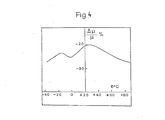
- FIG. 4 gives, as a function of the measurement temperature, the relative variation of the relative impedance permeability of the complete circuit measured at 50 Hz in a field of 8 mOe peak after an electric shock corresponding to 3 Oe.
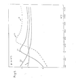
- FIG. 5 relates to a three-part circuit 11, 12 and 13 and gives, as a function of the measurement temperature, the relative permeability of impedance measured at 50 Hz in a field of 5m0e for the three constituent parts and for the complete circuit 1.
- the magnetic circuit according to the invention which is marked 1 as a whole in FIGS. 1 to 2 has a composite structure and consists of at least two parts 11 and 12.
- each of the parts is a torus formed by a continuous band wound in a spiral.
- the toroids can be nested one inside the other.
- each of the parts is a profile or a washer, these parts being stacked on top of each other.
- Each part is made of a magnetic alloy with very high permeability comprising more than 75% of nickel by weight and at least one element from the molybdenum, copper or chromium group.
- Each part of the composite circuit has a maximum relative permeability of impedance measured at 50 Hz at least equal to 200 x 10 3 G / Oe .
- the parts present different permeability curves of impedance as a function of the temperature which are different.
- the curve marked 11 corresponds to the permeability curve of the part or parts 11
- the curve marked 12 corresponds to the permeability curve of the part or parts designated 12.
- the curve designated 1 corresponds to the permeability curve of the entire composite circuit.
- the by tie 11 has a very high permeability at 20 ° C (300 x 10 3 G / Oe), and ine good stability after magnetization at 20 ° C
- Part 12 has very high permeabilities around -10 ° C (280 x 10 3 G / Oe) but relatively poor stability after magnetization at 20 ° C.
- the part 12 which has the greatest temperature stability around room temperature is preferably placed inside.
- the two tori 11 and 12 are separated by an annular space marked 14.
- this space is between 0.01 and 2 mm.
- some of the washers 11 or 12 may have a slit perpendicular to the mean direction of flow of the magnetic flux to increase the stability to electric shocks.
- This slot will be at least 0.01 mm and the proportion of split washers will be less than 50%. The proportion of split washers makes it possible to adapt the compromise between permeability and stability to electric shocks.
- the method according to the invention consists in developing the alloy chosen from one of the three families above.
- a conventional production method consists in preparing an ingot by casting. A thin strip of thickness typically less than 0.1 mm is then produced by hot and cold rolling.
- Annealing temperatures are between 800 and 1200 ° C and preferably between 1000 and 1200 ° C.
- the parts of the composite circuit then undergo a final annealing to adjust the permeability to around 500 ° C.
- the final annealing temperatures of the elements 11 and 12 are different and refer to the treatment temperature T a leading to the highest relative impedance permeability at room temperature. This curve is marked R in FIG. 5.
- the annealing temperature leading to the highest permeability at room temperature is approximately 495 ° C. for a Fe-Ni alloy with 80% nickel and 5 1 of molybdenum.
- a fraction of the parts of the circuit will be annealed at a temperature approximately 25 ° C below the treatment temperature T o .
- the part or parts thus treated will exhibit reduced variability in permeability as a function of temperature (curves 12).
- the other fraction of the circuit elements will be annealed at a temperature about 0 to 25 ° C higher than the temperature T o .
- the part or parts thus treated will have less thermal stability but good stability to electric shocks (curves 11).
- cooling elements between 50 and 300 ° C / h will be used ensuring temperature stability and cooling between 300 and 600 ° C / h for the other circuit element (s).
- Another method according to the invention consists in producing the constituent parts of the same circuit with different compositions with regard to at least one of the metals influencing the magnetic properties and belonging to the group nickel, molybdenum, chromium, copper.
- the differences in weight of the contents are from + or - 0.5 to 1% for each of these constituents.
- the compositions of the various elements of the circuit are chosen within the same family of alloys defined above.
- the parts made with different compositions undergo an identical heat treatment, which makes it possible to obtain, for one of the parts essentially, good permeability and great stability against electric shock and for the other part, high permeability and great stability with respect to -vis temperature variations on either side of the ambient temperature.
- the magnetic circuits according to the invention can be applied to differential transformers for circuit breakers or to specialized inductive components.
Landscapes
- Engineering & Computer Science (AREA)
- Power Engineering (AREA)
- Chemical & Material Sciences (AREA)
- Composite Materials (AREA)
- Physics & Mathematics (AREA)
- Electromagnetism (AREA)
- Dispersion Chemistry (AREA)
- Soft Magnetic Materials (AREA)
- Parts Printed On Printed Circuit Boards (AREA)
- Manufacturing Cores, Coils, And Magnets (AREA)
- Shielding Devices Or Components To Electric Or Magnetic Fields (AREA)
Abstract
Description
- La présente invention se rapporte d'une part à un circuit magnétique composite formé d'au moins deux parties en alliage magnétique doux et d'autre part à un procédé de fabrication dudit circuit.
- Certains circuits magnétiques, par exemple en forme d'anneaux circulaires ou de tores, que l'on utilise dans des appareillages électriques sont réalisés en alliage magnétique doux.
- Ces circuits ont parfois une structure composite obtenue par empilage de profils ou par association de deux tores souvent emboités l'un dans l'autre. On a par exemple réalisé des circuits composites dont une partie est en alliage à haute perméabilité initiale et dont l'autre est en alliage à haute induction à saturation. Ces circuits ne possèdent pas une perméabilité relative d'impédance suffisamment élevée pour certaines applications.
- Pour certains appareils de protection tels que des disjoncteurs différentiels ou des appareils similaires, on utilise des circuits magnétiques présentant une perméabilité relative d'impédance élevée. Néanmoins ces circuits ne présentent pas forcément une perméabilité relative d'impédance suffisamment stable au voisinage de la température de fonctionnement pour que les appareils de sécurité sur lesquels ils sont utilisés fonctionnent dans des conditions climatiques très différentes. D'autre part on n'obtient pas la garantie qu'après un choc électrique sur la ligne, qui en créant un champ magnétique sur le circuit l'aimante et le laisse ensuite dans un état magnétique mal défini, la perméabilité d'impédance du circuit magnétique reste peu différente de la perméabilité de ce même circuit dans l'état désaimanté.
- La présente invention a pour but de réaliser un circuit magnétique composite présentant une perméabilité élevée qui reste stable en fonction de la température dans une large plage autour de la température ambiante même après des chocs électriques.
- Le circuit magnétique composite selon l'invention est caractérisé par le fait que chacune des parties est constituée par un alliage nickel-fer à très haute perméabilité comportant plus de 75 % en poids de nickel et au moins un élément du groupe molybdène, cuivre, chrome et présentant une perméabilité relative maximale d'impédance mesurée à 50 Hz au moins égale à 200 x 103 G/Oe et que lesdites parties présentent des courbes différentes de perméabilité relative d'impédance en fonction de la température de mesure autour de. la température ambiante.
- Selon une caractéristique, l'une au moins des parties est en alliage contenant en poids 76 à 81 % de nickel, 4 à 6 % de molybdene, 0,2 à 0,7 % de manganèse et les impuretés classiques présentes dans ces alliages, le reste de fer.
- Selon une autre caractéristique, l'une au moins des parties est en alliage contenant en poids 75 à 80 de nickel, 4 à 6 % de cuivre, 3 à 5 % de molybdène, 0,2 à 0,7 5 de manganèse et les impuretés classiques présentes dans ces alliages, le reste de fer.
- Selon une autre caractéristique, l'une au moins des parties est en alliage contenant en poids 75 à 77 % de nickel, 4 à 6 5 de cuivre, 2 à 4 % de chrome, 0,2 à 0,7 % de manganèse et les impuretés classiques présentes dans ces alliages, le reste de fer.
- Le procédé de fabrication selon l'invention est caractérisé par le fait qu'il consiste à réaliser les parties du circuit en alliage comportant plus de 75 % en poids de nickel et au moins un élément du groupe molybdène-cuivre-chrome, à faire subir à au moins une desdistes parties un recuit d'ajustement de la perméabilité à une température inférieure de 5 à 35°C à la température optimale conduisant à la perméabilicé relative d'impédance la plus élevée à la température ambiante et à faire subir à au moins une desdites parties un recuit d'ajustement de la peréabilité à une température supérieure de 0 à 25°C à la température optimale conduisant à la perméabilité relative la plus élévée à la température ambiante.
- Selon une caractéristique du procédé, il consiste à réaliser les parties à partir de bandes minces obtenues par laminage à chaud et à froid puis à leur faire subir un recuit à plus de 800°C avant le recuit d'ajustement de la perméabilité.
- D'autres caractéristiques et avantages de l'invention ressortiront de la description suivante qui se réfère aux dessins annexés sur lesquels :
- La figure 1 représente un circuit composite selon l'invention du type à tores.
- La figure 2 représente un circuit composite selon l'invention du type à profils empilés.
- La figure 3 se rapporte à un circuit à deux patties pour lesquelles elle donne, en fonction de la température de mesure, la perméibilite relative d'impédance mesurée à 50 Hz dans un champ moyen de 5 millioersted- crête* pour les deux parties constitutives (Sigure la) et pour le circuit complet (figure 3b).
- * Note pour le traducteur : Average pic value of magnetie sield.
- La figure 4 donne, en fonction de la température de mesure, la variation relative de la perméabilité relative d'impédance du circuit complet mesurée à 50 Hz dans un champ de 8mOe crête après un choc électrique correspondant à 3 Oe.
- La figure 5 se rapporte à un circuit à trois parties 11, 12 et 13 et donne, en fonction de la température de mesure, la perméabilité relative d'impédance mesurée à 50 Hz dans un champ de 5m0e pour les trois parties constitutives et pour le circuit complet 1.
- Le circuit magnétique selon l'invention qui est repéré 1 dans son ensemble sur les figures 1 à 2 a une structure composite et se compose d'au moins deux parties 11 et 12. Dans le mode de réalisation de la figure 1, chacune des parties est un tore formé d'une bande continue enroulée en spirale. Dans ce cas, les tores peuvent être emboités l'un dans l'autre. Dans le mode de réalisation de la figure 2, chacune des parties est un profil ou une rondelle, ces parties étant empilées les unes sur les autres.
- Chaque partie est réalisée en un alliage magnétique à très haute perméabilité comportant plus de 75 % de nickel en poids et au moins un élément du groupe molybdène, cuivre ou chrome.
- A titre indicatif, l'alliage magnétique constituant les parties peut être choisi dans l'une des familles suivantes :
- Famille Ni - Fe - Mo : alliages contenant en poids 76 à 81 % de nickel, 4 à 6 X de molybdène, 0,2 à 0,7 % de manganèse et les impuretés classiques présentes dans ces alliages, le reste de fer.
- Famille Ni - Fe - Cu - Mo : alliages contenant en poids 75 à 80 % de nickel, 4 à 6 % de cuivre, 3 à 5 % de molybdène, 0,2 à 0,7 % de manganèse et les impuretés classiques présentes dans ces alliages, le reste de fer. Famille Ni - Fe - Cu - Cr : alliages contenant en poids 75 à 77 % de nickel, 4 à 6 % de cuivre, 2 à 4 % de chrome, 0,2 à 0,7 % de manganèse et les impuretés classiques présentes dans ces alliages, le reste de fer.
- Chaque partie du circuit composite présente une perméabilité relative maximale d'impédance mesurée à 50 Hz au moins égale à 200 x 103 G/Oe. Les parties présentent des courbes de perméabilité relative d'impédance en fonction de la température qui sont différentes. Ainsi, en se référant aux figures 3 et 4, la courbe repérée 11 correspond à la courbe de perméabilité de la ou des parties 11 et la courbe repérée 12 correspond à la courbe de perméabilité de la ou des parties désignées 12. La courbe désignée 1 correspond à la courbe de perméabilité de l'ensemble du circuit composite. La partie 11 présente une perméabilité très élevée à 20°C (300 x 103 G/Oe), et ine bonne stabilité après aimantation à 20°C La partie 12 présente des per- néabilités très élevées vers -10°C (280 x 103 G/Oe) mais une stabilité après aimantation à20°C relativement médiocre.
- Dans le mode de réalisation de la figure 1, la partie 12 qui présente la plus grande stabilité en température autour de la température ambiante est de préférence placé à l'intérieur. Les deux tores 11 et 12 sont séparés par un espace annulaire repéré 14. De préférence cet espace est compris entre 0,01 et 2 mm.
- Dans le mode de réalisation de la figure 2, certaines des rondelles 11 ou 12 peuvent présenter une fente perpendiculaire au sens d'écoulement moyen du flux magnétique pour accroître la stabilité aux chocs électriques. Cette fente aura au minimum 0,01 mm et la proportion de rondelles fendues sera inférieure à 50 %. La proportion des rondelles fendues permet d'adapter le compromis entre la perméabilité et la stabilité aux chocs électriques.
- Le procédé selon l'invention consiste à élaborer l'alliage choisi dans l'une des trois familles ci-dessus.
- Une méthode d'élaboration classique consiste à préparer un lingot par coulée. On réalise ensuite par laminage à chaud et à froid une bande mince d'épaisseur typiquement inférieure à 0,1 mm.
- Ces bandes servent à fabriquer des tores ou des profils ou des rondelles.
- Les parties subissent ensuite un recuit. Les températures de recuit se situent entre 800 et 1200°C et de préférence entre 1000 et 1200°C.
- Les parties du circuit composite subissent ensuite un recuit final d'ajustement de la perméabilité vers 500°C. Dans un premier mcde de réalisation du procédé, les tempéra tures de recuit final des éléments 11 et 12 sont différentes et se réfèrent à la température de traitement Ta conduisant à la perméabilité relative d'impédance la plus élevée à la température ambiante. Cette courbe est repérée R sur la figure 5. A titre indicatif, la température de recuit conduisant à la perméabilité la plus élevée à la température ambiante est de 495°C environ pour un alliage Fe-Ni à 80 % de nickel et 5 1 de molybdène. Une fraction des parties du circuit subira un recuit à une température inférieure d'environ à 25°C à la température de traitement To. La ou les parties ainsi traitées présenteront une variabilité réduite de la perméabilité en fonction de la température (courbes 12).
- L'autre fraction des éléments du circuit subira un recuit à une température supérieure d'environ 0 à 25°C à la température To. La ou les parties ainsi traitées présenteront une stabilité thermique moindre mais une bonne stabilité aux chocs électriques (courbes 11).
- Il est possible d'associer plus de deux parties dans un même circuit magnétique afin d'affiner soit la stabilité en température soit la stabilité aux chocs électriques. La figure 5 illustre cette possibilité.
- En variante du procédé précédent, on pourra pour ajuster les propriétés magnétiques des parties du circuit, effectuer des refroidissements après recuit final à des vitesses différentes pour les différentes parties du même circuit ou encore effectuer des recuits étagés différents pour les différentes parties du circuit.
- Ainsi à titre indicatif, si on obtient la plus grande perméabilité à l'ambiante à la suite d'un refroidissement à 300°C/h après recuit à 700°C on utilisera des refroidissements entre 50 et 300°C/h pour les éléments assurant la stabilité en température et des refroidissements entre 300 et 600°C/h pour le ou les autres éléments du circuit.
- Un autre procédé selon l'invention consiste à réaliser les parties constitutives d'un même circuit avec des compositions différentes pour ce qui concerne au moins un des métaux influant sur les propriétés magnétiques et appartenant au groupe nickel, molybdène, chrome, cuivre. De préférence, les différences en poids des teneurs sont de + ou - 0,5 à 1 % pour chacun de ces constituants. De préférence, les compositions des divers éléments du circuit sont choisies à l'intérieur d'une même famille d'alliages définie ci-dessus.
- Les parties réalisées avec des compositions différentes subissent un traitement thermique identique, ce qui permet d'obtenir pour une des parties essentiellement une bonne perméabilité et une grande stabilité aux chocs électriques et pour l'autre partie une perméabilité élevée et une grande stabilité vis-à-vis des variations de température de part et d'autre de la température ambiante.
- Il est préférable après avoir réalisé les alliages de composi- tions différentes de déterminer leur température To à laquelle ils présentent la perméabilité la plus élévée à la température ambiante et ensuite de les associer de façon à réaliser le plus avantageusement possible au cours d'un seul traitement les propriétés magnétiques recherchées.
- Les circuits magnétiques selon l'invention peuvent être appliqués à des transformateurs différentiels pour disjoncteurs ou à des composants inductifs spécialisés.
- Il est bien évident que l'on peut, sans sortir du cadre de l'invention, imaginer des variantes et perfectionnements de détails, et de même envisager l'emploi de moyens équivalents.
- Il est possible de jouer sur les sections des différentes parties d'un même circuit composite pour adapter le circuit à l'utilisation désirée.
Claims (14)
Priority Applications (1)
| Application Number | Priority Date | Filing Date | Title |
|---|---|---|---|
| AT85400402T ATE29331T1 (de) | 1984-03-02 | 1985-03-01 | Zusammengesetzter, magnetischer kreis und verfahren zur herstellung dieses kreises. |
Applications Claiming Priority (2)
| Application Number | Priority Date | Filing Date | Title |
|---|---|---|---|
| FR8403266 | 1984-03-02 | ||
| FR8403266A FR2560711B1 (fr) | 1984-03-02 | 1984-03-02 | Circuit magnetique composite et procede de fabrication dudit circuit |
Publications (2)
| Publication Number | Publication Date |
|---|---|
| EP0157669A1 true EP0157669A1 (fr) | 1985-10-09 |
| EP0157669B1 EP0157669B1 (fr) | 1987-09-02 |
Family
ID=9301621
Family Applications (1)
| Application Number | Title | Priority Date | Filing Date |
|---|---|---|---|
| EP85400402A Expired EP0157669B1 (fr) | 1984-03-02 | 1985-03-01 | Circuit magnétique composite et procédé de fabrication dudit circuit |
Country Status (6)
| Country | Link |
|---|---|
| EP (1) | EP0157669B1 (fr) |
| AT (1) | ATE29331T1 (fr) |
| DE (1) | DE3560540D1 (fr) |
| ES (1) | ES8700791A1 (fr) |
| FR (1) | FR2560711B1 (fr) |
| ZA (1) | ZA851595B (fr) |
Cited By (4)
| Publication number | Priority date | Publication date | Assignee | Title |
|---|---|---|---|---|
| FR2631350A1 (fr) * | 1988-05-13 | 1989-11-17 | Nippon Kokan Kk | Alliage de ni-fe ferromagnetique et procede de fabrication de brames ayant une qualite de surface excellente en cet alliage |
| US6580348B1 (en) | 1999-02-22 | 2003-06-17 | Vacuumschmelze Gmbh | Flat magnetic core |
| EP1655745A1 (fr) * | 2004-11-09 | 2006-05-10 | ABB Oy | Inductance |
| KR100913878B1 (ko) * | 1999-08-09 | 2009-08-26 | 바이엘 크롭사이언스 아게 | 발아후 살포용 제초제를 포함하는 토양 살포용 제초 제제 |
Citations (6)
| Publication number | Priority date | Publication date | Assignee | Title |
|---|---|---|---|---|
| CH119056A (fr) * | 1924-11-25 | 1927-03-01 | Bell Telephone Mfg | Corps magnétique et procédé de fabrication de ce corps. |
| US1880805A (en) * | 1932-03-16 | 1932-10-04 | Bell Telephone Labor Inc | Inductive device |
| DE937185C (de) * | 1941-02-12 | 1955-12-29 | Siemens Ag | Schaltanordnung fuer Wechselstromunterbrechungseinrichtungen |
| US4205288A (en) * | 1978-10-27 | 1980-05-27 | Westinghouse Electric Corp. | Transformer with parallel magnetic circuits of unequal mean lengths and loss characteristics |
| DE3026498A1 (de) * | 1980-07-12 | 1982-02-04 | Fried. Krupp Gmbh, 4300 Essen | Verfahren zur herstellung von ringbandkernen |
| DE3107754A1 (de) * | 1981-02-28 | 1982-09-16 | Vacuumschmelze Gmbh, 6450 Hanau | Verfahren zum herstellen von ringbandkernen fuer fehlerstromschutzschalter und verwendung dieser kerne |
Family Cites Families (1)
| Publication number | Priority date | Publication date | Assignee | Title |
|---|---|---|---|---|
| JPS5612705A (en) * | 1979-07-13 | 1981-02-07 | Toshiba Corp | Raw material for magnetic head core |
-
1984
- 1984-03-02 FR FR8403266A patent/FR2560711B1/fr not_active Expired
-
1985
- 1985-03-01 ZA ZA851595A patent/ZA851595B/xx unknown
- 1985-03-01 AT AT85400402T patent/ATE29331T1/de not_active IP Right Cessation
- 1985-03-01 ES ES540840A patent/ES8700791A1/es not_active Expired
- 1985-03-01 EP EP85400402A patent/EP0157669B1/fr not_active Expired
- 1985-03-01 DE DE8585400402T patent/DE3560540D1/de not_active Expired
Patent Citations (6)
| Publication number | Priority date | Publication date | Assignee | Title |
|---|---|---|---|---|
| CH119056A (fr) * | 1924-11-25 | 1927-03-01 | Bell Telephone Mfg | Corps magnétique et procédé de fabrication de ce corps. |
| US1880805A (en) * | 1932-03-16 | 1932-10-04 | Bell Telephone Labor Inc | Inductive device |
| DE937185C (de) * | 1941-02-12 | 1955-12-29 | Siemens Ag | Schaltanordnung fuer Wechselstromunterbrechungseinrichtungen |
| US4205288A (en) * | 1978-10-27 | 1980-05-27 | Westinghouse Electric Corp. | Transformer with parallel magnetic circuits of unequal mean lengths and loss characteristics |
| DE3026498A1 (de) * | 1980-07-12 | 1982-02-04 | Fried. Krupp Gmbh, 4300 Essen | Verfahren zur herstellung von ringbandkernen |
| DE3107754A1 (de) * | 1981-02-28 | 1982-09-16 | Vacuumschmelze Gmbh, 6450 Hanau | Verfahren zum herstellen von ringbandkernen fuer fehlerstromschutzschalter und verwendung dieser kerne |
Non-Patent Citations (8)
| Title |
|---|
| ANNALES FRANCAISES DE CHRONOMETRIE ET DE MICRO-MECANIQUE, 1971, pages 49-53; E. JOSSO: "Les alliages magnétiques doux au service de la chronométrie" * |
| IEEE TRANSACTIONS ON MAGNETICS, vol. MAG-10, no. 2, juin 1974, pages 139 et 140; ZDENEK SVESTKA et al.: "The effect of manganese on the magnetic propperties of mumetal alloy", * |
| IEEE TRANSACTIONS ON MAGNETICS, volume MAG-12, no. 6, novembre 1976, pages 801-803; K. YAMASAWA et al.:"Thermomagnetic characteristics of cores composed of teperature-sensitive magnetic materials" * |
| L'ONDE ELECTRIQUE, volume 42, février 1962, pages 91-117; A. DANZIN et al.: "Electronique et métallurgie. Les apports de la métallurgie à l'électronique" * |
| PATENTS ABSTRACTS OF JAPAN, volume 5, no. 63, 735 e-54, 28 avril 1981, & JP - A - 56 12 705 (TOKYO SHIBAURA DENKI) 07-02-1981 * |
| TECHNISCHE MITTEILUNGEN KRUPP FORSCHUNGSBERICHTE, volume 40, no. 3, novembre 1982, pages 61-66, Essen, DE; W. WOLF: "Hochpermeable metallische Magnetkerne für elektrotechnische Bauteile" * |
| TECHNISCHE MITTEILUNGEN KRUPP, vol. 38, no. 2, août 1980, pages 9 5-102, Essen, DE; W. WOLF: "Neue weichmagnetische Nickeleisen-Werkstoffe" * |
| ZEITSCHRIFT FÜR ANGEWANDTE PHYSIK, volume 13, no. 4, 1961, pages 177-180; F. PFEIFER: "Permalloylegierungen mit Rechteckschleife" * |
Cited By (4)
| Publication number | Priority date | Publication date | Assignee | Title |
|---|---|---|---|---|
| FR2631350A1 (fr) * | 1988-05-13 | 1989-11-17 | Nippon Kokan Kk | Alliage de ni-fe ferromagnetique et procede de fabrication de brames ayant une qualite de surface excellente en cet alliage |
| US6580348B1 (en) | 1999-02-22 | 2003-06-17 | Vacuumschmelze Gmbh | Flat magnetic core |
| KR100913878B1 (ko) * | 1999-08-09 | 2009-08-26 | 바이엘 크롭사이언스 아게 | 발아후 살포용 제초제를 포함하는 토양 살포용 제초 제제 |
| EP1655745A1 (fr) * | 2004-11-09 | 2006-05-10 | ABB Oy | Inductance |
Also Published As
| Publication number | Publication date |
|---|---|
| ZA851595B (en) | 1985-10-30 |
| DE3560540D1 (en) | 1987-10-08 |
| FR2560711B1 (fr) | 1987-03-20 |
| FR2560711A1 (fr) | 1985-09-06 |
| ES8700791A1 (es) | 1986-10-16 |
| ES540840A0 (es) | 1986-10-16 |
| ATE29331T1 (de) | 1987-09-15 |
| EP0157669B1 (fr) | 1987-09-02 |
Similar Documents
| Publication | Publication Date | Title |
|---|---|---|
| EP3329027B1 (fr) | Tôle ou bande en alliage feco ou fesi ou en fe et son procédé de fabrication, noyau magnétique de transformateur réalisé à partir d'elle et transformateur le comportant | |
| US4364020A (en) | Amorphous metal core laminations | |
| EP0848397B1 (fr) | Procédé de fabrication d'un composant magnétique en alliage magnétique doux à base de fer ayant une structure nanocristalline | |
| JP2607023B2 (ja) | 磁性デバイスの作製方法 | |
| EP0792943B1 (fr) | Alliage fer-nickel et bande laminée à froid à texture cubique | |
| CA3038893C (fr) | Noyau de transformateur du type decoupe-empile, et transformateur le comportant | |
| CA1100585A (fr) | Transformateur polyphase de resistance mecanique elevee | |
| EP0157669B1 (fr) | Circuit magnétique composite et procédé de fabrication dudit circuit | |
| JPS6169103A (ja) | 高周波高透磁率磁性材料 | |
| EP0784100A1 (fr) | Alliage fer-cobalt, procédé de fabrication d'une bande en alliage fercobalt et bande obtenue | |
| JP3634286B2 (ja) | Fe基非晶質合金薄帯とそれを用いて製造した鉄心 | |
| CA1211169A (fr) | Transformateur de distribution a circuit magnetique enroule | |
| JP7271064B2 (ja) | 積層鉄心用板材の製造方法、積層鉄心用板材および積層鉄心 | |
| US3903586A (en) | Method of making laminated magnetic material | |
| NL8100505A (nl) | Magnetische legering. | |
| EP0786528A1 (fr) | Procédé de fabrication de tÔle d'acier magnétique à grains non orientés et tÔle obtenue par le procédé | |
| US5456770A (en) | Amorphous magnetic alloy with high magnetic flux density | |
| JPH0697646B2 (ja) | 非晶質磁性合金巻鉄心 | |
| FR2652944A1 (fr) | Structure composite resistant aux chocs thermiques et application aux condensateurs ceramiques multicouches. | |
| JPS59177349A (ja) | 低鉄損一方向性珪素鋼板 | |
| US4682486A (en) | Amorphous alloy toroids | |
| KR900010029A (ko) | 구리기초형상기억 합금 및 그 제조방법 | |
| SU33051A1 (ru) | Способ изготовлени железо-кобальт-никелевых сплавов, обладающих высоким посто нством магнитной проницаемости и большом диапазоне напр жени магнитного пол | |
| FR2491499A1 (fr) | Alliage magnetique anisotrope et procede de fabrication | |
| JPH0449723B2 (fr) |
Legal Events
| Date | Code | Title | Description |
|---|---|---|---|
| PUAI | Public reference made under article 153(3) epc to a published international application that has entered the european phase |
Free format text: ORIGINAL CODE: 0009012 |
|
| AK | Designated contracting states |
Designated state(s): AT BE CH DE GB IT LI LU NL SE |
|
| 17P | Request for examination filed |
Effective date: 19851115 |
|
| 17Q | First examination report despatched |
Effective date: 19861023 |
|
| GRAA | (expected) grant |
Free format text: ORIGINAL CODE: 0009210 |
|
| AK | Designated contracting states |
Kind code of ref document: B1 Designated state(s): AT BE CH DE GB IT LI LU NL SE |
|
| REF | Corresponds to: |
Ref document number: 29331 Country of ref document: AT Date of ref document: 19870915 Kind code of ref document: T |
|
| REF | Corresponds to: |
Ref document number: 3560540 Country of ref document: DE Date of ref document: 19871008 |
|
| GBT | Gb: translation of ep patent filed (gb section 77(6)(a)/1977) | ||
| ITF | It: translation for a ep patent filed | ||
| PLBE | No opposition filed within time limit |
Free format text: ORIGINAL CODE: 0009261 |
|
| STAA | Information on the status of an ep patent application or granted ep patent |
Free format text: STATUS: NO OPPOSITION FILED WITHIN TIME LIMIT |
|
| 26N | No opposition filed | ||
| PGFP | Annual fee paid to national office [announced via postgrant information from national office to epo] |
Ref country code: GB Payment date: 19930301 Year of fee payment: 9 |
|
| PGFP | Annual fee paid to national office [announced via postgrant information from national office to epo] |
Ref country code: LU Payment date: 19930303 Year of fee payment: 9 |
|
| PGFP | Annual fee paid to national office [announced via postgrant information from national office to epo] |
Ref country code: AT Payment date: 19930305 Year of fee payment: 9 |
|
| PGFP | Annual fee paid to national office [announced via postgrant information from national office to epo] |
Ref country code: BE Payment date: 19930316 Year of fee payment: 9 |
|
| PGFP | Annual fee paid to national office [announced via postgrant information from national office to epo] |
Ref country code: SE Payment date: 19930322 Year of fee payment: 9 |
|
| PGFP | Annual fee paid to national office [announced via postgrant information from national office to epo] |
Ref country code: CH Payment date: 19930329 Year of fee payment: 9 |
|
| ITTA | It: last paid annual fee | ||
| PGFP | Annual fee paid to national office [announced via postgrant information from national office to epo] |
Ref country code: NL Payment date: 19930331 Year of fee payment: 9 |
|
| PGFP | Annual fee paid to national office [announced via postgrant information from national office to epo] |
Ref country code: DE Payment date: 19930423 Year of fee payment: 9 |
|
| EPTA | Lu: last paid annual fee | ||
| PG25 | Lapsed in a contracting state [announced via postgrant information from national office to epo] |
Ref country code: LU Free format text: LAPSE BECAUSE OF NON-PAYMENT OF DUE FEES Effective date: 19940301 Ref country code: GB Effective date: 19940301 Ref country code: AT Effective date: 19940301 |
|
| PG25 | Lapsed in a contracting state [announced via postgrant information from national office to epo] |
Ref country code: SE Free format text: LAPSE BECAUSE OF NON-PAYMENT OF DUE FEES Effective date: 19940302 |
|
| PG25 | Lapsed in a contracting state [announced via postgrant information from national office to epo] |
Ref country code: LI Effective date: 19940331 Ref country code: CH Effective date: 19940331 Ref country code: BE Effective date: 19940331 |
|
| BERE | Be: lapsed |
Owner name: IMPHY S.A. Effective date: 19940331 |
|
| PG25 | Lapsed in a contracting state [announced via postgrant information from national office to epo] |
Ref country code: NL Effective date: 19941001 |
|
| GBPC | Gb: european patent ceased through non-payment of renewal fee |
Effective date: 19940301 |
|
| NLV4 | Nl: lapsed or anulled due to non-payment of the annual fee | ||
| REG | Reference to a national code |
Ref country code: CH Ref legal event code: PL |
|
| PG25 | Lapsed in a contracting state [announced via postgrant information from national office to epo] |
Ref country code: DE Effective date: 19941201 |
|
| EUG | Se: european patent has lapsed |
Ref document number: 85400402.5 Effective date: 19941010 |