EP0157894B2 - Verfahren und Vorrichtung zur Erhöhung der Wandstärke von Rohren - Google Patents
Verfahren und Vorrichtung zur Erhöhung der Wandstärke von Rohren Download PDFInfo
- Publication number
- EP0157894B2 EP0157894B2 EP84104086A EP84104086A EP0157894B2 EP 0157894 B2 EP0157894 B2 EP 0157894B2 EP 84104086 A EP84104086 A EP 84104086A EP 84104086 A EP84104086 A EP 84104086A EP 0157894 B2 EP0157894 B2 EP 0157894B2
- Authority
- EP
- European Patent Office
- Prior art keywords
- tubular member
- thickness
- heating
- frequency
- heater
- Prior art date
- Legal status (The legal status is an assumption and is not a legal conclusion. Google has not performed a legal analysis and makes no representation as to the accuracy of the status listed.)
- Expired
Links
Images


Classifications
-
- B—PERFORMING OPERATIONS; TRANSPORTING
- B60—VEHICLES IN GENERAL
- B60G—VEHICLE SUSPENSION ARRANGEMENTS
- B60G21/00—Interconnection systems for two or more resiliently-suspended wheels, e.g. for stabilising a vehicle body with respect to acceleration, deceleration or centrifugal forces
- B60G21/02—Interconnection systems for two or more resiliently-suspended wheels, e.g. for stabilising a vehicle body with respect to acceleration, deceleration or centrifugal forces permanently interconnected
- B60G21/04—Interconnection systems for two or more resiliently-suspended wheels, e.g. for stabilising a vehicle body with respect to acceleration, deceleration or centrifugal forces permanently interconnected mechanically
- B60G21/05—Interconnection systems for two or more resiliently-suspended wheels, e.g. for stabilising a vehicle body with respect to acceleration, deceleration or centrifugal forces permanently interconnected mechanically between wheels on the same axle but on different sides of the vehicle, i.e. the left and right wheel suspensions being interconnected
- B60G21/055—Stabiliser bars
- B60G21/0551—Mounting means therefor
-
- B—PERFORMING OPERATIONS; TRANSPORTING
- B21—MECHANICAL METAL-WORKING WITHOUT ESSENTIALLY REMOVING MATERIAL; PUNCHING METAL
- B21C—MANUFACTURE OF METAL SHEETS, WIRE, RODS, TUBES, PROFILES OR LIKE SEMI-MANUFACTURED PRODUCTS OTHERWISE THAN BY ROLLING; AUXILIARY OPERATIONS USED IN CONNECTION WITH METAL-WORKING WITHOUT ESSENTIALLY REMOVING MATERIAL
- B21C37/00—Manufacture of metal sheets, rods, wire, tubes, profiles or like semi-manufactured products, not otherwise provided for; Manufacture of tubes of special shape
- B21C37/06—Manufacture of metal sheets, rods, wire, tubes, profiles or like semi-manufactured products, not otherwise provided for; Manufacture of tubes of special shape of tubes or metal hoses; Combined procedures for making tubes, e.g. for making multi-wall tubes
- B21C37/15—Making tubes of special shape; Making tube fittings
- B21C37/16—Making tubes with varying diameter in longitudinal direction
-
- B—PERFORMING OPERATIONS; TRANSPORTING
- B21—MECHANICAL METAL-WORKING WITHOUT ESSENTIALLY REMOVING MATERIAL; PUNCHING METAL
- B21J—FORGING; HAMMERING; PRESSING METAL; RIVETING; FORGE FURNACES
- B21J5/00—Methods for forging, hammering, or pressing; Special equipment or accessories therefor
- B21J5/06—Methods for forging, hammering, or pressing; Special equipment or accessories therefor for performing particular operations
- B21J5/08—Upsetting
-
- B—PERFORMING OPERATIONS; TRANSPORTING
- B21—MECHANICAL METAL-WORKING WITHOUT ESSENTIALLY REMOVING MATERIAL; PUNCHING METAL
- B21J—FORGING; HAMMERING; PRESSING METAL; RIVETING; FORGE FURNACES
- B21J9/00—Forging presses
- B21J9/02—Special design or construction
- B21J9/06—Swaging presses; Upsetting presses
- B21J9/08—Swaging presses; Upsetting presses equipped with devices for heating the work-piece
-
- B—PERFORMING OPERATIONS; TRANSPORTING
- B60—VEHICLES IN GENERAL
- B60G—VEHICLE SUSPENSION ARRANGEMENTS
- B60G2204/00—Indexing codes related to suspensions per se or to auxiliary parts
- B60G2204/10—Mounting of suspension elements
- B60G2204/12—Mounting of springs or dampers
- B60G2204/122—Mounting of torsion springs
- B60G2204/1222—Middle mounts of stabiliser on vehicle body or chassis
-
- B—PERFORMING OPERATIONS; TRANSPORTING
- B60—VEHICLES IN GENERAL
- B60G—VEHICLE SUSPENSION ARRANGEMENTS
- B60G2204/00—Indexing codes related to suspensions per se or to auxiliary parts
- B60G2204/40—Auxiliary suspension parts; Adjustment of suspensions
- B60G2204/44—Centering or positioning means
-
- B—PERFORMING OPERATIONS; TRANSPORTING
- B60—VEHICLES IN GENERAL
- B60G—VEHICLE SUSPENSION ARRANGEMENTS
- B60G2204/00—Indexing codes related to suspensions per se or to auxiliary parts
- B60G2204/40—Auxiliary suspension parts; Adjustment of suspensions
- B60G2204/45—Stops limiting travel
-
- B—PERFORMING OPERATIONS; TRANSPORTING
- B60—VEHICLES IN GENERAL
- B60G—VEHICLE SUSPENSION ARRANGEMENTS
- B60G2206/00—Indexing codes related to the manufacturing of suspensions: constructional features, the materials used, procedures or tools
- B60G2206/01—Constructional features of suspension elements, e.g. arms, dampers, springs
- B60G2206/40—Constructional features of dampers and/or springs
- B60G2206/42—Springs
- B60G2206/427—Stabiliser bars or tubes
Definitions
- This invention relates to a method for increasing the thickness of a tubular member of the kind referred to in the pre-characterizing portion of claim 1 Such a method known from DE-C-1 002 594.
- a conventional method of increasing the thickness of a tubular member performs an upsetting process by applying a compressive force to the tubular member in its axial direction so as to increase the thickness of the tubular member.
- this conventional method which effects upsetting by applying a compressive force that is, a simple compressive process method
- a simple compressive process method can not accomplish a uniform increase in thickness, but produces irregular deformation of the tubular method such as wrinkles and buckling.
- a simple compressive process method When the thickness of a pipe is increased by a simple compressive process, deformation takes place throughout the entire length of the pipe, so that irregular deformations such as wrinkles and buckling are likely to occur, as described above.
- the thickness increase occurs on both the outer and inner diameter sides of the pipe.
- the increase in thickness on the inner diameter side increases the proportion of the fall of flow rate of a fluid flowing therethrough, causing problems such that cavitation occurs at that portion and corrosion develops thereat while the pipe is in use.
- Prior art document DE-C-1 002 594 proposes a method of increasing the thickness of a tubular member in which the tubular member is set into a supporter, the tubular member is then heated and a compressive force is applied in the axial direction of the tubular member. Further rollers or dies are applied to the inner and outer surfaces of the tubular member to limit the extension of the growth in thickness of the tubular member and to prevent irregularities of the surfaces of said tubular member.
- the present invention is directed to an improvement of a method of increasing the thickness of a tubular member of the kind mentioned above in that no further measures and means as such needed for compressing are necessary to provide a uniform thickness increase without causing any irregular deformations such as wrinkles and buckling, and which can reduce the thickness increase on the inner diameter side.
- the apparatus includes loading means capable of compressing the tubular member in the axial direction, an annular heating coil positioned around the outer circumference of the tubular member and which is capable of moving in the axial direction of the tubular member, a high-frequency oscillator generating a high-frequency current applied to the heating coil, and a frequency controller capable of controlling the frequency of the high-frequency current.
- the apparatus has the following construction.
- the compressive force is applied to the tubular member while it is being heated locally by a combination of high frequency induction heating and forced cooling, so as to limit the deformation region.
- the depth of penetration of the current varies according to the frequency of the high-frequency current. If the penetration depth is small, a temperature gradient is produced in the thickness direction of the workpiece being heated, so that deformation resistance is small on the high-temperature side (surface layer portion) of the workpiece, but high on the low-temperature side, so that a deformation resistance gradient is produced in the thickness direction.
- the frequency of the high-frequency current used in the high-frequency induction heating is set in such a manner that a desired temperature gradient is obtained in the thickness direction.
- the ratio of the increase in thickness on the outer diameter side to the increase in thickness on the inner diameter side can be controlled, and the increase of thickness on the inner diameter side can be reduced.
- Figure 1 is a partially sectioned view of an example of the apparatus for increasing the thickness of a tubular member together with a tubular member being subjected to the process.
- reference numeral 1 represents the tubular member which is the workpiece
- 2 is a press bed equipped with a seHing portion 2a for setting one of the ends of the tubular member
- 3 is a plate equipped on one side surface (on the left in Figure 1) with an hydraulic stepping cylinder 4
- 5a and 5b are support rods positioned opposite to each other with a predetermined spacing between them, which are able to subject the reaction of a compressive force.
- the support rod 5b also acts as a guide for a transformer 6 as it moves in the axial direction.
- Reference numeral 7 represents an annular heating coil which is arranged around the outer circumference of the tubular member 1 and can heat it. This heating coil 7 can move together with the transformer 6 in the axial direction of the tubular member 1. Orifices 7a are provided around the inner peripheral surface of the coil 7 on the opposite side to the direction of advance of the coil, represented by arrow A, these spray part of cooling water 8 for cooling the heating coil 7 onto the tubular member at an angle of about 45°.
- a non-contact type of thermometer 9 which can detect the temperature of the heated portion of the tubular member 1 is integrally mounted on the heating coil 7. The thermometer 9 is connected to a control unit 10 by lead wires 9a so that a signal is generated when the heated portion reaches a predetermined temperature.
- Reference numeral 11 represents a cooling water pipe for supplying the cooling water to the heating coil 7 in the direction represented by arrows B.
- Reference numeral 12 represents a high-frequency oscillator that generates a high-frequency current
- reference numeral 13 represents a frequency controller which controls a voltage by signals from the control unit 10 and the frequency of the high-frequency current, and is provided with a frequency-setting dial 13a.
- the transformer 6 controls the magnitude of the high-frequency current supplied to the coil 7, and is provided with a driving portion which is equipped with a relay switch which is turned on by a signal from the control unit 10, and is turned off by a signal from a limit switch 14, and with a heating coil speed-setting dial 6a.
- the transformer 6 moves in the direction represented by arrow C in the axial direction of the tubular member 1, guided by the support rod 5a, and thus can move the heating coil 7 at the predetermined speed.
- Reference numeral 4 represents a hydraulic cylinder associated with the loading means.
- the hydraulic stepping cylinder 4 includes a relay switch which is turned on by a signal from the control unit 10, and is turned off by a signal from the limit switch 14, and a hydraulic pressure-setting dial 4a.
- Reference numeral 15 represents a hydraulic device supplying a predetermined quantity of oil from hydraulic piping 16a to the hydraulic stepping cylinder 4, and reference numeral 16b represents hydraulic piping for returning the oil.
- Reference number 17 represents a spindle of the hydraulic stepping cylinder 4 which applies pressure to the tubular member 1 via a support jig 18 disposed at the end thereof, in the direction represented by arrow D.
- the limit switch 14 generates a signal when the heating coil 7 has finished heating up to the end of the increased thickness portion and the transformer has come into contact with the limit switch 14.
- the signal from the limit switch 14 is sent to the relay switch of the transformer 6, to the high-frequency oscillator 12, and to the relay switch of the hydraulic stepping cylinder 4, so that the transformer 6 stops, the driving of the hydraulic stepping cylinder 4 stops, and the high-frequency oscillator 12 stops generating the high-frequency current.
- the spindle 17 of the hydraulic stepping cylinder 4 and the transformer 6 are first moved back.
- the tubular member 1 which is the workpiece is then inserted into the heating coil 7, and one of its ends is then inserted into the setting portion 2a of the press head 2, and the other end is held in the supportjig 18 by the spindle 17 advancing in the direction indicated by arrow D.
- the transformer 6 is moved forward until the heating coil 7 reaches one end of the portion of the tubular member 1 whose thickness is to be increased.
- thermometer 9 of the heating coil 7 is then set to a predetermined temperature, and the frequency of the high-frequency current is likewise set by the frequency-setting dial 13a of the frequency controller 13.
- the speed of the heating coil and transformer 6 are set by the heating coil speed-setting dial 6a of the transformer 6, while the pressure of the hydraulic cylinder is set by the pressure-setting dial 4a of the hydraulic stepping cylinder 4.
- the high-frequency oscillator 12 is turned on so that the heating coil 7 starts the high-frequency induction heating of the tubular member 1, and at the same time the cooling water 8 is supplied from the cooling water pipe 11 to the heating coil 7.
- the control unit 10 of the non-contact type of thermometer 9 When the portion of the tubular member 1 heated by the heating coil 7 reaches the predetermined temperature described above, the control unit 10 of the non-contact type of thermometer 9 generates a signal which is thereafter received by the relay switoh of the hydraulic stepping cylinder 4 and by the relay switch of the driving portion of the transformer 6. Then the hydraulic stepping cylinder 4 is turned on and pushes the spindle 17 forward by the oil supplied from the hydraulic device 15 at the predetermined pressure, so that the tubular member 1 is compressed in the axial direction, that is, in the direction indicated by arrow D, with a predetermined compressive force.
- the relay switch of the transformer 6 is also turned on, and the transformer moves in the direction indicated by arrow D at the preset transformer speed, so that the heating of the tubular member is continued at the predetermined temperature.
- the quantity of water sprayed from the orifices 7a of the heating coil 7 is adjusted so that the width of the heating is at most about twice the thickness of the workpiece, and the deformation range of the tubular member is thus reduced.
- the temperature of the tubular member 1 is sensed by the non-contact type of thermometer 9, and is controlled since the voltage of the oscillator 12 for the high-frequency current is controlled on the basis of signals from the control unit 10.
- the transformer 6 When the transformer has moved forward in the direction indicated by arrow C so that the heating coil 7 has finished heating the other end of the portion of the tubular member 1 whose thickness is being increased, the transformer 6 comes into contact with the limit switch 14, whereupon movement of the transformer 6 as well as the driving of the hydraulic stepping cylinder4 stop, and the high-frequency oscillator 12 stops generating the high-frequency current.
- the conditions of the high-frequency induction heating by the heating coil 7 were as follows. The frequency was 9 kHz, the output was 85 kW, the heating temperature was 850°C, the speed of the heating coil 7 was 1 mm/min, and the set pressure of the hydraulic stepping cylinder 4 was 53.8 kg/cm 2 .
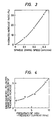
- Figure 3 is a graph of the relationship between the driving speed of the spindle and the thickness increase ratio.
- the curve in Figure 3 represents the relationship between the driving speed of the spindle 17 and the thickness increase ratio when the speed of the heating coil 7 is 1 mm/min.
- the driving speed of the spindle 17 should be set to about 0.3 mm/min in order to obtain a thickness increase ratio of 31 %.
- Figure 4 is a graph of the relationship between the frequency of the high-frequency current for the high-frequency induction heating and an innerdiameter-to-outer diameter distribution of the thickness increase, for a constant the speed of the heating coil.
- the curve in Figure 4 represents the relationship between the frequency of the high-frequency current and the inner diameter-to-outer diameter distribution of the thickness increase when the speed of the heating coil 7 is 1 mm/min.
- the inner diameter-to-outer diameter distribution of the thickness increase may be approximately 5 if the thickness increase on the inner diameter side is within the range of tolerances of thickness stipulated by JIS (Japanese Industrial Standards).
- the frequency corresponding to this inner diameter-to-outer diameter distribution of the thickness increase of 5 is 9 KHz. Hence, the frequency was set to 9 KHz.
- Figure 5 is a perspective view of an example of a tubular member which has been subjected to an increase in thickness by the apparatus for increasing thickness of Figure 1.
- Figure 6 is an enlarged section of part of the tubular member of Figure 5 including the portion whose thickness has been increased.
- reference numeral 20 represents the thickened portion of the tubular member 1
- 20a is the thickened portion on the outer diameter side
- 20b is the thickened portion on the inner diameter side.
- the thickness increase ratio (31 %) of the thickened portion 20 is uniform and is completely devoid of any irregular deformation. In addition, the thickness increase on the inner diameter side is small. (The inner diameter-to-outer diameter distribution of the thickness increase is 5.)
- This embodiment can provide a method and apparatus for increasing the thickness of a tubular member which can execute a uniform increase in thickness without any irregular deformations such as wrinkles and buckling, and can reduce the thickness increase on the inner diameter side.
- any part of a tubular member can be subjected to a uniform thickness increase. Accordingly, when a tubular member is subjected to a second process (such as bending, barring, or diameter enlargement), the apparent decrease in thickness due to plastic deformation can be reduced if the portion subjected to this second process is first subjected to an increase in thickness. For this reason, there is no need to use a pipe ofa a larger thickness, and the material costs can be reduced by 10 to 20%.
- a second process such as bending, barring, or diameter enlargement
- the width of the heating can be controlled advantageously by adjusting the quantity of water sprayed from the orifices.
- a hydraulic cylinder is used as the means for loading the tubular member, but mechanical screw pressure or the like can be used in place of the hydraulic cylinder. In such a case, the effects of the invention can be obtained in the same way as in the embodiment described above.
- a high-frequency current of 9 KHz was used for increasing the thickness of a carbon steel pipe of an outer diameter of 216 mm 0 and a thickness of 8.6 mm, to a thickness increase ratio of 31 % and an inner diameter-to-outer diameter distribution of thickness increase of 5.
- the frequency of the high-frequency current varies according to the dimensions of the tubular member being subjeoted to the thickness increase (i.e., the outer diameter and sheet thickness), the thickness increase ratio, and the inner diameter-to-outer diameter distribution of the thickness increase.
- the frequency can be any value so long as it can provide a temperature gradient between the inner and outer diameter portions of the tubular member when the surface layer portion is at a high temperature.
- the present invention can provide a method and apparatus for increasing the thickness of a tubular member which can accomplish a uniform thickness increase without any irregular deformations such as wrinkles and buckling, and can reduce the thickness increase on the inner diameter side.
Landscapes
- Engineering & Computer Science (AREA)
- Mechanical Engineering (AREA)
- Heat Treatment Of Articles (AREA)
- Forging (AREA)
- Bending Of Plates, Rods, And Pipes (AREA)
Claims (6)
dadurch gekennzeichnet, daß
die Kraft mit vorbestimmter Geschwindigkeit aufgebracht wird, und daß ferner folgende Schritte vorgesehen sind: Verschieben der Heizeinheit (7) längs der Axialrichtung des rohrförmigen Teils (1) mit konstanter Geschwindigkeit, so daß das rohrförmige Teil (1) örtlich und fortschreitend erwärmt wird, Kühlen des erwärmten Abschnitts des rohrförmigen Teils (1) während der Bewegung der Heizeinheit (7) zur Regelung der Erwärmungsbreite in dem Erwärmungsschritt, und Regeln der Oberflächentemperatur des rohrförmigen Teils (1) unter Ausbildung eines Temperaturgradienten zwischen der Innen- und der Außendurchmesserseite des rohrförmigen Teils (1), so daß die Wandstärkezunahme an der Innendurchmesserseite des rohrförmigen Teils (1) reduziert wird.
Priority Applications (3)
| Application Number | Priority Date | Filing Date | Title |
|---|---|---|---|
| EP84104086A EP0157894B2 (de) | 1984-04-11 | 1984-04-11 | Verfahren und Vorrichtung zur Erhöhung der Wandstärke von Rohren |
| DE8484104086T DE3474524D1 (en) | 1984-04-11 | 1984-04-11 | Method and apparatus for increasing thickness of tubular member |
| US06/599,471 US4625533A (en) | 1984-04-11 | 1984-04-12 | Method and apparatus for increasing thickness of tubular member |
Applications Claiming Priority (1)
| Application Number | Priority Date | Filing Date | Title |
|---|---|---|---|
| EP84104086A EP0157894B2 (de) | 1984-04-11 | 1984-04-11 | Verfahren und Vorrichtung zur Erhöhung der Wandstärke von Rohren |
Publications (3)
| Publication Number | Publication Date |
|---|---|
| EP0157894A1 EP0157894A1 (de) | 1985-10-16 |
| EP0157894B1 EP0157894B1 (de) | 1988-10-12 |
| EP0157894B2 true EP0157894B2 (de) | 1992-05-13 |
Family
ID=8191869
Family Applications (1)
| Application Number | Title | Priority Date | Filing Date |
|---|---|---|---|
| EP84104086A Expired EP0157894B2 (de) | 1984-04-11 | 1984-04-11 | Verfahren und Vorrichtung zur Erhöhung der Wandstärke von Rohren |
Country Status (3)
| Country | Link |
|---|---|
| US (1) | US4625533A (de) |
| EP (1) | EP0157894B2 (de) |
| DE (1) | DE3474524D1 (de) |
Families Citing this family (14)
| Publication number | Priority date | Publication date | Assignee | Title |
|---|---|---|---|---|
| US4936008A (en) * | 1988-05-09 | 1990-06-26 | Teledyne Mec | Laser striping method for assembling TWT |
| US5344256A (en) * | 1988-11-14 | 1994-09-06 | Garford Pty Ltd | Rock anchor and method of manufacture |
| US5713130A (en) * | 1994-01-24 | 1998-02-03 | Daiwa House Industry Co., Ltd. | Partially thick-walled elongated metallic member and methods of making and connecting the same |
| EP0892689B1 (de) * | 1996-04-13 | 2002-08-28 | Audi Ag | Verfahren zum erhöhen der wandungsstärke bei hohlprofilen |
| US6206392B1 (en) * | 1998-05-26 | 2001-03-27 | Visteon Global Technologies, Inc. | Stabilizer bar apparatus for use in a vehicle suspension |
| EP1046440A1 (de) * | 1999-04-16 | 2000-10-25 | SM Schweizerische Munitionsunternehmung AG | Verfahren zur Massivumformung von axial-symmetrischen metallischen Bauteilen |
| CA2841620C (en) * | 2004-10-28 | 2016-09-27 | U.S. Manufacturing Corporation | Method of manufacturing a tubular axle housing assembly with varying wall thickness |
| US8661869B2 (en) * | 2005-11-04 | 2014-03-04 | Cyril Bath Company | Stretch forming apparatus with supplemental heating and method |
| US7656236B2 (en) | 2007-05-15 | 2010-02-02 | Teledyne Wireless, Llc | Noise canceling technique for frequency synthesizer |
| US8179045B2 (en) | 2008-04-22 | 2012-05-15 | Teledyne Wireless, Llc | Slow wave structure having offset projections comprised of a metal-dielectric composite stack |
| DE102010053119A1 (de) * | 2010-12-01 | 2012-06-06 | Robert Bosch Gmbh | Verfahren zur Herstellung einer Gewindespindel mit großem Lagersitz |
| US9202660B2 (en) | 2013-03-13 | 2015-12-01 | Teledyne Wireless, Llc | Asymmetrical slow wave structures to eliminate backward wave oscillations in wideband traveling wave tubes |
| JP6202189B2 (ja) * | 2014-03-04 | 2017-09-27 | 新日鐵住金株式会社 | プレス成形品の製造方法、プレス成形品の製造装置、マンドレル |
| DE102021113628A1 (de) | 2021-05-26 | 2022-12-01 | Deutsches Zentrum für Luft- und Raumfahrt e.V. | Verfahren und Vorrichtung zur Herstellung eines Hohlkörpers mit räumlich variierender Wanddicke |
Family Cites Families (11)
| Publication number | Priority date | Publication date | Assignee | Title |
|---|---|---|---|---|
| DE957749C (de) * | 1957-01-17 | Andre Huet, Paris | Verfahren zur Änderung der Dicke der Wandung und/oder des Durchmessers des Innenquerschnittes eines Rohres | |
| US1891338A (en) * | 1931-02-09 | 1932-12-20 | Lester W Snell | Method of and means for bending tubes |
| US2433055A (en) * | 1944-12-20 | 1947-12-23 | Linde Air Prod Co | Apparatus for bending pipe |
| AT180462B (de) * | 1949-05-25 | 1954-12-10 | Rheinische Roehrenwerke Ag | Versteifungen an Hohlkörpern, insbesondere an als Bauelemente dienenden Rohren und Verfahren zu deren Herstellung |
| DE953842C (de) * | 1950-12-31 | 1956-12-06 | Phoenix Rheinrohr Ag Vereinigt | Verfahren und Vorrichtung zum Erzeugen oertlicher Verstaerkungen an zylindrischen Hohlkoerpern |
| US3008223A (en) * | 1955-09-29 | 1961-11-14 | Curtiss Wright Corp | Methods of manufacture of compressor blades |
| US3198928A (en) * | 1961-08-28 | 1965-08-03 | Ford Motor Co | Method for upsetting elongated articles |
| US3198926A (en) * | 1961-09-07 | 1965-08-03 | Ford Motor Co | Method for upsetting elongated articles |
| US3568490A (en) * | 1968-09-27 | 1971-03-09 | Fairchild Hiller Corp | Method and apparatus for heat forming elongated metal panels |
| BE782585A (fr) * | 1972-04-24 | 1972-10-24 | Elphiac Sa | Procede de refoulement, machine pour executer ce procede et articles fabriques suivant ce procede. |
| US4218908A (en) * | 1979-01-24 | 1980-08-26 | The United States Of America As Represented By The United States Department Of Energy | Device and method for shortening reactor process tubes |
-
1984
- 1984-04-11 DE DE8484104086T patent/DE3474524D1/de not_active Expired
- 1984-04-11 EP EP84104086A patent/EP0157894B2/de not_active Expired
- 1984-04-12 US US06/599,471 patent/US4625533A/en not_active Expired - Fee Related
Also Published As
| Publication number | Publication date |
|---|---|
| EP0157894B1 (de) | 1988-10-12 |
| US4625533A (en) | 1986-12-02 |
| EP0157894A1 (de) | 1985-10-16 |
| DE3474524D1 (en) | 1988-11-17 |
Similar Documents
| Publication | Publication Date | Title |
|---|---|---|
| EP0157894B1 (de) | Verfahren und Vorrichtung zur Erhöhung der Wandstärke von Rohren | |
| US4122697A (en) | Means and method for reducing radius expansion in the bending of elongated materials | |
| ES2156342T3 (es) | Metodo y aparato para la produccion de tubos de acero. | |
| US4676088A (en) | T-joint manufacturing apparatus | |
| US5117084A (en) | Method for pressure welding of parts heated with an arc moving in magnetic field | |
| US5354533A (en) | Method for the hot deformation of a work piece | |
| JP3072244B2 (ja) | 管の突き合わせ接合方法 | |
| JPH0212657B2 (de) | ||
| JPH027738B2 (de) | ||
| US3202791A (en) | Method of butt welding | |
| JPH0422584A (ja) | スポット溶接機の溶接電流制御方法及び装置 | |
| KR20000041277A (ko) | 마르텐사이트계 스테인레스 강판의 매쉬시임 용접방법 | |
| GB1578051A (en) | Press having thermal control | |
| JP3853534B2 (ja) | 金属条材曲げ加工用加熱、冷却装置 | |
| JP3660789B2 (ja) | 金属条材の増肉加工方法及び装置 | |
| JPH0576950A (ja) | 配管増肉加工装置 | |
| JP3189383B2 (ja) | パーツホーマー及びパーツ鍛造方法 | |
| SU1477498A1 (ru) | Способ сборки волочильного инструмента | |
| JP2704364B2 (ja) | 金属条材の増肉加工方法及び装置 | |
| RU2043806C1 (ru) | Установка для ротационного выдавливания преимущественно тонкостенных цилиндрических деталей из труднодеформируемых металлов и сплавов | |
| JPH0479729B2 (de) | ||
| JPH05751U (ja) | 金属管の熱処理装置 | |
| JP2002210535A (ja) | アプセッター及びアプセッターによるフランジ成形法 | |
| CN115401099A (zh) | 一种基于热场的超声振动辅助管材的弯曲成形方法及系统 | |
| SU1518386A1 (ru) | Способ нагрева плоских заготовок |
Legal Events
| Date | Code | Title | Description |
|---|---|---|---|
| PUAI | Public reference made under article 153(3) epc to a published international application that has entered the european phase |
Free format text: ORIGINAL CODE: 0009012 |
|
| 17P | Request for examination filed |
Effective date: 19840417 |
|
| AK | Designated contracting states |
Designated state(s): DE FR GB |
|
| 17Q | First examination report despatched |
Effective date: 19861127 |
|
| GRAA | (expected) grant |
Free format text: ORIGINAL CODE: 0009210 |
|
| AK | Designated contracting states |
Kind code of ref document: B1 Designated state(s): DE FR GB |
|
| REF | Corresponds to: |
Ref document number: 3474524 Country of ref document: DE Date of ref document: 19881117 |
|
| ET | Fr: translation filed | ||
| PLBI | Opposition filed |
Free format text: ORIGINAL CODE: 0009260 |
|
| 26 | Opposition filed |
Opponent name: MANNESMANN AKTIENGESELLSCHAFT Effective date: 19890627 |
|
| PUAH | Patent maintained in amended form |
Free format text: ORIGINAL CODE: 0009272 |
|
| STAA | Information on the status of an ep patent application or granted ep patent |
Free format text: STATUS: PATENT MAINTAINED AS AMENDED |
|
| 27A | Patent maintained in amended form |
Effective date: 19920513 |
|
| AK | Designated contracting states |
Kind code of ref document: B2 Designated state(s): DE FR GB |
|
| ET3 | Fr: translation filed ** decision concerning opposition | ||
| PGFP | Annual fee paid to national office [announced via postgrant information from national office to epo] |
Ref country code: GB Payment date: 19960401 Year of fee payment: 13 |
|
| PGFP | Annual fee paid to national office [announced via postgrant information from national office to epo] |
Ref country code: FR Payment date: 19960416 Year of fee payment: 13 |
|
| PG25 | Lapsed in a contracting state [announced via postgrant information from national office to epo] |
Ref country code: GB Effective date: 19970411 |
|
| GBPC | Gb: european patent ceased through non-payment of renewal fee |
Effective date: 19970411 |
|
| PG25 | Lapsed in a contracting state [announced via postgrant information from national office to epo] |
Ref country code: FR Free format text: LAPSE BECAUSE OF NON-PAYMENT OF DUE FEES Effective date: 19971231 |
|
| REG | Reference to a national code |
Ref country code: FR Ref legal event code: ST |
|
| PGFP | Annual fee paid to national office [announced via postgrant information from national office to epo] |
Ref country code: DE Payment date: 19980629 Year of fee payment: 15 |
|
| PG25 | Lapsed in a contracting state [announced via postgrant information from national office to epo] |
Ref country code: DE Free format text: LAPSE BECAUSE OF NON-PAYMENT OF DUE FEES Effective date: 20000201 |
|
| PLAB | Opposition data, opponent's data or that of the opponent's representative modified |
Free format text: ORIGINAL CODE: 0009299OPPO |