EP0158003A1 - Dispositif pour analyse et synthèse chimique - Google Patents
Dispositif pour analyse et synthèse chimique Download PDFInfo
- Publication number
- EP0158003A1 EP0158003A1 EP85100241A EP85100241A EP0158003A1 EP 0158003 A1 EP0158003 A1 EP 0158003A1 EP 85100241 A EP85100241 A EP 85100241A EP 85100241 A EP85100241 A EP 85100241A EP 0158003 A1 EP0158003 A1 EP 0158003A1
- Authority
- EP
- European Patent Office
- Prior art keywords
- control
- arrangement
- systems
- sym
- criteria
- Prior art date
- Legal status (The legal status is an assumption and is not a legal conclusion. Google has not performed a legal analysis and makes no representation as to the accuracy of the status listed.)
- Pending
Links
Images


Classifications
-
- B—PERFORMING OPERATIONS; TRANSPORTING
- B01—PHYSICAL OR CHEMICAL PROCESSES OR APPARATUS IN GENERAL
- B01J—CHEMICAL OR PHYSICAL PROCESSES, e.g. CATALYSIS OR COLLOID CHEMISTRY; THEIR RELEVANT APPARATUS
- B01J19/00—Chemical, physical or physico-chemical processes in general; Their relevant apparatus
- B01J19/0046—Sequential or parallel reactions, e.g. for the synthesis of polypeptides or polynucleotides; Apparatus and devices for combinatorial chemistry or for making molecular arrays
-
- B—PERFORMING OPERATIONS; TRANSPORTING
- B01—PHYSICAL OR CHEMICAL PROCESSES OR APPARATUS IN GENERAL
- B01D—SEPARATION
- B01D15/00—Separating processes involving the treatment of liquids with solid sorbents; Apparatus therefor
- B01D15/08—Selective adsorption, e.g. chromatography
- B01D15/10—Selective adsorption, e.g. chromatography characterised by constructional or operational features
- B01D15/18—Selective adsorption, e.g. chromatography characterised by constructional or operational features relating to flow patterns
- B01D15/1864—Selective adsorption, e.g. chromatography characterised by constructional or operational features relating to flow patterns using two or more columns
- B01D15/1885—Selective adsorption, e.g. chromatography characterised by constructional or operational features relating to flow patterns using two or more columns placed in parallel
-
- B—PERFORMING OPERATIONS; TRANSPORTING
- B01—PHYSICAL OR CHEMICAL PROCESSES OR APPARATUS IN GENERAL
- B01D—SEPARATION
- B01D15/00—Separating processes involving the treatment of liquids with solid sorbents; Apparatus therefor
- B01D15/08—Selective adsorption, e.g. chromatography
- B01D15/26—Selective adsorption, e.g. chromatography characterised by the separation mechanism
- B01D15/38—Selective adsorption, e.g. chromatography characterised by the separation mechanism involving specific interaction not covered by one or more of groups B01D15/265 and B01D15/30 - B01D15/36, e.g. affinity, ligand exchange or chiral chromatography
- B01D15/3857—Reaction chromatography
-
- G—PHYSICS
- G01—MEASURING; TESTING
- G01N—INVESTIGATING OR ANALYSING MATERIALS BY DETERMINING THEIR CHEMICAL OR PHYSICAL PROPERTIES
- G01N30/00—Investigating or analysing materials by separation into components using adsorption, absorption or similar phenomena or using ion-exchange, e.g. chromatography or field flow fractionation
- G01N30/02—Column chromatography
- G01N30/26—Conditioning of the fluid carrier; Flow patterns
- G01N30/28—Control of physical parameters of the fluid carrier
- G01N30/34—Control of physical parameters of the fluid carrier of fluid composition, e.g. gradient
-
- G—PHYSICS
- G01—MEASURING; TESTING
- G01N—INVESTIGATING OR ANALYSING MATERIALS BY DETERMINING THEIR CHEMICAL OR PHYSICAL PROPERTIES
- G01N30/00—Investigating or analysing materials by separation into components using adsorption, absorption or similar phenomena or using ion-exchange, e.g. chromatography or field flow fractionation
- G01N30/02—Column chromatography
- G01N30/26—Conditioning of the fluid carrier; Flow patterns
- G01N30/28—Control of physical parameters of the fluid carrier
- G01N30/36—Control of physical parameters of the fluid carrier in high pressure liquid systems
Definitions
- the invention relates to an arrangement for chemical analysis and synthesis in columnar reaction devices according to the preamble of claim 1.
- HPLC High Pressure Liquid Chromatography
- This process which was developed from column chromatography, is mainly used for the rapid separation of mixtures of substances.
- the separation performance of a porous material (stationary phase) located in a column is used. In principle, this is done in such a way that. the reaction solution, hereinafter referred to as the mobile phase, is conveyed into the reaction device, ie into the column, via a pump arrangement and an injection system. Since the composition of the mobile phase must be variable in order to carry out a process, a valve system is connected upstream of the pump arrangement. In this case, the pump arrangement and the valve system can be controlled via a control device.
- Such devices are primarily used as analyzers.
- HPLC systems can also be used for synthesis processes.
- molecular chains for example oligonucleotides, are synthesized in the so-called heterogeneous phase on polymers, the polymeric support usually being in the form of fibers or spheres in the columnar reaction devices.
- the object of the invention is to provide an arrangement which makes it possible to control several processes, that is to say analysis and synthesis processes, simultaneously and independently of one another, with free configuration of the individual systems also being possible, and with which, in addition to controlling the Processes also an evaluation, e.g. a numerical evaluation or the development of other conditions can be carried out.
- This object is achieved in accordance with the characterizing features of patent claim 1.
- Embodiments of the invention are characterized in the subclaims.
- the advantages associated with the invention consist essentially in the control of a plurality of processes which run simultaneously and independently of one another, in one process Improvement in the configurability of the systems and in relieving the burden on the central control part, which is usually implemented by a microcomputer.
- the arrangement for an HPLC system shown in simplified form in block form in FIG. 1 has four feeds for the mobile phase M.
- the feeds are connected to a pump P via a valve arrangement V with four valves.
- This is connected to the columnar reaction device S via an injection system I.
- the control of the individual valves in the valve arrangement V and the control of the pump P takes place via the control device K.
- This can be a microcomputer which controls the processes provided for a synthesis process. In practice, this means that the setting and monitoring of the valves and the pump parameters is carried out by the control device K under program control.
- a detector device D assigned to the reaction device S determines current measurement results and provides corresponding signals.
- FIG. 2 shows an exemplary embodiment according to the invention for carrying out analytical processes, with which m systems SY1 to SYm can be controlled simultaneously and independently of one another.
- the individual systems SY1 to SYm are constructed similarly to the system described with reference to FIG. 1.
- Each system SY1 to SYm consists of a valve arrangement V1 to Vm, each with n valves for the n feeds to the composition the mobile phase M.
- the valve arrangement can be implemented, for example, by a so-called multiposition valve.
- a valve arrangement V1 to Vm is connected to a corresponding reaction device S1 to Sm via a pump P1 to Pm.
- control device ST An essential part of the arrangement is the control device ST. This takes over corresponding information, namely address and control information from a central control unit PR, which can be implemented by a microcomputer known per se. In the opposite direction, the control device ST transmits information, essentially reporting information, to the central control unit PR.
- the control device ST has a modular structure and can therefore be adapted to different system configurations without any significant effort. The arrangement can thus be used both for carrying out analysis processes and for carrying out synthesis processes, preferably for a DNA synthesis or a peptide synthesis.
- the control device ST has address evaluators AD1 to ADm in the form of address decoders for recording and evaluating the information to be transferred, ie in the incoming direction; Furthermore, the control device ST contains these function decoders FD1 to FDm which are connected to the individual systems SY1 to SYm, input memories ES1 to ESm and converter circuits U1 to Um. Encoders C1 to Cm and output memories AS1 to ASm assigned to the individual systems SY1 to SYm are present in the outgoing direction.
- the connections between the individual units of the systems, ie between the valve arrangements, the pumps and the reaction devices and the units mentioned in the control device ST, are made via control and signaling lines SL and ML.
- the individual functions Device B designed as a comparator may be present, to which the information stored in the input memories ES1 to ESm and in the output memories AS1 to ASm is supplied.
- the information arriving via the common data path from the central control unit PR for example as 16-bit words, first reaches the address evaluators AD1 to ADm. Decoding takes place there and a corresponding selection criterion A1 to Am is formed. Control information arriving subsequently is thus supplied to the function decoders FD1 to FDm assigned to the selected system, decoded there and stored in the relevant input memory ES1 to ESm. In the assigned converter circuit U1 to Um, the control information is converted into a form suitable for controlling the individual units of the selected system.
- the control criteria SK formed in this way reach the individual units of the selected system via the control lines SL. Such control criteria set one or more of the valves in the selected valve arrangement and thus the composition of the mobile phase.
- Such a control criterion consists, for example, of a sequence of impulses.
- Other control criteria switch the selected pump from external to internal control, set the flow rate of the relevant points and, if necessary, one or more pump valves.
- the control criterion with which a pump is switched from internal to external control consists, for example, of a voltage signal.
- the flow rate can be controlled by means of a rectangular pulse sequence of variable frequency.
- Can be used to control a pump valve voltage signals of different amplitudes are used as control criteria.
- Further control criteria are used to set certain sequence parameters, for example the temperature, in the selected reaction device.
- Such a control criterion can be, for example, a signal of a certain voltage.
- reporting criteria MK are available, which are issued by the individual units of the selected system and transferred to the relevant encoder via the message line ML.
- Such reporting criteria MK indicate, for example, the current position of a valve, the pressure in the pump or the temperature in a reaction device.
- the reporting criteria are also, for example, voltage signals of different amplitudes or pulse trains of variable frequency.
- These reporting criteria MK are in turn converted into binary signals in the encoders C1 to Cm and stored in the relevant output memory AS1 to ASm. They are therefore available for a comparison with the information stored in a relevant input memory ES1 to ESm. It is thus possible to monitor the execution of a sequence process or compliance with a selected control variable directly in the control device ST.
- the access of the central control unit PR is thus reduced to the transfer of address and command information.
- the central control unit PR can also be equipped with an additional memory, for example in the form of one or more floppy disks (so-called floppy disks), as a result of which the storage capacity for the operating conditions is significantly increased.
- the central control unit parallel to the PR control and control of the systems employ g s for a numerical analysis, or to develop other reliebedingun.
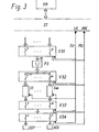
- the function of the invention for a synthesis process is described below with reference to FIG. 3.
- the control device ST is constructed as described with reference to FIG. 2.
- Control criteria SK arrive at the aggregates of a selected system via the control lines SL, and queried reporting criteria MK are transferred from the aggregates to the control device ST via message lines ML.
- the mobile phase M enters the reaction devices S1 to Sm via a first valve arrangement V31 with n valves in the example, via a pump arrangement P31 and via a second valve arrangement V32 with a number of valves corresponding to the number of reaction devices.
- a reaction device S1 to Sm is selected by the m valves of the second valve arrangement V32.
- a third valve arrangement V33 is arranged downstream of the reaction devices S1 to Sm, the m valves of which are always actuated together with the valves of the second valve arrangement V32.
- a further valve arrangement V34 enables the mobile phase to be conducted into individual collecting containers AS1 to ASl.
- the target product e.g. an oligonucleotide is produced here in a reaction device, i.e. in a column Sl to Sm.
- the corresponding valve in the valve arrangement V31 and the corresponding valves in the valve arrangements V32 and V33 are determined by means of corresponding control criteria SK formed by decoding the information taken over from the central control unit PR set.
- the pump arrangement P3 is; if necessary, switched to internal control and the pump parameters are also set.
- the reaction device S1 receives control criteria for setting the loading conditions for the current process or process step are necessary. Reporting criteria are queried by the individual units as described via the reporting lines ML.
- the mobile phase M is not continuously promoted. Rather, the reaction devices S1 to Sm are rather, so to speak, fed, whereupon a reaction then takes place in the reaction devices. Since the loading time is considerably shorter than the reaction time, the pump arrangement P3 can operate a series of reaction devices in succession. This means that the synthesis processes are carried out in parallel in the m reaction devices. In practical operation, e.g. up to 16 oligonucleotides can be produced simultaneously.
- reaction devices are each implemented as so-called individual columns.
- reaction devices can be operated in a so-called column oven common to all reaction devices, the temperature of which can be adjusted and regulated in the manner described by control and reporting criteria.
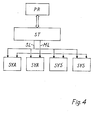
- Fig. 4 shows one possibility of configuring a series of HPLC systems in a manner corresponding to the desired purposes of use.
- two namely the systems designated SYA
- two namely those designated SYS Systems intended for a synthesis process.
- Both the analysis and the synthesis processes run under the control of the central control unit PR, which is provided only once, and also only once provided control part ST simultaneously.
- the same external units reaction devices, pump and valve arrangements
Landscapes
- Chemical & Material Sciences (AREA)
- Analytical Chemistry (AREA)
- Chemical Kinetics & Catalysis (AREA)
- Organic Chemistry (AREA)
- Physics & Mathematics (AREA)
- Health & Medical Sciences (AREA)
- Life Sciences & Earth Sciences (AREA)
- Biochemistry (AREA)
- General Health & Medical Sciences (AREA)
- General Physics & Mathematics (AREA)
- Immunology (AREA)
- Pathology (AREA)
- Apparatus Associated With Microorganisms And Enzymes (AREA)
- Saccharide Compounds (AREA)
- Devices And Processes Conducted In The Presence Of Fluids And Solid Particles (AREA)
- Organic Low-Molecular-Weight Compounds And Preparation Thereof (AREA)
Applications Claiming Priority (2)
| Application Number | Priority Date | Filing Date | Title |
|---|---|---|---|
| DE3401059 | 1984-01-13 | ||
| DE19843401059 DE3401059A1 (de) | 1984-01-13 | 1984-01-13 | Anordnung zur chemischen analyse und synthese |
Publications (1)
| Publication Number | Publication Date |
|---|---|
| EP0158003A1 true EP0158003A1 (fr) | 1985-10-16 |
Family
ID=6224922
Family Applications (2)
| Application Number | Title | Priority Date | Filing Date |
|---|---|---|---|
| EP85100241A Pending EP0158003A1 (fr) | 1984-01-13 | 1985-01-11 | Dispositif pour analyse et synthèse chimique |
| EP19850900662 Withdrawn EP0168451A1 (fr) | 1984-01-13 | 1985-01-11 | Installation de synthese et d'analyse chimique |
Family Applications After (1)
| Application Number | Title | Priority Date | Filing Date |
|---|---|---|---|
| EP19850900662 Withdrawn EP0168451A1 (fr) | 1984-01-13 | 1985-01-11 | Installation de synthese et d'analyse chimique |
Country Status (4)
| Country | Link |
|---|---|
| EP (2) | EP0158003A1 (fr) |
| JP (1) | JPS61501052A (fr) |
| DE (1) | DE3401059A1 (fr) |
| WO (1) | WO1985003129A1 (fr) |
Cited By (1)
| Publication number | Priority date | Publication date | Assignee | Title |
|---|---|---|---|---|
| EP0182755A3 (fr) * | 1984-11-20 | 1989-04-05 | GLAXO S.p.A. | Dispositif sélecteur de la phase mobile pour un appareil chromatographique |
Families Citing this family (1)
| Publication number | Priority date | Publication date | Assignee | Title |
|---|---|---|---|---|
| CH678925A5 (fr) * | 1989-04-04 | 1991-11-29 | Mettler Toledo Ag |
Citations (4)
| Publication number | Priority date | Publication date | Assignee | Title |
|---|---|---|---|---|
| US3985021A (en) * | 1975-11-10 | 1976-10-12 | Varian Associates | High performance liquid chromatography system |
| FR2386342A1 (fr) * | 1977-04-06 | 1978-11-03 | Politechnika Gdanska | Systeme servant a produire une composition programmee de liquide, egalement variable dans le temps, notamment pour la chromatographie liquide a haute pression |
| DE2821005A1 (de) * | 1977-05-13 | 1978-11-23 | Varian Associates | Verfahren zur gradientenproportionierung in einem fluessigkeitschromatographiesystem |
| US4364263A (en) * | 1980-09-15 | 1982-12-21 | Burroughs Wellcome Co. | High pressure liquid chromatographic system |
-
1984
- 1984-01-13 DE DE19843401059 patent/DE3401059A1/de not_active Withdrawn
-
1985
- 1985-01-11 WO PCT/EP1985/000007 patent/WO1985003129A1/fr not_active Ceased
- 1985-01-11 EP EP85100241A patent/EP0158003A1/fr active Pending
- 1985-01-11 JP JP60500543A patent/JPS61501052A/ja active Pending
- 1985-01-11 EP EP19850900662 patent/EP0168451A1/fr not_active Withdrawn
Patent Citations (4)
| Publication number | Priority date | Publication date | Assignee | Title |
|---|---|---|---|---|
| US3985021A (en) * | 1975-11-10 | 1976-10-12 | Varian Associates | High performance liquid chromatography system |
| FR2386342A1 (fr) * | 1977-04-06 | 1978-11-03 | Politechnika Gdanska | Systeme servant a produire une composition programmee de liquide, egalement variable dans le temps, notamment pour la chromatographie liquide a haute pression |
| DE2821005A1 (de) * | 1977-05-13 | 1978-11-23 | Varian Associates | Verfahren zur gradientenproportionierung in einem fluessigkeitschromatographiesystem |
| US4364263A (en) * | 1980-09-15 | 1982-12-21 | Burroughs Wellcome Co. | High pressure liquid chromatographic system |
Non-Patent Citations (1)
| Title |
|---|
| INTERNATIONAL LABORATORY, Mai/Juni 1979, Seiten 95-106; R. FINCHER et al.: "Microprocessor-controlled HPLC" * |
Cited By (1)
| Publication number | Priority date | Publication date | Assignee | Title |
|---|---|---|---|---|
| EP0182755A3 (fr) * | 1984-11-20 | 1989-04-05 | GLAXO S.p.A. | Dispositif sélecteur de la phase mobile pour un appareil chromatographique |
Also Published As
| Publication number | Publication date |
|---|---|
| EP0168451A1 (fr) | 1986-01-22 |
| DE3401059A1 (de) | 1985-07-18 |
| JPS61501052A (ja) | 1986-05-22 |
| WO1985003129A1 (fr) | 1985-07-18 |
Similar Documents
| Publication | Publication Date | Title |
|---|---|---|
| DE69128521T2 (de) | Nichtflüchtige seriell programmierbare Anordnungen | |
| DE69315343T2 (de) | Verfahren fur eingangssignalauflosung von aktiven redundanten prozesssteuerrechnern | |
| EP0024708B1 (fr) | Multiple de canaux temporels pour un système à multiplexage temporel pour la commutation de signaux numériques, en particulier de messages à modulation en delta | |
| DE2256135B2 (de) | Verfahren und Anordnung zum Prüfen von monolithisch integrierten Halbleiterschaltungen | |
| DE3687001T2 (de) | Umschaltmodul in einem signalverteilungssystem. | |
| EP2214068A1 (fr) | Système d'automatisation doté d'un module de matrice programmable | |
| DE2521388A1 (de) | Schaltungsanordnung zur uebertragung digitaler daten | |
| EP0586715B1 (fr) | Procédé de transfert d'informations digitales | |
| DE2158433A1 (de) | Einrichtung und verfahren zum betrieb der einrichtung zur fehlerpruefung und fehlerlokalisierung in einem modularen datenverarbeitungssystem | |
| DE3788617T2 (de) | Vektordatenverarbeitungssystem mit einer E/A-Steuerung für jeden Vektordatenprozessor und einer anderen E/A-Steuerung für mindestens einen anderen Vektordatenprozessor. | |
| DE2415600C2 (fr) | ||
| EP0158003A1 (fr) | Dispositif pour analyse et synthèse chimique | |
| DE3048414A1 (de) | "schaltungsanordnung fuer eine datenverarbeitungsanlage" | |
| DE69027895T2 (de) | Halbleiterspeicher | |
| DE2230727C3 (de) | Schaltungsanordnung zur dynamischen Zuteilung von Speicherzyklen mit Vorrangs steuerung | |
| EP1514277A1 (fr) | Circuit a memoire a acces aleatoire comportant plusieurs bancs et un dispositif auxiliaire pour effectuer des controles | |
| EP0123243A2 (fr) | Dispositif de codage et de décodage pouvant être testé | |
| DE3149926A1 (de) | Programmierbare vergleichsschaltung | |
| EP0404992B1 (fr) | Procédé de fonctionnement à haute disponibilité de dispositifs redondants de traitement de données | |
| DE4342455C2 (de) | Hierarchisches Steuersystem für einen Bagger | |
| DE3827959C2 (fr) | ||
| EP2687930B1 (fr) | Unité d'automatisation destinée à la commande d'un appareil ou d'une installation | |
| DE3806262C1 (en) | Circuit arrangement for monitoring the state of switching points in a digital space-division switching network | |
| DE3733772C2 (de) | Multi-Signalprozessorsystem | |
| DE3010803A1 (de) | Schalteinrichtung fuer ein dreirechner-system in eisenbahnanlagen |
Legal Events
| Date | Code | Title | Description |
|---|---|---|---|
| PUAI | Public reference made under article 153(3) epc to a published international application that has entered the european phase |
Free format text: ORIGINAL CODE: 0009012 |
|
| AK | Designated contracting states |
Designated state(s): AT BE CH DE FR GB IT LI NL SE |
|
| RBV | Designated contracting states (corrected) |
Designated state(s): IT |
|
| STAA | Information on the status of an ep patent application or granted ep patent |
Free format text: STATUS: REQUEST FOR EXAMINATION WAS MADE |
|
| 17P | Request for examination filed |
Effective date: 19860116 |
|
| XX | Miscellaneous (additional remarks) |
Free format text: VERFAHREN ABGESCHLOSSEN INFOLGE VERBINDUNG MIT 85900662.9/0168451 (EUROPAEISCHE ANMELDENUMMER/VEROEFFENTLICHUNGSNUMMER) VOM 24.08.88. |
|
| RIN1 | Information on inventor provided before grant (corrected) |
Inventor name: BLOECKER, HELMUT, DR. DIPL.-CHEM. Inventor name: HENNING, KLAUS-DIETER, DIPL.-ING. Inventor name: ROHWEDDER, KARL, DIPL.-ING. |