EP2214068A1 - Système d'automatisation doté d'un module de matrice programmable - Google Patents
Système d'automatisation doté d'un module de matrice programmable Download PDFInfo
- Publication number
- EP2214068A1 EP2214068A1 EP10150296A EP10150296A EP2214068A1 EP 2214068 A1 EP2214068 A1 EP 2214068A1 EP 10150296 A EP10150296 A EP 10150296A EP 10150296 A EP10150296 A EP 10150296A EP 2214068 A1 EP2214068 A1 EP 2214068A1
- Authority
- EP
- European Patent Office
- Prior art keywords
- module
- processing unit
- automation system
- modules
- terminal
- Prior art date
- Legal status (The legal status is an assumption and is not a legal conclusion. Google has not performed a legal analysis and makes no representation as to the accuracy of the status listed.)
- Ceased
Links
Images

Classifications
-
- G—PHYSICS
- G05—CONTROLLING; REGULATING
- G05B—CONTROL OR REGULATING SYSTEMS IN GENERAL; FUNCTIONAL ELEMENTS OF SUCH SYSTEMS; MONITORING OR TESTING ARRANGEMENTS FOR SUCH SYSTEMS OR ELEMENTS
- G05B19/00—Program-control systems
- G05B19/02—Program-control systems electric
- G05B19/04—Program control other than numerical control, i.e. in sequence controllers or logic controllers
- G05B19/05—Programmable logic controllers, e.g. simulating logic interconnections of signals according to ladder diagrams or function charts
- G05B19/054—Input/output
Definitions
- Automation devices generally have a plurality of input and / or output modules (EM), which are also abbreviated as I / O modules.
- An electronic processing unit in the automation device usually a program-controlled processor, can preferably receive measurement signals from a technical process or a system and output control signals or control commands to operating means of the technical process.
- I / O modules input and / or output modules
- An electronic processing unit in the automation device usually a program-controlled processor, can preferably receive measurement signals from a technical process or a system and output control signals or control commands to operating means of the technical process.
- To connect the I / O modules to these technical resources e.g.
- Automation devices are typically constructed so that direct coupling, i. a kind of linear connection from the electronic processing unit via the I / O modules directly to a terminal area.
- Each I / O module is rigidly assigned to a defined terminal, ie hard-wired to it and thus functionally connected linearly.
- the order, assignment and position between each individual terminal and each individual I / O module are thus defined and fixed. This has the consequence that a change or a free, optional assignment between an I / O module and a terminal or an extension in a mounted system is not possible without costly disconnecting, reconnecting or rebuilding. In the case of limited space available in such a case, such Umrangleiteren may also be impossible.
- DE 10 2004 010 003 A1 is an automation system with connections for field devices, with a feed component and a measuring component for the field devices and with a connection unit for the optional connection of the field device connections to the connections of the feed or measuring components disclosed.
- This automation system already solves the disadvantage of the rigidly assigned terminals to the field devices or to the I / O modules.
- the processing unit can now be program-technically interconnected with the terminal modules via the I / O modules via a programmable matrix module, optimal utilization of the existing I / O modules is not possible.
- the invention is based on the object of further developing an automation system of the type specified above for guiding a technical process in such a way that the existing I / O modules can be optimally utilized.
- the object is achieved with an automation system according to claim 1.
- the processing unit is advantageously designed such that an I / O module with the aid of the programmable matrix module time-controlled multiple terminal blocks can be assigned circuitry, each one terminal block is assigned a time slot. This configuration results in a free, program-controlled assignment of the I / O modules to the terminal blocks.
- the processing unit could, for example, in a hardware pool, which may consist of a number of I / O modules, ask what hardware is currently idle, and then look after them with new tasks, with the required I / O module connected to the terminal blocks becomes. It is thus advantageously possible that, for example, a single I / O module, the process signals of several Scans resources on the respective terminal blocks, for example, in a temporal order staggered or suksessive outputs to this.
- the automation system in the matrix module on a multiplexer is preferably designed as a selection switching network, wherein in a cyclic passage of the multiplexer in different time slots quasi-parallel data streams converted into serial data streams. Accordingly, the different terminal blocks are scanned in temporal succession and their input or output values are passed on to the processing unit via the one I / O module.
- a particular advantage here is that can be solved with this embodiment, an automation task in which previously several I / O modules were necessary, and now the same automation task can be solved with a single I / O module. This results in a cost advantage and a size advantage of the automation device, since it is possible to dispense with complete modules or additional I / O modules.
- Another design option for the automation system to increase the flexibility results when the processing unit is further configured that the I / O module is to be activated via a coupling bus.
- the programmable matrix module operates in the manner of a freely programmable exchange, with which each I / O module can be connected to each terminal block.
- This interconnection assignment can be created, for example, in the configuration of the automation system to a technical system or even flexibly updated during operation.
- the technical Equipment of a system special distributed in the field sensors and actuators can thus be connected during commissioning, for example, taking into account a minimum cable and maneuvering effort on easily accessible terminal blocks.
- the I / O modules can also be arranged without restrictions, eg taking into account the topology of the respective system. This minimizes the risk of assembly and wiring errors, eg confusion in the assignment of I / O modules and terminal block.
- Fig. 1 shows in the form of a block diagram an automation system constructed according to the invention.
- This contains an electronic processing unit 1, for example in the form of a programmable logic controller.
- This processes in a known manner with the aid of application-specific programs signals of a technical process and derives therefrom control signals and commands for influencing the technical process.
- These input and output signals are via a process interface 42, which in the example of the Fig. 1 is shown below, eg exchanged via field buses or simple multi-wire connections with the equipment of the technical system, ie with encoders, sensors, actuators etc.
- data buses, operating and monitoring devices and much more can be connected to the processing unit 1 via communication interfaces.
- Such elements are for reasons of clarity in the block diagram of Fig. 1 not shown.
- a receiving module 2 with slots for I / O modules for example in the form of a rack, an inventive matrix module 3 and an exemplary terminal box 4 with slots for terminals arranged.
- the components 1, 2, 3 and 4 are coupled via a coupling bus with the outputs 5-7 data technically to a first data bus interface 11 of the electronic processing unit 1.
- the coupling bus is thus looped through the receiving module 2 via a first data interface 21, a backplane bus 23 and a second data interface 22.
- the receiving module 2 provides slots for I / O modules, of which in the example of Fig. 1 the slots 24 are empty and the remaining slots with I / O modules 25a - 25e are occupied.
- the I / O modules may preferably be so-called intelligent interface modules.
- Modules of this type have processing means, with their computing power a pre- and post-processing of input and output signals of the technical process and thus a discharge of the electronic processing unit 1 is possible. Examples of modules of this type can be called input and output modules for binary or analog process signals.
- each I / O module is either dedicated to one or more resources of the technical process, or are provided by one or more resources. It is thus necessary to assign the outputs of the I / O modules in the receiving module 2 to the leading to the respective resources cable connections of the technical process.
- These cable connections are in the example of Fig. 1 placed on terminal blocks at the process interface 42, which are brought together in a terminal box 4.
- the coupling bus at the outlet 7 is data-technically looped via a data bus interface 41 in the terminal box 4 and looped through a backplane bus 43.
- the terminal box 4 provides slots for terminal blocks, in the example of the Fig. 1 the slots 44 are unoccupied and the remaining slots are occupied by terminal blocks 45a-45e.
- the terminal blocks can be equipped with different cable connection technology, eg with screw contacts or spring-loaded contacts.
- a matrix module 3 is arranged between the receiving module 2 and terminal box 4, a matrix module 3. This is connected by way of example via data interfaces 32a, 32b to the outlets of the coupling bus 6, 7. Furthermore, it is connected to the coupling bus 5 via a data interface 31.
- the matrix module 3 can be programmed by the processing unit 1 in such a way that one or more terminal modules 45a-45e are dynamically assigned one or more I / O modules 25a-25e in terms of circuitry.
- program links are exemplified, with program path 33a the module 25a with terminal 45b, program path 33b the module 25b with terminal 45a, program path 33c the module 25d with terminal 45c, program path 33d the module 25e with terminal 45d and program path 33e module 25c with Terminal 45e linked.
- program links are only examples and may possibly be dynamically adjusted during operation by the processing unit 1.
- the processing unit can dynamically change the assigned terminal block, which can no longer receive or transfer process signals to the processing unit 1, with the aid of the programmable matrix module Assign a module in terms of circuitry. In this way, the continued operation of the automation system can be made possible. For example, as part of a redundant system instrumentation, more I / O modules must be plugged into the recording module 2 than are needed for normal operation. In this case, the processing unit would dynamically assign the affected terminal block to a previously unused I / O module.
- the processing unit may also detect the failure of a resource of the technical process, e.g. a sensor or actuator can detect.
- the processing unit dynamically changes the affected I / O module, which can no longer transfer process signals to or from the technical process due to the failure, with the aid of the programmable matrix module Assigning the terminal block in terms of circuitry. If this is connected to at least partially functional equipment of the plant, it may be possible to maintain its operation or at least to effect orderly decommissioning using substitute process signals.
- the technical process is equipped with reserve resources, e.g. with replacement pumps or emergency drives, it is advantageous then the processing unit to the affected I / O module dynamically assigns a terminal block interconnected to which a redundant equipment of the technical system is connected.
- the invention even makes it possible for the processing unit to dynamically allocate several terminal blocks dynamically to an I / O module with the aid of the programmable matrix module.
- the I / O module activates these terminal blocks, in particular for the input and output of process signals, advantageously cyclically.
- Such a case can occur in practice, in particular, when terminals of the technical process are connected to terminal blocks whose states are only slowly variable compared to the processing speed of the I / O module.
- Equipment of this kind can eg heaters and the be connected temperature transmitter.
- a single I / O module interrogates the process signals of several resources staggered at the respective terminal blocks, for example in a temporal order, or outputs them successively to them.
- the matrix module then additionally has the function of a multiplexer.
- the processing unit dynamically assigns a single terminal block to a plurality of I / O modules using the programmable matrix module.
- the I / O modules activate this terminal block, in particular for input and output of process signals, cyclically.
- a resource of this kind may e.g. be a variable speed drive and an attached speed encoder.
- a plurality of I / O modules to receive the fast variable process signal of the single resource from the respective terminal block, e.g. in a temporal order by means of a time slot method query or output to this.
- the matrix module then additionally has the function of a multiplexer.
- the processing unit in particular during startup, dynamically detects the existing I / O modules in a first search and, in a second search, the resources of the technical process connected to the terminal blocks.
- the I / O modules and resources are detected by type and slot.
- the activatable rows and columns in the programmable matrix module are virtually determined.
- the processing unit can now dynamically the interconnection assignment of one or more terminal blocks with one or more I / O modules in particular depending on an application-dependent control program automatically.
- the processing unit may preferably perform this search at a first startup, but also at a later time or repeatedly.
- the automation system first recognizes the installed I / O modules according to type and arrangement, ie the assignment of the slots of the recording module 2 in FIG Fig. 1 with a specific I / O module.
- a further search then connected to the respective terminal blocks in the terminal box 4 resources of the technical process, in particular the sensors and actuators detected.
- the invention facilitates the use of dynamic programming by achieving a quasi-neural network of I / O modules with the terminal blocks. This allows for more object-oriented execution of control programs such that important performance features of an automation system, such as an automation system, are eliminated. Redundancy, processing speed, accuracy, scalability are better than before.
- the free assignment of the I / O modules to the process terminals using the program-controlled matrix module also enables the implementation of new functions in a controller.
- the processing unit may be e.g. in the hardware pool ask which I / O modules are temporarily idle. These can then be loaded with new or alternative control or measuring tasks and switched through with the matrix module to the required terminals.
- These dynamic assignments can also be stochastic forward-looking or self-optimizing.
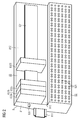
- Fig. 2 shows an exemplary structure of a separate interface module 8 for an automation system.
- the housing 81 of the interface module is equipped on the back 811 with engagement means for holding a DIN rail.
- the front of the housing 81 is a terminal area 812 having an interface plane 83 in an upper area and a wiring plane 82 in a lower area educated.
- the wiring plane 82 has, for example, a plurality of wiring terminals 821. At this can be launched by a technical system brought up process signal lines.
- Fig. 2 are each two adjacent rows of 6 vertically stacked terminals grouped into a terminal block.
- Fig. 2 are each two adjacent rows of 6 vertically stacked terminals grouped into a terminal block.
- the three slots located at the left end of the interface plane 83 are each equipped with one I / O module 832a, 832b, 832c, while the three further slots following to the right are unoccupied. This is followed by another I / O module 832d.
- the I / O modules are data technically coupled to each other via the backplane bus 831. This also forms the connection to a processing unit, not shown.
- the assignment of the I / O modules 832a-832d to selected terminal blocks takes place according to the present invention with the aid of a programmable matrix module. This is integrated in the housing 81 and connected in this way via the backplane bus 831 with the I / O modules 832a-832d, a processing unit and the wiring terminals 821.
Landscapes
- Physics & Mathematics (AREA)
- General Physics & Mathematics (AREA)
- Engineering & Computer Science (AREA)
- Automation & Control Theory (AREA)
- Programmable Controllers (AREA)
Applications Claiming Priority (1)
| Application Number | Priority Date | Filing Date | Title |
|---|---|---|---|
| DE102009007215A DE102009007215A1 (de) | 2009-02-03 | 2009-02-03 | Automatisierungssystem mit einem programmierbaren Matrixmodul |
Publications (1)
| Publication Number | Publication Date |
|---|---|
| EP2214068A1 true EP2214068A1 (fr) | 2010-08-04 |
Family
ID=42173475
Family Applications (1)
| Application Number | Title | Priority Date | Filing Date |
|---|---|---|---|
| EP10150296A Ceased EP2214068A1 (fr) | 2009-02-03 | 2010-01-08 | Système d'automatisation doté d'un module de matrice programmable |
Country Status (4)
| Country | Link |
|---|---|
| US (1) | US20100204806A1 (fr) |
| EP (1) | EP2214068A1 (fr) |
| CN (1) | CN101794134A (fr) |
| DE (1) | DE102009007215A1 (fr) |
Cited By (2)
| Publication number | Priority date | Publication date | Assignee | Title |
|---|---|---|---|---|
| WO2011098543A1 (fr) * | 2010-02-12 | 2011-08-18 | Phoenix Contact Gmbh & Co. Kg | Module logique de commutation |
| DE102011079890A1 (de) * | 2011-07-27 | 2013-01-31 | Codewrights Gmbh | System und Verfahren zur Bedienung von Feldgeräten in einer Automatisierungsanlage |
Families Citing this family (7)
| Publication number | Priority date | Publication date | Assignee | Title |
|---|---|---|---|---|
| SG180055A1 (en) * | 2010-10-29 | 2012-05-30 | Rockwell Automation Asia Pacific Business Ctr Pte Ltd | Industrial controller interface for plug-in i/o modules |
| EP2456010A1 (fr) | 2010-11-23 | 2012-05-23 | Saia-Burgess Controls AG | Composant de réseau comprenant un dispositif électrique |
| JP5954338B2 (ja) * | 2014-01-14 | 2016-07-20 | 横河電機株式会社 | 計装システム及びその保守方法 |
| EP3214512B1 (fr) * | 2016-03-02 | 2018-04-25 | Siemens Aktiengesellschaft | Systeme de commande redondant pour un actionneur et son procede de commande redondant |
| GB2567926B (en) * | 2017-09-13 | 2022-10-26 | Fisher Rosemount Systems Inc | System and methods for enhanced modular controller port to port communication |
| US10551815B2 (en) * | 2017-09-13 | 2020-02-04 | Fisher-Rosemount Systems, Inc. | Systems and methods for enhanced modular controller port to port communication |
| DE102019109184A1 (de) * | 2019-04-08 | 2020-10-08 | Teutloff Technische Akademie gGmbH | Modellfabrik |
Citations (3)
| Publication number | Priority date | Publication date | Assignee | Title |
|---|---|---|---|---|
| DE3603142A1 (de) * | 1986-02-01 | 1987-08-06 | Degussa | Vorrichtung und verfahren zum regeln und steuern von chemischen und physikalischen vorgaengen in einer vielzahl von dafuer geeigneten apparaten |
| EP1450223A1 (fr) * | 2003-02-24 | 2004-08-25 | Hartmut B. Dr. Brinkhus | Circuit d'interface universel configurable pour formé l'interface d'entrée/sortie d'un processus |
| DE102004010003A1 (de) * | 2004-03-01 | 2005-09-29 | Siemens Ag | Automatisierungssystem und Verfahren zur Erkennung und Korrektur von Anschlussfehlern |
Family Cites Families (10)
| Publication number | Priority date | Publication date | Assignee | Title |
|---|---|---|---|---|
| US4799159A (en) * | 1985-05-30 | 1989-01-17 | Honeywell Inc. | Digital automatic flight control system with disparate function monitoring |
| US4965717A (en) * | 1988-12-09 | 1990-10-23 | Tandem Computers Incorporated | Multiple processor system having shared memory with private-write capability |
| DE29520572U1 (de) * | 1995-12-27 | 1996-03-07 | Siemens AG, 80333 München | Anordnung mit Ein- und Ausgabeeinheiten |
| US5764878A (en) * | 1996-02-07 | 1998-06-09 | Lsi Logic Corporation | Built-in self repair system for embedded memories |
| US6098116A (en) * | 1996-04-12 | 2000-08-01 | Fisher-Rosemont Systems, Inc. | Process control system including a method and apparatus for automatically sensing the connection of devices to a network |
| US6438670B1 (en) * | 1998-10-02 | 2002-08-20 | International Business Machines Corporation | Memory controller with programmable delay counter for tuning performance based on timing parameter of controlled memory storage device |
| US6631134B1 (en) * | 1999-01-15 | 2003-10-07 | Cisco Technology, Inc. | Method for allocating bandwidth in an optical network |
| EP1394559A1 (fr) * | 2002-08-27 | 2004-03-03 | Siemens Aktiengesellschaft | Procédé et dispositif pour détecter et corriger des erreurs de lignes défectueuses |
| DE10316694A1 (de) * | 2003-04-10 | 2004-10-28 | Intedis Gmbh & Co. Kg | Leitungssystem in einem Fahrzeug |
| JP4614085B2 (ja) * | 2005-08-30 | 2011-01-19 | 株式会社デンソー | 車載用電子機器の接続システム |
-
2009
- 2009-02-03 DE DE102009007215A patent/DE102009007215A1/de not_active Ceased
-
2010
- 2010-01-08 EP EP10150296A patent/EP2214068A1/fr not_active Ceased
- 2010-02-03 US US12/699,696 patent/US20100204806A1/en not_active Abandoned
- 2010-02-03 CN CN201010110867A patent/CN101794134A/zh active Pending
Patent Citations (3)
| Publication number | Priority date | Publication date | Assignee | Title |
|---|---|---|---|---|
| DE3603142A1 (de) * | 1986-02-01 | 1987-08-06 | Degussa | Vorrichtung und verfahren zum regeln und steuern von chemischen und physikalischen vorgaengen in einer vielzahl von dafuer geeigneten apparaten |
| EP1450223A1 (fr) * | 2003-02-24 | 2004-08-25 | Hartmut B. Dr. Brinkhus | Circuit d'interface universel configurable pour formé l'interface d'entrée/sortie d'un processus |
| DE102004010003A1 (de) * | 2004-03-01 | 2005-09-29 | Siemens Ag | Automatisierungssystem und Verfahren zur Erkennung und Korrektur von Anschlussfehlern |
Non-Patent Citations (2)
| Title |
|---|
| KARSTEN A: "INDIVIDUALISTEN. ÖMINIKOPPLER FUER DIE INTERFACETECHNIK", ELEKTROTECHNIK, 331951 1, vol. 76, no. 4, 14 April 1994 (1994-04-14), pages 40,42, XP000447795, ISSN: 1431-9578 * |
| VON KARSTEN A: "Individualisten, Minikoppler für die Interfacetechnik", ELEKTROTECHNIK, vol. 76, no. 4, 14 April 1994 (1994-04-14), pages 40,42 |
Cited By (2)
| Publication number | Priority date | Publication date | Assignee | Title |
|---|---|---|---|---|
| WO2011098543A1 (fr) * | 2010-02-12 | 2011-08-18 | Phoenix Contact Gmbh & Co. Kg | Module logique de commutation |
| DE102011079890A1 (de) * | 2011-07-27 | 2013-01-31 | Codewrights Gmbh | System und Verfahren zur Bedienung von Feldgeräten in einer Automatisierungsanlage |
Also Published As
| Publication number | Publication date |
|---|---|
| DE102009007215A1 (de) | 2010-08-05 |
| US20100204806A1 (en) | 2010-08-12 |
| CN101794134A (zh) | 2010-08-04 |
Similar Documents
| Publication | Publication Date | Title |
|---|---|---|
| EP2214068A1 (fr) | Système d'automatisation doté d'un module de matrice programmable | |
| EP1174781B1 (fr) | Appareil de transmission de signal | |
| DE19512372A1 (de) | Einrichtung zur eigensicheren Signalanpassung | |
| EP2067081B1 (fr) | Procédé destiné à la synchronisation de deux dispositifs de commande et dispositif d'automatisation monté de manière redondante | |
| EP1450223A1 (fr) | Circuit d'interface universel configurable pour formé l'interface d'entrée/sortie d'un processus | |
| DE102006020070A1 (de) | Einrichtung zur Ferdiagnose eines Feldgeräts | |
| DE102016000126B4 (de) | Serielles Bussystem mit Koppelmodulen | |
| DE4216242C2 (de) | Identifizierung von Sensoren / Aktuatoren in Bussystemen | |
| EP2510412B1 (fr) | Module électronique | |
| DE102007043769B4 (de) | Gerät, Verfahren zur Adressierung, Umrichter und Verfahren zur sicheren Datenübertragung | |
| EP3039494B1 (fr) | Système d'automatisation | |
| DE19917102A1 (de) | Projektierungs- und Diagnoseeinrichtung für eine elektrische Anlage | |
| EP0966704A1 (fr) | Dispositif programmable pour repartir des signaux de commande electriques sur des appareils techniques | |
| EP3047635A1 (fr) | Coupleur de bus de terrain pour la connexion de modules à un bus de terrain et procédé d'adressage de ces modules | |
| EP4078302B1 (fr) | Appareil d'échange de signaux entre un dispositif de commande et des dispositifs de terrain | |
| WO2009097871A1 (fr) | Système de communication et procédé de communication avec maîtres de groupe pour la transmission de données série dans le domaine de l'automatisation | |
| DE4013815C2 (de) | Steuerschaltung für Maschinen | |
| DD254454A5 (de) | Vorrichtung und verfahren zum regeln und steuern von chemischen und physikalischen vorgaengen in einer vielzahl von dafuer geeigneten apparaten | |
| DE2525438A1 (de) | Ueberwachungsanordnung zur ueberwachung zentraler einrichtungen | |
| DE4107007A1 (de) | Elektronisches geraet | |
| DE10328384B4 (de) | Steuerbare Einrichtung zur sicherheitsgerichteten Auswahl | |
| DE102004027918B4 (de) | Power-Baustein | |
| DE3010803A1 (de) | Schalteinrichtung fuer ein dreirechner-system in eisenbahnanlagen | |
| DD226680A1 (de) | Hierarchisch und rechundant aufbaubares prozessmikrorechnersystem mit hoher stoersicherheit | |
| DE29924799U1 (de) | Projektierungs- und Diagnoseeinrichtung für eine elektrische Anlage |
Legal Events
| Date | Code | Title | Description |
|---|---|---|---|
| PUAI | Public reference made under article 153(3) epc to a published international application that has entered the european phase |
Free format text: ORIGINAL CODE: 0009012 |
|
| AK | Designated contracting states |
Kind code of ref document: A1 Designated state(s): AT BE BG CH CY CZ DE DK EE ES FI FR GB GR HR HU IE IS IT LI LT LU LV MC MK MT NL NO PL PT RO SE SI SK SM TR |
|
| AX | Request for extension of the european patent |
Extension state: AL BA RS |
|
| 17P | Request for examination filed |
Effective date: 20101220 |
|
| 17Q | First examination report despatched |
Effective date: 20120222 |
|
| RAP1 | Party data changed (applicant data changed or rights of an application transferred) |
Owner name: SIEMENS AKTIENGESELLSCHAFT |
|
| STAA | Information on the status of an ep patent application or granted ep patent |
Free format text: STATUS: THE APPLICATION HAS BEEN REFUSED |
|
| 18R | Application refused |
Effective date: 20121213 |