EP0158081A2 - Verdampfer, insbesondere für Klimaanlagen in Kraftfahrzeugen - Google Patents
Verdampfer, insbesondere für Klimaanlagen in Kraftfahrzeugen Download PDFInfo
- Publication number
- EP0158081A2 EP0158081A2 EP85102080A EP85102080A EP0158081A2 EP 0158081 A2 EP0158081 A2 EP 0158081A2 EP 85102080 A EP85102080 A EP 85102080A EP 85102080 A EP85102080 A EP 85102080A EP 0158081 A2 EP0158081 A2 EP 0158081A2
- Authority
- EP
- European Patent Office
- Prior art keywords
- distribution
- pipe
- channels
- evaporator according
- evaporator
- Prior art date
- Legal status (The legal status is an assumption and is not a legal conclusion. Google has not performed a legal analysis and makes no representation as to the accuracy of the status listed.)
- Granted
Links
- 238000004378 air conditioning Methods 0.000 title claims abstract description 5
- 238000009826 distribution Methods 0.000 claims abstract description 71
- 239000003507 refrigerant Substances 0.000 claims abstract description 36
- 230000001914 calming effect Effects 0.000 claims abstract description 35
- 239000012530 fluid Substances 0.000 claims description 6
- 239000012071 phase Substances 0.000 description 4
- 238000004519 manufacturing process Methods 0.000 description 3
- 238000009827 uniform distribution Methods 0.000 description 3
- 238000010276 construction Methods 0.000 description 2
- 239000007788 liquid Substances 0.000 description 2
- 238000007789 sealing Methods 0.000 description 2
- 230000009172 bursting Effects 0.000 description 1
- 230000002349 favourable effect Effects 0.000 description 1
- 239000007792 gaseous phase Substances 0.000 description 1
- 238000009499 grossing Methods 0.000 description 1
- 238000009434 installation Methods 0.000 description 1
- 239000000203 mixture Substances 0.000 description 1
- 238000013021 overheating Methods 0.000 description 1
- 238000000926 separation method Methods 0.000 description 1
Images


Classifications
-
- F—MECHANICAL ENGINEERING; LIGHTING; HEATING; WEAPONS; BLASTING
- F28—HEAT EXCHANGE IN GENERAL
- F28F—DETAILS OF HEAT-EXCHANGE AND HEAT-TRANSFER APPARATUS, OF GENERAL APPLICATION
- F28F9/00—Casings; Header boxes; Auxiliary supports for elements; Auxiliary members within casings
- F28F9/02—Header boxes; End plates
- F28F9/026—Header boxes; End plates with static flow control means, e.g. with means for uniformly distributing heat exchange media into conduits
- F28F9/027—Header boxes; End plates with static flow control means, e.g. with means for uniformly distributing heat exchange media into conduits in the form of distribution pipes
-
- F—MECHANICAL ENGINEERING; LIGHTING; HEATING; WEAPONS; BLASTING
- F25—REFRIGERATION OR COOLING; COMBINED HEATING AND REFRIGERATION SYSTEMS; HEAT PUMP SYSTEMS; MANUFACTURE OR STORAGE OF ICE; LIQUEFACTION SOLIDIFICATION OF GASES
- F25B—REFRIGERATION MACHINES, PLANTS OR SYSTEMS; COMBINED HEATING AND REFRIGERATION SYSTEMS; HEAT PUMP SYSTEMS
- F25B39/00—Evaporators; Condensers
- F25B39/02—Evaporators
- F25B39/028—Evaporators having distributing means
-
- F—MECHANICAL ENGINEERING; LIGHTING; HEATING; WEAPONS; BLASTING
- F25—REFRIGERATION OR COOLING; COMBINED HEATING AND REFRIGERATION SYSTEMS; HEAT PUMP SYSTEMS; MANUFACTURE OR STORAGE OF ICE; LIQUEFACTION SOLIDIFICATION OF GASES
- F25B—REFRIGERATION MACHINES, PLANTS OR SYSTEMS; COMBINED HEATING AND REFRIGERATION SYSTEMS; HEAT PUMP SYSTEMS
- F25B41/00—Fluid-circulation arrangements
- F25B41/40—Fluid line arrangements
- F25B41/42—Arrangements for diverging or converging flows, e.g. branch lines or junctions
- F25B41/45—Arrangements for diverging or converging flows, e.g. branch lines or junctions for flow control on the upstream side of the diverging point, e.g. with spiral structure for generating turbulence
Definitions
- the invention relates to an evaporator, in particular for air conditioning systems in motor vehicles, of the type specified in the preamble of claim 1.
- an evaporator is known for example from DE-OS 31 36 374.
- the refrigerant segregates into a liquid and a gaseous phase.
- the result of this is that when the total volume is divided between the different pipe strings, there is an uneven division and thus the pipe strands are applied differently. This leads to overheating of some evaporator lines compared to others, which negatively affects the control behavior of the system and also the evaporator performance.
- the invention is based on the insight that the mass flow of a refrigerant as a result of Radialbeschleuni structural conditions and the inertia undergoes at least partial separation of the phases, by a smoothing section in a form suitable for uniform distribution of flow form, in particular as regards the uniform impingement of the flow cross-section, taken becomes.
- the length of the calming section at least the fold 7, preferably 1 0 - to 12-times the diameter of the feed pipe, is.
- it is expedient to form the calming section by a tubular body arranged centrally in the distribution pipe and to provide an annular space surrounding the calming section as the distribution chamber.
- a number of channels corresponding to the number of pipe strings is formed in the annular space, each at the end of the calming section or behind start the deflecting means and lead to one pipe string each.
- These channels are preferably designed to be coiled, which is particularly favorable, in particular because of the gradual change in direction and for reasons of production engineering.
- the distribution space comprises a plurality of separate channels which are initially parallel to the longitudinal axis of the distribution tube and then, with the exception of one channel, in the circumferential direction of the Distribution pipe run so that the ends of all channels are arranged on an axis parallel to the distribution pipe.
- a fluid distributor at the end of the calming section, from which the individual channels originate.
- a flow distributor is preferably designed in the manner of a Venturi nozzle, as has been used for a long time in evaporators.
- the venturi distributor is arranged in front of the deflecting means for the refrigerant.
- a particularly simple arrangement of the tubular body consists in that it extends until shortly before a plate closing the distribution tube. This free end of the tube body is fixed in its central position by radial, outwardly directed tabs, which are supported on the inner wall of the distribution tube.
- a particularly simple and inexpensive design of the means for deflecting the refrigerant flow consists in that the end of the distribution pipe is spherical. Another particularly simple arrangement of the means for deflecting the refrigerant flow is that the end of the calming section and the distribution pipe is closed and in the wall separating the calming section from the distribution pipe, radial openings are provided for the passage of the refrigerant.
- a terms of simple construction and easy assembly, preferred embodiments of the calming section and the distributing channels is that the channels between radial ribs which are integral with the tubular body and the wall of the V ER- partialtube abut, are formed.
- FIG. 1 denotes an evaporator, which essentially consists of an evaporator block comprising a plurality of tubes 2 and ribs 3 arranged transversely thereto.
- the tubes 2 of a row are each connected to the tubes 2 of a next row by means of deflection bends 4, so that the pipes connected to one another form a pipe string from the first to the last row of pipes
- a distribution pipe 5 to which the pipes 2 of the first pipe row are connected is arranged above the pipe ends of the first pipe row, the distribution pipe 5 is closed at one end and the other The end is connected to an expansion valve 7 via a feed pipe 6.
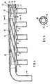
- FIG. 2 shows a section through a distribution pipe 5, to which the pipes 2 of the evaporator are connected.
- the distribution pipe 5 is closed at one end by means of a plate 9 which is shaped in such a way that it has in its center a cone 11 directed into the distribution pipe 5 and around it an outward annular recess 10.
- a pipe body 12 is arranged centrally in the distribution pipe 5 and has a sculpted end 13 on the side to which the supply pipe 6 is connected, into which the supply pipe 6 projects.
- the tubular body 12 extends evenly up to just before the plate 9 and is supported at this end by a few radially outwardly directed tabs 14 on the inner wall of the distribution tube 5. Between Tabs 14 have openings through which the refrigerant can pass.
- the tubular body 12 thus forms a calming section 15, which extends over the entire length from the end 13 which is topped up to the end adjacent to the plate 9. Between the tube body 12 and the tube 5 there is an annular space 16 from which the evaporator tubes 2 originate.
- the refrigerant supplied through the feed pipe 6 is passed through the calming section 15 and deflected on the plate 9 into the annular space 16 and divided into the annular space 16 acting as a distribution space between the parallel evaporator tubes 2.
- FIG. 3 shows an embodiment variant of the end of the distribution pipe 5 shown on the right in FIG.
- the tubular body 12 forming the calming section 15 extends to and is attached to a plate 17 which closes the distribution tube 5 and is essentially flat.
- the angled tabs 14 according to FIG. 2 are not required to support the tubular body 12.
- several openings 18 are provided near the plate 17 in the tubular body 12, which are evenly distributed over the circumference of the tubular body 12.
- FIG. 4 shows a section through a distribution pipe 5, in which a tubular body 19 is arranged, which on its lateral surface 5 has radial ribs 20, which run helically along the lateral surface of the tubular body 19.
- the ribs 20 project up to the wall of the distribution pipe 5 and thus form between the tubular body 19 and the distribution pipe 5 a number of coiled channels corresponding to the number of the ribs 20
- a fluid distributor 22 which is designed in the manner of a Venturi nozzle and consists of two parts 23 and 25.
- 23 denotes a sleeve pressed into the tubular body 19, which, viewed in the direction of flow, initially has a taper and then a conical widening.
- a cone designated 25 projects into this conical enlargement and is a component of a disk 24 closing the distribution tube 5.
- deflection channels 26 are provided in the disk, which overlap the end of the tubular body 19 and thus deflect the refrigerant from the flow distributor 22 into the channels 21.
- Figure 5 shows a section along the line VV in Figure 4. From this illustration it can be seen that within the distribution tube 5, the tubular body 19 is arranged with five radial ribs 2o, the ribs 2o made in one piece with the tubular body 19 on the wall of the Distributor tube 5 abut. A channel 21 is formed between two ribs 2o.
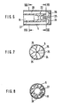
- FIG. 6 shows an embodiment variant of FIG. 4, in which the distribution pipe 5 is likewise closed by a disk 24 with a central cone 25 and deflection channels 26.
- the distribution tube 5 there is a cylindrical body 27, which is preferably made of plastic and which ends near the disc 24.
- the deflection channels 26 overlap the end of the body 27, which at the end of the calming section 15 has a cone tapering the flow cross section and then an expanding cone.
- the aforementioned cone 25 projects into the expanding cone the disc 24 and thus forms the fluid distributor; 22.
- a plurality of axially extending channels 28 are arranged on the lateral surface of the cylindrical body 27 and lead to the connections of the evaporator tubes 2.
- FIG. 7 shows a section along the line VII-VII in FIG. 6.
- the disk 24 closing the distribution tube is inserted, in the middle of which the tip of the cone 25 is present.
- the disk 24 has five deflection channels 26 arranged in a star shape.
- FIG. 8 shows a section along the line VIII-VIII in FIG. 6. From this illustration it can be seen that a cylindrical body 27 is arranged in the distribution tube 5, in the middle of which a calming section 15 forms a central bore. Five channels 28, which are covered by the distribution tube 5, are arranged on the circumferential surface of the cylindrical body 27 and are distributed uniformly over the circumference.
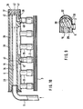
- FIG. 9 shows the end of the distribution pipe 5 which is remote from the feed pipe 6 and in which a cylindrical body 29 with a central bore is inserted as a calming section 15.
- the body 29 On the lateral surface, the body 29 has a plurality of helically extending channels 3o, which are formed between ribs 31 of the body 29 and are covered by the distribution pipe 5. 3o The channels each leading into the region of a terminal of Verdam p ferrohre 2.
- the manifold 5 has a spherically formed end of the pipe 32. The end of the body 29 is at a distance from this spherical end 32, so that an unimpeded passage of the refrigerant from the calming section into the distribution channels 3o is possible.
- FIG. 10 shows the entire longitudinal section through a distributor plug 5 with a body 33 located therein, which has a central bore 34 which extends over the entire length of the body 33 and serves as a calming section 15 for the refrigerant.
- 6 to the state shown in the end shown on the left 1 0 of the body 33 opens the supply pipe into the bore 34 to the manifold six pipe stub 35 are arranged at a uniform distance to which the transversely extending through fins 3 evaporator tubes 2 are connected.
- the end of the distribution pipe 5 which is remote from the feed pipe 6 is closed by a disk 36 which is provided on its outer circumferential surface with a sealing ring 37.
- each channel 39 extending in the longitudinal direction of the body are distributed over a circumference, but at a radial distance from the bore 34 and the lateral surface 38 of the body 33.
- each of the channels formed by the portions 39, 4o, 41 opens at one of which is arranged on an axis parallel of the manifold 5 connecting piece 35th
- a cone 42 is arranged which protrudes a little into the central bore 34 and whose outer surface merges into deflection channels 43, the outer ends of which are congruent with the channels 39 in the body 33.
- the refrigerant is thus led from the expansion valve through the feed pipe 6 into the calming section 15. Due to the The radii of curvature of the feed pipe 6 are narrow, so that the wet steam mixture segregates, so that the refrigerant is at least partially in two phases. In the calming section 15, a uniform distribution of the mass flow over the cross section of the calming section 15 is then achieved, so that the refrigerant is also divided into the individual tube strings of the evaporator into individual streams with the same mass.
Landscapes
- Engineering & Computer Science (AREA)
- Physics & Mathematics (AREA)
- Mechanical Engineering (AREA)
- Thermal Sciences (AREA)
- General Engineering & Computer Science (AREA)
- Heat-Exchange Devices With Radiators And Conduit Assemblies (AREA)
- Air-Conditioning For Vehicles (AREA)
Abstract
Description
- Die Erfindung bezieht sich auf einen Verdampfer, insbesondere für Klimaanlagen in Kraftfahrzeugen, der im Oberbegriff des Patentanspruchs 1 angegebenen Gattung. Ein derartiger Verdampfer ist beispielsweise aus der DE-OS 31 36 374 bekannt.
- Bei Verdampfern, die unter beengten Raumverhältnissen eingebaut werden sollen, wie dies beispielsweise bei Kraftfahrzeug-Klimaanlagen der Fall ist, besteht das Problem, daß das Expansionsventil nicht unmittelbar vor dem Verteilrohr angeordnet werden kann. Die Verbindungsleitung zwischen Expansionsventil und Verteilrohr ist wegen der beengten Raumverhältnisse teilweise gebogen, wobei häufig kleine Krümmungsradien auftreten.
- Aufgrund des Abstandes zwischen Expansionsventil und Verteilrohr und insbesondere wegen der durch die Krümmung des Zuleitungsrohres bedingten Richtungsänderung des Kältemittels entsteht eine Entmischung des Kältemittels in eine flüssige und eine gasförmige Phase. Dies hat zur Folge, daß bei der Aufteilung des Gesamtvolumens auf die verschiedenen Rohrstränge eine mengenungleiche Teilung erfolgt und somit die Rohrstränge unterschiedlich beaufschlagt werden. Dies führt zu einer Überhitzung einiger Verdampferstränge gegenüber anderen, was das Regelverhalten der Anlage und auch die Verdampferleistung negativ beeinflußt.
- Zur Erzielung einer gleichmäßigen Kältemittelströmung vor der Aufteilung in die einzelnen Rohrstränge des Verdampfers wurde daher bereits in der deutschen Patentanmeldung P 33 27 179.8 vorgeschlagen, unmittelbar vor dem Verteilrohr im Kältemittelstrom ein Verwirbelungselement anzuordnen, damit ein Zerplatzen der aus Kältemitteldampf und Kältemittelflüssigkeit bestehenden Zwei-Phasen-Strömung und einer Verwirbelung der beiden Phasen erreicht wird. Die Anordnung einer derartigen Wirbelzelle hat zu sehr guten Ergebnissen hinsichtlich einer gleichmäßigen Beaufschlagung der Verdampferrohre und somit auch zu einer guten Verdampferleistung geführt. Eine Wirbelzelle benötigt jedoch trotz der relativ geringen Abmessungen einen gewissen Bauraum direkt vor dem Verteilrohr, der nicht überall zur Verfügung steht, und außerdem entstehen zusätzliche Kosten für die Fertigung und Montage einer solchen Wirbelzelle.
- Es ist daher die Aufgabe der vorliegenden Erfindung, einen Verdampfer der im Oberbegriff des Patentanspruchs 1 angegebenen Gattung derart weiterzubilden, daß mit einfachen Mitteln und ohne zusätzlichem Bauraum eine Anordnung zur Erzeugung einer gleichmäßigen Aufteilung des Kältemittels auf die Verdampferrohre erreicht wird. Darüber hinaus soll die Anordnung keine zusätzlichen Herstellungskosten verursachen und die Zahl der Rdhrverbindungen auf ein Minimum begrenzen.
- Diese Aufgabe wird bei einem Verdampfer der bezeichneten Art erfindungsgemäß durch die kennzeichnenden Merkmale des Patentanspruchs 1 gelöst.
- Der Erfindung liegt die Erkenntnis zugrunde, daß der Massenstrom eines Kältemittels, das infolge von Radialbeschleunigungen und Massenträgheit eine zumindest teilweise Trennung der Phasen erfährt, durch eine Beruhigungsstrecke in eine für die gleichmäßige Verteilung geeignete Strömungsform, insbesondere hinsichtlich der gleichmäßigen Beaufschlagung des Strömungsquerschnitts, gebracht wird.
- Eine bevorzugte Weiterbildung des Erfindungsgegenstandes besteht darin, daß die Länge der Beruhigungsstrecke mindestens das 7-fache, vorzugsweise das 10- bis 12-fache des Durchmessers des Zuleitungsrohres, beträgt. Um einen möglichst einfachen und kostengünstigen Aufbau zu erreichen, ist es zweckmäßig, die Beruhigungsstrecke=durch einen zentrisch im Verteilrohr angeordneten Rohrkörper zu bilden und als Verteilraum einen die Beruhigungsstrecke umgebenden Ringraum vorzusehen.
- Damit nach der Umlenkung des Kältemittels von der Beruhigungsstrecke in den Verteilraum eine gleichmäßige Beaufschlagung aller Verdampferrohre mit Kältemittel gewährleistet ist, wird vorgeschlagen, daß in dem Ringraum eine der Zahl der Rohrstränge entsprechende Anzahl von Kanälen gebildet ist, die jeweils am Ende der Beruhigungsstrecke bzw. hinter den Umlenkmitteln beginnen und zu je einem Rohrstrang führen. Bevorzugterweise sind diese Kanäle gewendelt ausgeführt, was insbesondere wegen der allmählich verlaufenden Richtungsänderung und aus fertigungstechnischen Gründen besonders günstig ist.
- Gemäß einer anderen Weiterbildung des Erfindungsgegenstandes umfaßt der Verteilraum mehrere getrennte Kanäle, die zunächst parallel zur Längsachse des Verteilrohres und dann mit Ausnahme eines Kanals in Umfangsrichtung des Verteilrohrea verlaufen, so daß die Enden aller Kanäle auf einer Achsparallelen des Verteilrohres angeordnet sind.
- Für solche Anordnungen, bei denen der Verteilraum aus mehreren einzelnen Kanälen gebildet ist, ist es von Vorteil, am Ende der Beruhigungsstrecke einen Strömungsmittelverteiler anzuordnen, von dem die einzelnen Kanäle ausgehen. Ein solcher Strömungsverteiler ist vorzugsweise nach Art einer Venturidüse ausgebildet, wie sie bei Verdampfern bereits seit längerem Verwendung finden. Der Venturiverteiler ist in einem solchen Fall vor den Umlenkmitteln für das Kältemittel angeordnet.
- Eine besonders einfache Anordnung des Rohrkörpers besteht darin, daß er sich bis kurz vor eine das Verteilrohr verschließende Platte erstreckt. Dieses freie Ende des Rohrkörpers wird durch radiale, nach außen gerichtete Lappen, die sich an der Innenwand des Verteilrohres abstützen, in seiner zentrischen Lage fixiert.
- Eine besonders einfache und kostengünstige Ausbildung des Mittels zur Umlenkung des Kältemittelstromes besteht darin, daß das Ende des Verteilrohres sphärisch gestaltet ist. Eine andere besonders einfache Anordnung der Mittel zur Umlenkung des Kältemittelstromes besteht darin, daß das Ende der Beruhigungsstrecke und des Verteilrohres geschlossen ist und in der die Beruhigungsstrecke von dem Verteilrohr trennenden Wand radiale öffnungen zum Durchtritt des Kältemittels vorgesehen sind. Eine hinsichtlich des einfachen Aufbaues und leichter Montage bevorzugte Ausführung der Beruhigungsstrecke und der Verteilkanäle besteht darin, daß die Kanäle zwischen radialen Rippen, die einstückig mit dem Rohrkörper ausgeführt sind und an der Wandung des Ver- teilrohres anliegen, gebildet sind.
- Ausführungsbeispiele der erfindungsgemäßen Anordnung sind nachstehend anhand der Zeichnung näher erläutert.
- In der Zeichnung zeigt:
- Figur 1 eine perspektivische Darstellung eines Verdampfers mit Expansionsventil und Verteilrohr
- Figur 2 einen Schnitt durch ein Verteilrohr mit Beruhigungsstrecken und Verteilraum
- Figur 3 eine Ausführungsvariante zu Figur 2
- Figur 4 einen Schnitt durch ein Verteilrohr mit gewendelten Kanälen und Venturiverteiler
- Figur-.5 einen Schnitt nach der Linie V-V in Figur 4
- Figur 6 eine Ausführungsvariante zu Figur 4
- Figur 7 einen Schnitt nach der Linie VII-VII in Figur 6
- Figur 8 einen Schnitt nach der Linie VIII-VIII in Figur 6
- Figur 9 einen Ausschnitt eines Verteilrohres mit gewendelten Kanälen
- Figur 1o einen Schnitt durch ein Verteilrohr mit innenliegenden Verteilkanälen.
- In Figur 1 ist mit 1 ein Verdampfer bezeichnet, der im wessentlichen aus einem mehrere Rohre 2 und quer dazu" angeordnete Rippen 3 umfassenden Verdampferblock besteht. Die ROhre 2 einer Reihe sind jeweils mittels Umlenkbögen 4 mit den Rohren 2 einer nächsten Reihe verbunden, so daß die jeweils miteinander verbundenen Rohre von der ersten bis zur letzten Rohrreihe einen Rohrstrang bilden. über den Rohrenden der ersten Rohrreihe ist ein Verteilrohr 5 angeordnet, an das die Rohre 2 der ersten Rohrreihe angeschlossen sind. Das Verteilrohr 5 ist an einem Ende verschlossen und das andere Ende steht über ein Zuleitungsrohr 6 mit einem Expansionsventil 7 in Verbindung. Die Enden der Rohre 2 der letzten Rohrreihe münden in ein Sammelrohr 8, aus dem das Kältemittel von einem in der Zeichnung nicht dargestellten Kompressor abgesaugt wird. Wie aus Figur 1 ersichtlich ist, kann aus Platzgründen das Exgansionsventil 7 nicht direkt vor dem Verteilrohr 5 angeordnet werden, so daß das Expansionsventil 7 an einer anderen Stelle, beispielsweise über dem Verdampferblock, vorgesehen ist. Zur Verbindung des Expansionsventils 7 mit dem Verteilrohr 5 ist daher ein Zuleitungsrohr 6 notwendig, das einen engen Krümmungsradius aufweist.
- Figur 2 zeigt einen Schnitt durch ein Verteilrohr 5, an dem die Rohre 2 des Verdampfers angeschlossen sind. Das Verteilrohr 5 ist an einem Ende mittels einer Platte 9 verschlossen, die derart geformt ist, daß sie in ihrer Mitte einen in das Verteilrohr 5 hineingerichteten Kegel 11 und um diesen herum eine nach außen gerichtete ringförmige Vertiefung 1o aufweist. In dem Verteilrohr 5 ist zentrisch ein Rohrkörper 12 angeordnet, der an der Seite, an der das Zuleitungsrohr 6 angeschlossen ist, ein auf - getulptes Ende 13 aufweist, in das das Zuleitungsrohr 6 hineinragt. Der Rohrkörper 12 erstreckt sich gleichmäßig bis kurz vor die Platte 9 und ist an diesem Ende über einige radial nach außen gerichtete Lappen 14 an der Innenwand des Verteilrohres 5 abgestützt. Zwischen den Lappen 14 sind öffnungen vorhanden, durch die das Kältemittel treten kann. Der Rohrkörper 12 bildet somit eine Beruhigungsstrecke 15, die sich über die gesamte Länge von dem aufgetulpten Ende 13 bis zu dem der Platte 9 benachbarten Ende erstreckt. Zwischen dem Rohrkörper 12 und dem Rohr 5 befindet sich ein Ringraum 16, von dem die Verdampferrohre 2 ausgehen. Das durch das Zuleitungsrohr 6 zugeführte Kältemittel wird durch die Beruhigungsstrecke 15 geleitet und an der Platte 9 in den Ringraum 16 umgelenkt und in dem als Verteilraum wirkenden Ringraum 16 auf die parallelen Verdampferrohre 2 aufgeteilt.
- In Figur 3 ist eine Ausführungsvariante des in Figur 2 rechts dargestellten Endes des Verteilrohres 5 gezeigt. Gemäß dieser Ausführungsvariante erstreckt sich der die Beruhigungsstrecke 15 bildende Rohrkörper 12 bis an eine das Verteilrohr 5 verschließende und im wesentlichen eben ausgebildete Platte 17 und ist an dieser befestigt. Dadurch werden die abgewinkelten Lappen 14 gemäß Figur 2 zur Abstützung des Rohrkörpers 12 nicht benötigt. Zum Durchtritt des Kältemittels von der Beruhigungsstrecke in den als Verteilraum dienenden Ringraum 16 sind nahe der Platte 17 in dem Rohrkörper 12 mehrere öffnungen 18 vorgesehen, die gleichmäßig über den Umfang des Rohrkörpers 12 verteilt sind.
- In Figur 4 ist ein Schnitt durch ein Verteilrohr 5 gezeigt, in dem ein Rohrkörper 19 angeordnet ist, der an seiner Mantelfläche 5 radiale Rippen 2o aufweist, die entlang der Mantelfläche des Rohrkörpers 19 gewendelt verlaufen. Die Rippen 2o ragen bis an die Wandung des Verteilrohres 5 und bilden somit zwischen dem Rohrkörper 19 und dem Verteilrohr 5 eine der Zahl der Rippen 2o entsprechende Anzahl von gewendelt verlaufenden Kanälen
- 21, von denen jeweils einer zu einem der Anschlüsse der Rohre 2 führt. An dem dem Zuleitungsrohr 6 entfernt liegenden Ende der Beruhigungsstrecke 15, die innerhalb des Rohrkörpers 19 gebildet ist, befindet sich ein nach Art einer Venturidüse ausgebildeter Strömungsmittelverteiler 22, der aus zwei Teilen 23 und 25 besteht. Mit 23 ist eine in den Rohrkörper 19 eingepreßte Hülse bezeichnet, die in Strömungsrichtung gesehen zunächst eine Verjüngung und dann eine konische Erweiterung aufweist. In diese konische Erweiterung ragt ein mit 25 bezeichneter Kegel, der Bestandteil einer das Verteilrohr 5 verschließenden Scheibe 24 ist. Neben dem Kegel 25 sind in der Scheibe Umlenkkanäle 26 vorgesehen, die das Ende des Rohrkörpers 19 übergreifen und somit das Kältemittel vom.Strömungsmittelverteiler 22 in die Kanäle 21 umlenken.
- Figur 5 zeigt einen Schnitt nach der Linie V-V in Figur 4. Aus- dieser Darstellung ist ersichtlich, daß innerhalb des Verteilrohres 5 der Rohrkörper 19 mit fünf radialen Rippen 2o angeordnet ist, wobei die einstückig mit dem Rohrkörper 19 ausgeführten Rippen 2o an der Wandung des Verteilrohres 5 anliegen. Zwischen jeweils zwei Rippen 2o ist ein Kanal 21 gebildet.
- In Figur 6 ist eine Ausführungsvariante zu Figur 4 gezeigt, in der das Verteilrohr 5 ebenfalls durch eine Scheibe 24 mit einem zentrischen Kegel 25 und Umlenkkanälen 26 verschlossen ist. In dem Verteilrohr 5 befindet sich ein zylindrischer Körper 27, der vorzugsweise aus Kunststoff besteht und der nahe der Scheibe 24 endet. Die Umlenkkanäle 26 übergreifen das Ende des Körpers 27, der am Ende der Beruhigungsstrecke 15 einen den Strömungsquerschnitt verjüngenden Konus und anschließend einen erweiternden Konus aufweist. In den erweiternden Konus ragt der bereits erwähnte Kegel 25 der Scheibe 24 und bildet somit den Strömungsmittelverteiller; 22. An der Mantelfläche des zylindrischen Körpers 27 sind mehrere in axialer Richtung verlaufende Kanäle 28 angeordnet, die zu den Anschlüssen der Verdampferrohre 2 führen.
- In Figur 7 ist ein Schnitt nach der Linie VII-VII in Figur 6 dargestellt. In dem Verteilrohr 5 ist die das Verteilrohr verschließende Scheibe 24 eingesetzt, in deren Mitte die Spitze des Kegels 25 vorhanden ist. Die Scheibe 24 besitzt fünf sternförmig angeordnete Umlenkkanäle 26.
- In Figur 8 ist ein Schnitt nach der Linie VIII-VIII in Figur 6 gezeigt. Aus dieser Darstellung ist ersichtlich, daß in dem Verteilrohr 5 ein zylindrischer Körper 27 angeordnet ist, in dessen Mitte eine zentrale- Bohrung die Beruhigungsstrecke 15 bildet. An der Mantelfläche des zylindrischen Körpers 27 sind gleichmäßig über den Umfang verteilt fünf Kanäle 28 angeordnet, die durch das Verteilrohr 5 abgedeckt sind.
- Figur 9 zeigt das dem Zuleitungsrohr 6 entfernt liegende Ende des Verteilrohres 5, in dem ein zylindrischer Körper 29 mit einer zentrischen Bohrung als Beruhigungsstrecke 15 eingesetzt ist. An der Mantelfläche weist der Körper 29 mehrere gewendelt verlaufende Kanäle 3o auf, die zwischen Rippen 31 des Körpers 29 gebildet und durch das Verteilrohr 5 abgedeckt werden. Die Kanäle 3o führen jeweils in den Bereich eines Anschlusses der Verdampferrohre 2. Das Verteilrohr 5 weist ein sphärisch ausgebildetes Rohrende 32 auf. Das Ende des Körpers 29 befindet sich in einem Abstand zu diesem sphärischen Ende 32, so daß ein ungehindeter Durchtritt des Kältemittels von der Beruhigungsstrecke in die Verteilkanäle 3o möglich ist.
- Figur 10 zeigt den gesamten Längsschnitt durch ein Verteilrehr 5 mit einem darin befindlichen Körper 33, der eine sich über die gesamte Länge des Körpers 33 erstreckende zentrale Bohrung 34 aufweist, die als Beruhigungsstrecke 15 für das Kältemittel dient. An dem in Figur 10 links dargestellten Ende des Körpers 33 mündet das Zuleitungsrohr 6 in die Bohrung 34. An dem Verteilrohr sind in gleichmäßigem Abstand sechs Rohrstutzen 35 angeordnet, an die die sich quer durch Rippen 3 erstreckenden Verdampferrohre 2 angeschlossen sind. Das dem Zuleitungsrohr 6 entfernt liegende Ende des Verteilrohres 5 ist durch eine Scheibe 36 verschlossen, die an ihrer äußeren Umfangsfläche mit einem Dichtungsring 37 versehen ist. In dem Körper 33 sind auf einem Kreisumfang verteilt, aber in radialem Abstand zur Bohrung 34 und zur Mantelfläche 38 des Körpers 33, sechs in Längsrichtung des Körpers verlaufende Kanäle 39 angeordnet. Jeweils in Höhe eines Anschlußstutzens 35 befindet sich eine axiale öffnung 4o zur Verbindung der Kanäle 39 mit der Mantelfläche 38, an der jeweils in Umfangsrichtung verlaufende Kanäle 41 vorgesehen sind, die jeweils im Bereich der Anschlußstutzen 35 münden. Durch diese Anordnung der Kanäle 39, 40, 41 wird erreicht, daß jeder der aus den Abschnitten 39, 4o, 41 gebildeten Kanäle an einem der auf einer Achsparallelen des Verteilrohres 5 angeordneten Anschlußstutzen 35 mündet. An der dem Körper 33 zugewandten Seite der Scheibe 36 ist ein Kegel 42 angeordnet, der ein wenig in die zentrale Bohrung 34 hineinragt und dessen Mantelfläche in Umlenkkanäle 43 übergeht, deren äußere Enden mit den Kanälen 39 im Körper 33 deckungsgleich sind.
- Bei den vorbeschriebenen Ausführungsbeispielen wird also das Kältemittel vom Expansionsventil durch das Zuleitungsrohr 6 in die Beruhigungsstrecke 15 geführt. Aufgrund der engen Krümmungsradien des Zuleitungsrohres 6 tritt eine Entmischung des Naßdampfgemisches auf, so daß das Kältemittel zumindest teilweise in zwei Phasen vorliegt. In der Beruhigungsstrecke 15 wird dann eine gleichmäßige Verteilung des Massenstromes auf den Querschnitt der Beruhigungsstrecke 15 erreicht, so daß die Aufteilung des Kältemittels zu den einzelnen Rohrsträngen des Verdampfers ebenfalls in Einzelströme mit gleicher Masse erfolgt.
-
- 1 Verdampfer
- 2 Rohr
- 3 Rippe
- 4 Umlenkbogen
- 5 Verteilrohr
- 6 Zuleitungsrohr
- 7 Expansionsventil
- 8 Sammelrohr
- 9 Platte
- 1o ringförmige Vertiefung
- 11 Kegel
- 12 Rohrkörper
- 13 aufgetulptes Ende von 12
- 14 Lappen
- 15 Beruhigungsstrecke
- 16 Ringraum
- 17 Platte
- 18 öffnungen
- 19 Rohrkörper
- 2o Rippe
- 21 Kanal
- 22 Strömungsmittelverteiler
- 23 Hülse
- 24 Scheibe
- 25 Kegel
- 26 Umlenkkanäle
- 27 Körper
- 28 Kanal
- 29 Körper
- 3o Kanal
- 31 Rippe
- 32 sphärisches Ende
- 33 Körper
- 34 zentrale Bohrung
- 35 Anschlußstutzen
- 36 Scheibe
- 37 Dichtungsring
- 38 Mantelfläche von 33
- 39 Kanal
- 4o radiale öffnung
- 41 Kanal in Umfangsrichtung
- 42 Kegel
- 43 Umlenkkanal
Claims (14)
Applications Claiming Priority (2)
| Application Number | Priority Date | Filing Date | Title |
|---|---|---|---|
| DE3413931 | 1984-04-13 | ||
| DE19843413931 DE3413931A1 (de) | 1984-04-13 | 1984-04-13 | Verdampfer, insbesondere fuer klimaanlagen in kraftfahrzeugen |
Publications (3)
| Publication Number | Publication Date |
|---|---|
| EP0158081A2 true EP0158081A2 (de) | 1985-10-16 |
| EP0158081A3 EP0158081A3 (en) | 1985-12-27 |
| EP0158081B1 EP0158081B1 (de) | 1988-01-07 |
Family
ID=6233466
Family Applications (1)
| Application Number | Title | Priority Date | Filing Date |
|---|---|---|---|
| EP85102080A Expired EP0158081B1 (de) | 1984-04-13 | 1985-02-26 | Verdampfer, insbesondere für Klimaanlagen in Kraftfahrzeugen |
Country Status (4)
| Country | Link |
|---|---|
| US (1) | US4593539A (de) |
| EP (1) | EP0158081B1 (de) |
| DE (2) | DE3413931A1 (de) |
| ES (1) | ES295721Y (de) |
Cited By (4)
| Publication number | Priority date | Publication date | Assignee | Title |
|---|---|---|---|---|
| EP0634615A1 (de) * | 1991-04-24 | 1995-01-18 | Modine Manufacturing Company | Kältemittelverdampfer |
| EP1483539A4 (de) * | 2002-02-28 | 2012-09-05 | Verdampfer und kühlkreislauf | |
| WO2014127964A1 (de) * | 2013-02-20 | 2014-08-28 | Behr Gmbh & Co. Kg | Wärmeübertrager |
| WO2014143951A3 (en) * | 2013-03-15 | 2015-01-08 | Parker-Hannifin Corporation | Refrigerant distributor |
Families Citing this family (41)
| Publication number | Priority date | Publication date | Assignee | Title |
|---|---|---|---|---|
| US5243838A (en) * | 1989-08-18 | 1993-09-14 | Matsushita Refrigeration Company | Refrigerant shunt |
| US4922732A (en) * | 1989-11-20 | 1990-05-08 | Dyna-Manufacturing, Ltd. | Evaporator system for refrigeration systems |
| AT396834B (de) * | 1992-05-04 | 1993-12-27 | Friedmann Kg Alex | Kältemaschine |
| DE9302504U1 (de) * | 1993-02-20 | 1993-05-13 | Behr GmbH & Co, 7000 Stuttgart | Kältemittelverteiler für einen Verdampfer |
| DE4422178A1 (de) * | 1993-07-03 | 1995-01-12 | Flitsch E Gmbh & Co | Vorrichtung zur Verteilung von Kältemittel in einem Verdampfer |
| DE9401680U1 (de) * | 1994-02-02 | 1994-03-24 | Behr Gmbh & Co, 70469 Stuttgart | Kältemittel-Verdampfer für eine Klimaanlage, insbesondere für Kraftfahrzeuge |
| US5479784A (en) * | 1994-05-09 | 1996-01-02 | Carrier Corporation | Refrigerant distribution device |
| MXPA96004485A (es) * | 1995-10-02 | 2008-10-22 | Calsonic Corp | Unidad de valvula evaporadora de expansion para utilizarse en un sistema de aire acondicionado de un automovil. |
| US5842351A (en) * | 1997-10-24 | 1998-12-01 | American Standard Inc. | Mixing device for improved distribution of refrigerant to evaporator |
| US6179051B1 (en) | 1997-12-24 | 2001-01-30 | Delaware Capital Formation, Inc. | Distributor for plate heat exchangers |
| US6363965B1 (en) | 1998-08-25 | 2002-04-02 | Eaton Aeroquip Inc. | Manifold assembly |
| US7377126B2 (en) | 2004-07-14 | 2008-05-27 | Carrier Corporation | Refrigeration system |
| US7398819B2 (en) * | 2004-11-12 | 2008-07-15 | Carrier Corporation | Minichannel heat exchanger with restrictive inserts |
| US20060101850A1 (en) * | 2004-11-12 | 2006-05-18 | Carrier Corporation | Parallel flow evaporator with shaped manifolds |
| US7806171B2 (en) | 2004-11-12 | 2010-10-05 | Carrier Corporation | Parallel flow evaporator with spiral inlet manifold |
| US20060137368A1 (en) * | 2004-12-27 | 2006-06-29 | Carrier Corporation | Visual display of temperature differences for refrigerant charge indication |
| MX2007009257A (es) * | 2005-02-02 | 2007-09-04 | Carrier Corp | Separador liquido-vapor para un termointercambiador de minicanal. |
| WO2006083426A1 (en) * | 2005-02-02 | 2006-08-10 | Carrier Corporation | Tube inset and bi-flow arrangement for a header of a heat pump |
| US7967060B2 (en) * | 2005-08-18 | 2011-06-28 | Parker-Hannifin Corporation | Evaporating heat exchanger |
| WO2007094422A1 (ja) * | 2006-02-15 | 2007-08-23 | Gac Corporation | 熱交換器 |
| US8240367B2 (en) * | 2007-06-28 | 2012-08-14 | Exxonmobil Research And Engineering Company | Plate heat exchanger port insert and method for alleviating vibrations in a heat exchanger |
| US20090173482A1 (en) * | 2008-01-09 | 2009-07-09 | Beamer Henry E | Distributor tube subassembly |
| US7921558B2 (en) * | 2008-01-09 | 2011-04-12 | Delphi Technologies, Inc. | Non-cylindrical refrigerant conduit and method of making same |
| DE102008014155A1 (de) * | 2008-03-14 | 2009-09-17 | Magna Steyr Fahrzeugtechnik Ag & Co. Kg | Modulares Batteriesystem mit Kühlsystem |
| US20120222847A1 (en) * | 2011-03-01 | 2012-09-06 | Marine Technique Mediterrannee | Heat exchangers the core of which is produced from a three-dimensional hollow laminated panel |
| US9581397B2 (en) | 2011-12-29 | 2017-02-28 | Mahle International Gmbh | Heat exchanger assembly having a distributor tube retainer tab |
| USD735307S1 (en) * | 2012-12-26 | 2015-07-28 | Pgi International Ltd. | Multiport manifold for evaporator coils |
| JP6131705B2 (ja) * | 2013-05-10 | 2017-05-24 | 株式会社デンソー | 冷媒蒸発器 |
| US10168084B2 (en) | 2013-05-10 | 2019-01-01 | Denso Corporation | Refrigerant evaporator |
| JP6213004B2 (ja) * | 2013-07-18 | 2017-10-18 | 株式会社デンソー | 冷媒蒸発器 |
| JP6123484B2 (ja) * | 2013-05-24 | 2017-05-10 | 株式会社デンソー | 冷媒蒸発器 |
| DE102014007853B3 (de) * | 2014-05-30 | 2015-10-22 | Bernhard Harter | Verfahren und Vorrichtung zum Temperieren eines Wärmeaustauschers |
| US10551099B2 (en) | 2016-02-04 | 2020-02-04 | Mahle International Gmbh | Micro-channel evaporator having compartmentalized distribution |
| TWI645153B (zh) * | 2018-04-26 | 2018-12-21 | 泰碩電子股份有限公司 | 同管分為汽流通道與液流通道的迴路熱管 |
| US10982870B2 (en) * | 2018-08-31 | 2021-04-20 | Jonhson Controls Technology Company | Working fluid distribution systems |
| DE102019002738A1 (de) * | 2019-04-15 | 2020-10-15 | Uhrig Energie Gmbh | Wärmetauschermodul, Wärmetauschersystem und Verfahren zum Herstellen des Wärmetauschersystems |
| DE112020003756T5 (de) * | 2019-08-08 | 2022-04-21 | Denso Corporation | Wärmetauscher |
| EP3855059B1 (de) * | 2020-01-24 | 2023-11-15 | Aptiv Technologies Limited | Passiver strömungsteiler und flüssigkeitskühlsystem damit |
| CN112937248A (zh) * | 2021-03-18 | 2021-06-11 | 奇瑞汽车股份有限公司 | 汽车空调同轴管的制作方法及汽车空调同轴管 |
| EP4517247A1 (de) * | 2023-08-31 | 2025-03-05 | Carrier Corporation | Flüssigkeitsverteiler für mikrokanalwärmetauscher |
| US20250230995A1 (en) * | 2024-01-17 | 2025-07-17 | Carrier Corporation | Fluid distributor for a heat exchanger |
Family Cites Families (19)
| Publication number | Priority date | Publication date | Assignee | Title |
|---|---|---|---|---|
| US1684083A (en) * | 1927-06-02 | 1928-09-11 | Samuel C Bloom | Refrigerating coil |
| US1883057A (en) * | 1928-10-19 | 1932-10-18 | Vilter Mfg Co | Refrigeration unit |
| US2013521A (en) * | 1934-03-14 | 1935-09-03 | Kelvinator Corp | Refrigerating apparatus |
| US2044455A (en) * | 1935-05-16 | 1936-06-16 | Young Radiator Co | Distributing head for evaporators |
| US2063380A (en) * | 1935-10-18 | 1936-12-08 | Peerless Ice Machine Company | Refrigerant distributor |
| US2099186A (en) * | 1935-12-24 | 1937-11-16 | Reuben H Anderegg | Evaporator coil |
| US2220595A (en) * | 1938-11-17 | 1940-11-05 | Young Radiator Co | Distributor head for evaporators |
| GB533858A (en) * | 1939-12-05 | 1941-02-21 | Superheater Co Ltd | Improvements in or relating to heat exchange or other apparatus comprising parallel paths for the flow of fluid |
| DE733340C (de) * | 1940-09-15 | 1943-03-24 | Bbc Brown Boveri & Cie | Kaeltemittelverteiler fuer Trockenverdampfer |
| US2555055A (en) * | 1948-05-14 | 1951-05-29 | Carrier Corp | Refrigerant distributor |
| GB686406A (en) * | 1949-04-15 | 1953-01-21 | Standard Rrfrigeration Company | Pressure reducing or flow restricting device for refrigerating apparatus |
| DE1816731U (de) * | 1960-06-02 | 1960-08-18 | Rudolf Schmitz | Verdampferrohre fuer kuehlanlagen. |
| US3209820A (en) * | 1962-05-28 | 1965-10-05 | Dole Refrigerating Co | Multi-circuit plate and header assembly |
| FR1431920A (fr) * | 1965-02-06 | 1966-03-18 | Ferodo Sa | Perfectionnements aux échangeurs de chaleur |
| DE1501048A1 (de) * | 1965-03-18 | 1969-07-24 | Linde Ag | Einrichtung zur Dampftrocknung bei Einrichtung zur Dampftrocknung bei Verdampfern,insbesondere von Kaelteanlagen |
| US3563055A (en) * | 1969-03-17 | 1971-02-16 | Sporlan Valve Co | Refrrigerant distribvtor |
| JPS53138564A (en) * | 1977-05-10 | 1978-12-04 | Hitachi Ltd | Multitubular type evaporator of air conditioner |
| DE3136374C2 (de) * | 1981-09-14 | 1985-05-09 | Süddeutsche Kühlerfabrik Julius Fr. Behr GmbH & Co KG, 7000 Stuttgart | Kältemittelverdampfer, insbesondere für Klimaanlagen in Kraftfahrzeugen |
| DE3311579C2 (de) * | 1983-03-30 | 1985-10-03 | Süddeutsche Kühlerfabrik Julius Fr. Behr GmbH & Co. KG, 7000 Stuttgart | Wärmetauscher |
-
1984
- 1984-04-13 DE DE19843413931 patent/DE3413931A1/de not_active Ceased
-
1985
- 1985-02-26 EP EP85102080A patent/EP0158081B1/de not_active Expired
- 1985-02-26 DE DE8585102080T patent/DE3561358D1/de not_active Expired
- 1985-03-08 ES ES1985295721U patent/ES295721Y/es not_active Expired
- 1985-04-03 US US06/719,462 patent/US4593539A/en not_active Expired - Fee Related
Cited By (4)
| Publication number | Priority date | Publication date | Assignee | Title |
|---|---|---|---|---|
| EP0634615A1 (de) * | 1991-04-24 | 1995-01-18 | Modine Manufacturing Company | Kältemittelverdampfer |
| EP1483539A4 (de) * | 2002-02-28 | 2012-09-05 | Verdampfer und kühlkreislauf | |
| WO2014127964A1 (de) * | 2013-02-20 | 2014-08-28 | Behr Gmbh & Co. Kg | Wärmeübertrager |
| WO2014143951A3 (en) * | 2013-03-15 | 2015-01-08 | Parker-Hannifin Corporation | Refrigerant distributor |
Also Published As
| Publication number | Publication date |
|---|---|
| DE3413931A1 (de) | 1985-10-24 |
| EP0158081B1 (de) | 1988-01-07 |
| ES295721Y (es) | 1987-11-16 |
| US4593539A (en) | 1986-06-10 |
| DE3561358D1 (en) | 1988-02-11 |
| ES295721U (es) | 1987-04-01 |
| EP0158081A3 (en) | 1985-12-27 |
Similar Documents
| Publication | Publication Date | Title |
|---|---|---|
| EP0158081B1 (de) | Verdampfer, insbesondere für Klimaanlagen in Kraftfahrzeugen | |
| EP0121079B1 (de) | Wärmetauscher | |
| EP0132620B1 (de) | Verdampfer | |
| DE3536315C2 (de) | ||
| EP0311756B1 (de) | Einfüllstutzen für einen Kraftstoffbehälter eines Kraftfahrzeugs | |
| DE69809652T2 (de) | Verteiler für Röhrenwärmetauscher einer Zweiphasenkältemittel-Kühlanlage | |
| WO2013087310A1 (de) | Brennstoffdüse für zwei brennstoffe | |
| DE2404039A1 (de) | Verbesserte brennstoffinjektionseinrichtung | |
| EP3084163B1 (de) | Mischrohranordnung mit gehäuse | |
| DE2725119B1 (de) | Separatorvorrichtung fuer Eindampfanlagen | |
| EP0890735B2 (de) | Kraftstoffeinspritzventil | |
| DE3505196C2 (de) | Wärmetauscher, insbesondere für Kraftfahrzeuge | |
| EP1931872A1 (de) | Ventil zum steuern eines fluids | |
| EP0308855A2 (de) | Kraftstoffeinspritzdüse | |
| DE2443206A1 (de) | Regelbare drossel fuer gase und daempfe | |
| EP3788307B1 (de) | Vorrichtung zum verteilen von luft | |
| DE9302504U1 (de) | Kältemittelverteiler für einen Verdampfer | |
| DE4230092C2 (de) | Wärmetauscher, insbesondere Verdampfer für Klimaanlagen von Kraftfahrzeugen | |
| DE19916674C2 (de) | Akkumulator für eine nach dem "Orifice"-Prinzip arbeitende Klimaanlage, insbesondere Fahrzeugklimaanlage | |
| DE3114386C2 (de) | Brennstoffeinspritzventil für Dieselbremskraftmaschinen | |
| DE9006649U1 (de) | Verdampfer | |
| AT392829B (de) | Anschlusseinrichtung fuer das anschliessen von heizkoerpern | |
| DE3136374A1 (de) | Verdampfer, insbesondere fuer klimaanlagen in kraftfahrzeugen | |
| DE19541908B4 (de) | Befüllungseinrichtung für Luftreifen | |
| DE19735571C2 (de) | Spinneinrichtung zum Ausspinnen von Filamenten aus synthetischen Polymeren |
Legal Events
| Date | Code | Title | Description |
|---|---|---|---|
| PUAI | Public reference made under article 153(3) epc to a published international application that has entered the european phase |
Free format text: ORIGINAL CODE: 0009012 |
|
| AK | Designated contracting states |
Designated state(s): DE FR GB IT SE |
|
| PUAL | Search report despatched |
Free format text: ORIGINAL CODE: 0009013 |
|
| AK | Designated contracting states |
Designated state(s): DE FR GB IT SE |
|
| 17P | Request for examination filed |
Effective date: 19860118 |
|
| 17Q | First examination report despatched |
Effective date: 19860626 |
|
| GRAA | (expected) grant |
Free format text: ORIGINAL CODE: 0009210 |
|
| ITF | It: translation for a ep patent filed | ||
| AK | Designated contracting states |
Kind code of ref document: B1 Designated state(s): DE FR GB IT SE |
|
| GBT | Gb: translation of ep patent filed (gb section 77(6)(a)/1977) | ||
| REF | Corresponds to: |
Ref document number: 3561358 Country of ref document: DE Date of ref document: 19880211 |
|
| ET | Fr: translation filed | ||
| PLBE | No opposition filed within time limit |
Free format text: ORIGINAL CODE: 0009261 |
|
| STAA | Information on the status of an ep patent application or granted ep patent |
Free format text: STATUS: NO OPPOSITION FILED WITHIN TIME LIMIT |
|
| 26N | No opposition filed | ||
| ITTA | It: last paid annual fee | ||
| PGFP | Annual fee paid to national office [announced via postgrant information from national office to epo] |
Ref country code: SE Payment date: 19920108 Year of fee payment: 8 |
|
| PGFP | Annual fee paid to national office [announced via postgrant information from national office to epo] |
Ref country code: GB Payment date: 19921222 Year of fee payment: 9 |
|
| PGFP | Annual fee paid to national office [announced via postgrant information from national office to epo] |
Ref country code: FR Payment date: 19921230 Year of fee payment: 9 |
|
| PGFP | Annual fee paid to national office [announced via postgrant information from national office to epo] |
Ref country code: DE Payment date: 19930204 Year of fee payment: 9 |
|
| PG25 | Lapsed in a contracting state [announced via postgrant information from national office to epo] |
Ref country code: SE Effective date: 19930227 |
|
| PG25 | Lapsed in a contracting state [announced via postgrant information from national office to epo] |
Ref country code: GB Effective date: 19940226 |
|
| GBPC | Gb: european patent ceased through non-payment of renewal fee |
Effective date: 19940226 |
|
| PG25 | Lapsed in a contracting state [announced via postgrant information from national office to epo] |
Ref country code: FR Effective date: 19941031 |
|
| PG25 | Lapsed in a contracting state [announced via postgrant information from national office to epo] |
Ref country code: DE Effective date: 19941101 |
|
| REG | Reference to a national code |
Ref country code: FR Ref legal event code: ST |
|
| EUG | Se: european patent has lapsed |
Ref document number: 85102080.0 Effective date: 19930912 |