EP0158081A2 - Evaporateur, en particulier pour des installations de conditionnement d'air de véhicules automobiles - Google Patents
Evaporateur, en particulier pour des installations de conditionnement d'air de véhicules automobiles Download PDFInfo
- Publication number
- EP0158081A2 EP0158081A2 EP85102080A EP85102080A EP0158081A2 EP 0158081 A2 EP0158081 A2 EP 0158081A2 EP 85102080 A EP85102080 A EP 85102080A EP 85102080 A EP85102080 A EP 85102080A EP 0158081 A2 EP0158081 A2 EP 0158081A2
- Authority
- EP
- European Patent Office
- Prior art keywords
- distribution
- pipe
- channels
- evaporator according
- evaporator
- Prior art date
- Legal status (The legal status is an assumption and is not a legal conclusion. Google has not performed a legal analysis and makes no representation as to the accuracy of the status listed.)
- Granted
Links
- 238000004378 air conditioning Methods 0.000 title claims abstract description 5
- 238000009826 distribution Methods 0.000 claims abstract description 71
- 239000003507 refrigerant Substances 0.000 claims abstract description 36
- 230000001914 calming effect Effects 0.000 claims abstract description 35
- 239000012530 fluid Substances 0.000 claims description 6
- 239000012071 phase Substances 0.000 description 4
- 238000004519 manufacturing process Methods 0.000 description 3
- 238000009827 uniform distribution Methods 0.000 description 3
- 238000010276 construction Methods 0.000 description 2
- 239000007788 liquid Substances 0.000 description 2
- 238000007789 sealing Methods 0.000 description 2
- 230000009172 bursting Effects 0.000 description 1
- 230000002349 favourable effect Effects 0.000 description 1
- 239000007792 gaseous phase Substances 0.000 description 1
- 238000009499 grossing Methods 0.000 description 1
- 238000009434 installation Methods 0.000 description 1
- 239000000203 mixture Substances 0.000 description 1
- 238000013021 overheating Methods 0.000 description 1
- 238000000926 separation method Methods 0.000 description 1
Images


Classifications
-
- F—MECHANICAL ENGINEERING; LIGHTING; HEATING; WEAPONS; BLASTING
- F28—HEAT EXCHANGE IN GENERAL
- F28F—DETAILS OF HEAT-EXCHANGE AND HEAT-TRANSFER APPARATUS, OF GENERAL APPLICATION
- F28F9/00—Casings; Header boxes; Auxiliary supports for elements; Auxiliary members within casings
- F28F9/02—Header boxes; End plates
- F28F9/026—Header boxes; End plates with static flow control means, e.g. with means for uniformly distributing heat exchange media into conduits
- F28F9/027—Header boxes; End plates with static flow control means, e.g. with means for uniformly distributing heat exchange media into conduits in the form of distribution pipes
-
- F—MECHANICAL ENGINEERING; LIGHTING; HEATING; WEAPONS; BLASTING
- F25—REFRIGERATION OR COOLING; COMBINED HEATING AND REFRIGERATION SYSTEMS; HEAT PUMP SYSTEMS; MANUFACTURE OR STORAGE OF ICE; LIQUEFACTION SOLIDIFICATION OF GASES
- F25B—REFRIGERATION MACHINES, PLANTS OR SYSTEMS; COMBINED HEATING AND REFRIGERATION SYSTEMS; HEAT PUMP SYSTEMS
- F25B39/00—Evaporators; Condensers
- F25B39/02—Evaporators
- F25B39/028—Evaporators having distributing means
-
- F—MECHANICAL ENGINEERING; LIGHTING; HEATING; WEAPONS; BLASTING
- F25—REFRIGERATION OR COOLING; COMBINED HEATING AND REFRIGERATION SYSTEMS; HEAT PUMP SYSTEMS; MANUFACTURE OR STORAGE OF ICE; LIQUEFACTION SOLIDIFICATION OF GASES
- F25B—REFRIGERATION MACHINES, PLANTS OR SYSTEMS; COMBINED HEATING AND REFRIGERATION SYSTEMS; HEAT PUMP SYSTEMS
- F25B41/00—Fluid-circulation arrangements
- F25B41/40—Fluid line arrangements
- F25B41/42—Arrangements for diverging or converging flows, e.g. branch lines or junctions
- F25B41/45—Arrangements for diverging or converging flows, e.g. branch lines or junctions for flow control on the upstream side of the diverging point, e.g. with spiral structure for generating turbulence
Definitions
- the invention relates to an evaporator, in particular for air conditioning systems in motor vehicles, of the type specified in the preamble of claim 1.
- an evaporator is known for example from DE-OS 31 36 374.
- the refrigerant segregates into a liquid and a gaseous phase.
- the result of this is that when the total volume is divided between the different pipe strings, there is an uneven division and thus the pipe strands are applied differently. This leads to overheating of some evaporator lines compared to others, which negatively affects the control behavior of the system and also the evaporator performance.
- the invention is based on the insight that the mass flow of a refrigerant as a result of Radialbeschleuni structural conditions and the inertia undergoes at least partial separation of the phases, by a smoothing section in a form suitable for uniform distribution of flow form, in particular as regards the uniform impingement of the flow cross-section, taken becomes.
- the length of the calming section at least the fold 7, preferably 1 0 - to 12-times the diameter of the feed pipe, is.
- it is expedient to form the calming section by a tubular body arranged centrally in the distribution pipe and to provide an annular space surrounding the calming section as the distribution chamber.
- a number of channels corresponding to the number of pipe strings is formed in the annular space, each at the end of the calming section or behind start the deflecting means and lead to one pipe string each.
- These channels are preferably designed to be coiled, which is particularly favorable, in particular because of the gradual change in direction and for reasons of production engineering.
- the distribution space comprises a plurality of separate channels which are initially parallel to the longitudinal axis of the distribution tube and then, with the exception of one channel, in the circumferential direction of the Distribution pipe run so that the ends of all channels are arranged on an axis parallel to the distribution pipe.
- a fluid distributor at the end of the calming section, from which the individual channels originate.
- a flow distributor is preferably designed in the manner of a Venturi nozzle, as has been used for a long time in evaporators.
- the venturi distributor is arranged in front of the deflecting means for the refrigerant.
- a particularly simple arrangement of the tubular body consists in that it extends until shortly before a plate closing the distribution tube. This free end of the tube body is fixed in its central position by radial, outwardly directed tabs, which are supported on the inner wall of the distribution tube.
- a particularly simple and inexpensive design of the means for deflecting the refrigerant flow consists in that the end of the distribution pipe is spherical. Another particularly simple arrangement of the means for deflecting the refrigerant flow is that the end of the calming section and the distribution pipe is closed and in the wall separating the calming section from the distribution pipe, radial openings are provided for the passage of the refrigerant.
- a terms of simple construction and easy assembly, preferred embodiments of the calming section and the distributing channels is that the channels between radial ribs which are integral with the tubular body and the wall of the V ER- partialtube abut, are formed.
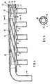
- FIG. 1 denotes an evaporator, which essentially consists of an evaporator block comprising a plurality of tubes 2 and ribs 3 arranged transversely thereto.
- the tubes 2 of a row are each connected to the tubes 2 of a next row by means of deflection bends 4, so that the pipes connected to one another form a pipe string from the first to the last row of pipes
- a distribution pipe 5 to which the pipes 2 of the first pipe row are connected is arranged above the pipe ends of the first pipe row, the distribution pipe 5 is closed at one end and the other The end is connected to an expansion valve 7 via a feed pipe 6.
- FIG. 2 shows a section through a distribution pipe 5, to which the pipes 2 of the evaporator are connected.
- the distribution pipe 5 is closed at one end by means of a plate 9 which is shaped in such a way that it has in its center a cone 11 directed into the distribution pipe 5 and around it an outward annular recess 10.
- a pipe body 12 is arranged centrally in the distribution pipe 5 and has a sculpted end 13 on the side to which the supply pipe 6 is connected, into which the supply pipe 6 projects.
- the tubular body 12 extends evenly up to just before the plate 9 and is supported at this end by a few radially outwardly directed tabs 14 on the inner wall of the distribution tube 5. Between Tabs 14 have openings through which the refrigerant can pass.
- the tubular body 12 thus forms a calming section 15, which extends over the entire length from the end 13 which is topped up to the end adjacent to the plate 9. Between the tube body 12 and the tube 5 there is an annular space 16 from which the evaporator tubes 2 originate.
- the refrigerant supplied through the feed pipe 6 is passed through the calming section 15 and deflected on the plate 9 into the annular space 16 and divided into the annular space 16 acting as a distribution space between the parallel evaporator tubes 2.
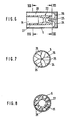
- FIG. 3 shows an embodiment variant of the end of the distribution pipe 5 shown on the right in FIG.
- the tubular body 12 forming the calming section 15 extends to and is attached to a plate 17 which closes the distribution tube 5 and is essentially flat.
- the angled tabs 14 according to FIG. 2 are not required to support the tubular body 12.
- several openings 18 are provided near the plate 17 in the tubular body 12, which are evenly distributed over the circumference of the tubular body 12.
- FIG. 4 shows a section through a distribution pipe 5, in which a tubular body 19 is arranged, which on its lateral surface 5 has radial ribs 20, which run helically along the lateral surface of the tubular body 19.
- the ribs 20 project up to the wall of the distribution pipe 5 and thus form between the tubular body 19 and the distribution pipe 5 a number of coiled channels corresponding to the number of the ribs 20
- a fluid distributor 22 which is designed in the manner of a Venturi nozzle and consists of two parts 23 and 25.
- 23 denotes a sleeve pressed into the tubular body 19, which, viewed in the direction of flow, initially has a taper and then a conical widening.
- a cone designated 25 projects into this conical enlargement and is a component of a disk 24 closing the distribution tube 5.
- deflection channels 26 are provided in the disk, which overlap the end of the tubular body 19 and thus deflect the refrigerant from the flow distributor 22 into the channels 21.
- Figure 5 shows a section along the line VV in Figure 4. From this illustration it can be seen that within the distribution tube 5, the tubular body 19 is arranged with five radial ribs 2o, the ribs 2o made in one piece with the tubular body 19 on the wall of the Distributor tube 5 abut. A channel 21 is formed between two ribs 2o.
- FIG. 6 shows an embodiment variant of FIG. 4, in which the distribution pipe 5 is likewise closed by a disk 24 with a central cone 25 and deflection channels 26.
- the distribution tube 5 there is a cylindrical body 27, which is preferably made of plastic and which ends near the disc 24.
- the deflection channels 26 overlap the end of the body 27, which at the end of the calming section 15 has a cone tapering the flow cross section and then an expanding cone.
- the aforementioned cone 25 projects into the expanding cone the disc 24 and thus forms the fluid distributor; 22.
- a plurality of axially extending channels 28 are arranged on the lateral surface of the cylindrical body 27 and lead to the connections of the evaporator tubes 2.
- FIG. 7 shows a section along the line VII-VII in FIG. 6.
- the disk 24 closing the distribution tube is inserted, in the middle of which the tip of the cone 25 is present.
- the disk 24 has five deflection channels 26 arranged in a star shape.
- FIG. 8 shows a section along the line VIII-VIII in FIG. 6. From this illustration it can be seen that a cylindrical body 27 is arranged in the distribution tube 5, in the middle of which a calming section 15 forms a central bore. Five channels 28, which are covered by the distribution tube 5, are arranged on the circumferential surface of the cylindrical body 27 and are distributed uniformly over the circumference.
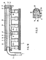
- FIG. 9 shows the end of the distribution pipe 5 which is remote from the feed pipe 6 and in which a cylindrical body 29 with a central bore is inserted as a calming section 15.
- the body 29 On the lateral surface, the body 29 has a plurality of helically extending channels 3o, which are formed between ribs 31 of the body 29 and are covered by the distribution pipe 5. 3o The channels each leading into the region of a terminal of Verdam p ferrohre 2.
- the manifold 5 has a spherically formed end of the pipe 32. The end of the body 29 is at a distance from this spherical end 32, so that an unimpeded passage of the refrigerant from the calming section into the distribution channels 3o is possible.
- FIG. 10 shows the entire longitudinal section through a distributor plug 5 with a body 33 located therein, which has a central bore 34 which extends over the entire length of the body 33 and serves as a calming section 15 for the refrigerant.
- 6 to the state shown in the end shown on the left 1 0 of the body 33 opens the supply pipe into the bore 34 to the manifold six pipe stub 35 are arranged at a uniform distance to which the transversely extending through fins 3 evaporator tubes 2 are connected.
- the end of the distribution pipe 5 which is remote from the feed pipe 6 is closed by a disk 36 which is provided on its outer circumferential surface with a sealing ring 37.
- each channel 39 extending in the longitudinal direction of the body are distributed over a circumference, but at a radial distance from the bore 34 and the lateral surface 38 of the body 33.
- each of the channels formed by the portions 39, 4o, 41 opens at one of which is arranged on an axis parallel of the manifold 5 connecting piece 35th
- a cone 42 is arranged which protrudes a little into the central bore 34 and whose outer surface merges into deflection channels 43, the outer ends of which are congruent with the channels 39 in the body 33.
- the refrigerant is thus led from the expansion valve through the feed pipe 6 into the calming section 15. Due to the The radii of curvature of the feed pipe 6 are narrow, so that the wet steam mixture segregates, so that the refrigerant is at least partially in two phases. In the calming section 15, a uniform distribution of the mass flow over the cross section of the calming section 15 is then achieved, so that the refrigerant is also divided into the individual tube strings of the evaporator into individual streams with the same mass.
Landscapes
- Engineering & Computer Science (AREA)
- Physics & Mathematics (AREA)
- Mechanical Engineering (AREA)
- Thermal Sciences (AREA)
- General Engineering & Computer Science (AREA)
- Heat-Exchange Devices With Radiators And Conduit Assemblies (AREA)
- Air-Conditioning For Vehicles (AREA)
Applications Claiming Priority (2)
| Application Number | Priority Date | Filing Date | Title |
|---|---|---|---|
| DE19843413931 DE3413931A1 (de) | 1984-04-13 | 1984-04-13 | Verdampfer, insbesondere fuer klimaanlagen in kraftfahrzeugen |
| DE3413931 | 1984-04-13 |
Publications (3)
| Publication Number | Publication Date |
|---|---|
| EP0158081A2 true EP0158081A2 (fr) | 1985-10-16 |
| EP0158081A3 EP0158081A3 (en) | 1985-12-27 |
| EP0158081B1 EP0158081B1 (fr) | 1988-01-07 |
Family
ID=6233466
Family Applications (1)
| Application Number | Title | Priority Date | Filing Date |
|---|---|---|---|
| EP85102080A Expired EP0158081B1 (fr) | 1984-04-13 | 1985-02-26 | Evaporateur, en particulier pour des installations de conditionnement d'air de véhicules automobiles |
Country Status (4)
| Country | Link |
|---|---|
| US (1) | US4593539A (fr) |
| EP (1) | EP0158081B1 (fr) |
| DE (2) | DE3413931A1 (fr) |
| ES (1) | ES295721Y (fr) |
Cited By (4)
| Publication number | Priority date | Publication date | Assignee | Title |
|---|---|---|---|---|
| EP0634615A1 (fr) * | 1991-04-24 | 1995-01-18 | Modine Manufacturing Company | Evaporateur pour un réfrigérant |
| EP1483539A4 (fr) * | 2002-02-28 | 2012-09-05 | Evaporateur et cycle de refrigeration | |
| WO2014127964A1 (fr) * | 2013-02-20 | 2014-08-28 | Behr Gmbh & Co. Kg | Élément de transfert thermique |
| WO2014143951A3 (fr) * | 2013-03-15 | 2015-01-08 | Parker-Hannifin Corporation | Distributeur de réfrigérant |
Families Citing this family (41)
| Publication number | Priority date | Publication date | Assignee | Title |
|---|---|---|---|---|
| US5243838A (en) * | 1989-08-18 | 1993-09-14 | Matsushita Refrigeration Company | Refrigerant shunt |
| US4922732A (en) * | 1989-11-20 | 1990-05-08 | Dyna-Manufacturing, Ltd. | Evaporator system for refrigeration systems |
| AT396834B (de) * | 1992-05-04 | 1993-12-27 | Friedmann Kg Alex | Kältemaschine |
| DE9302504U1 (de) * | 1993-02-20 | 1993-05-13 | Behr GmbH & Co, 7000 Stuttgart | Kältemittelverteiler für einen Verdampfer |
| ATE163224T1 (de) * | 1993-07-03 | 1998-02-15 | Flitsch E Gmbh & Co | Plattenwärmeaustauscher mit kältemittelverteiler |
| DE9401680U1 (de) * | 1994-02-02 | 1994-03-24 | Behr Gmbh & Co, 70469 Stuttgart | Kältemittel-Verdampfer für eine Klimaanlage, insbesondere für Kraftfahrzeuge |
| US5479784A (en) * | 1994-05-09 | 1996-01-02 | Carrier Corporation | Refrigerant distribution device |
| MXPA96004485A (es) * | 1995-10-02 | 2008-10-22 | Calsonic Corp | Unidad de valvula evaporadora de expansion para utilizarse en un sistema de aire acondicionado de un automovil. |
| US5842351A (en) * | 1997-10-24 | 1998-12-01 | American Standard Inc. | Mixing device for improved distribution of refrigerant to evaporator |
| US6179051B1 (en) | 1997-12-24 | 2001-01-30 | Delaware Capital Formation, Inc. | Distributor for plate heat exchangers |
| WO2000011383A1 (fr) | 1998-08-25 | 2000-03-02 | Aeroquip Corporation | Ensemble collecteur |
| US7377126B2 (en) | 2004-07-14 | 2008-05-27 | Carrier Corporation | Refrigeration system |
| US20060101850A1 (en) * | 2004-11-12 | 2006-05-18 | Carrier Corporation | Parallel flow evaporator with shaped manifolds |
| US7398819B2 (en) * | 2004-11-12 | 2008-07-15 | Carrier Corporation | Minichannel heat exchanger with restrictive inserts |
| US7806171B2 (en) * | 2004-11-12 | 2010-10-05 | Carrier Corporation | Parallel flow evaporator with spiral inlet manifold |
| US20060137368A1 (en) * | 2004-12-27 | 2006-06-29 | Carrier Corporation | Visual display of temperature differences for refrigerant charge indication |
| CN101111731A (zh) * | 2005-02-02 | 2008-01-23 | 开利公司 | 用于微流道热交换器的液体-蒸气分离器 |
| MX2007009246A (es) * | 2005-02-02 | 2007-09-04 | Carrier Corp | Insercion de tubo y disposicion de doble flujo para un colector de una bomba de calor. |
| US7967060B2 (en) * | 2005-08-18 | 2011-06-28 | Parker-Hannifin Corporation | Evaporating heat exchanger |
| CN101384868A (zh) * | 2006-02-15 | 2009-03-11 | Gac株式会社 | 热交换器 |
| US8240367B2 (en) * | 2007-06-28 | 2012-08-14 | Exxonmobil Research And Engineering Company | Plate heat exchanger port insert and method for alleviating vibrations in a heat exchanger |
| US7921558B2 (en) * | 2008-01-09 | 2011-04-12 | Delphi Technologies, Inc. | Non-cylindrical refrigerant conduit and method of making same |
| US20090173482A1 (en) * | 2008-01-09 | 2009-07-09 | Beamer Henry E | Distributor tube subassembly |
| DE102008014155A1 (de) * | 2008-03-14 | 2009-09-17 | Magna Steyr Fahrzeugtechnik Ag & Co. Kg | Modulares Batteriesystem mit Kühlsystem |
| US20120222847A1 (en) * | 2011-03-01 | 2012-09-06 | Marine Technique Mediterrannee | Heat exchangers the core of which is produced from a three-dimensional hollow laminated panel |
| US9581397B2 (en) | 2011-12-29 | 2017-02-28 | Mahle International Gmbh | Heat exchanger assembly having a distributor tube retainer tab |
| USD735307S1 (en) * | 2012-12-26 | 2015-07-28 | Pgi International Ltd. | Multiport manifold for evaporator coils |
| JP6213004B2 (ja) * | 2013-07-18 | 2017-10-18 | 株式会社デンソー | 冷媒蒸発器 |
| CN105190201B (zh) * | 2013-05-10 | 2017-07-04 | 株式会社电装 | 制冷剂蒸发器 |
| JP6131705B2 (ja) * | 2013-05-10 | 2017-05-24 | 株式会社デンソー | 冷媒蒸発器 |
| JP6123484B2 (ja) * | 2013-05-24 | 2017-05-10 | 株式会社デンソー | 冷媒蒸発器 |
| DE102014007853B3 (de) * | 2014-05-30 | 2015-10-22 | Bernhard Harter | Verfahren und Vorrichtung zum Temperieren eines Wärmeaustauschers |
| US10551099B2 (en) | 2016-02-04 | 2020-02-04 | Mahle International Gmbh | Micro-channel evaporator having compartmentalized distribution |
| TWI645153B (zh) * | 2018-04-26 | 2018-12-21 | 泰碩電子股份有限公司 | 同管分為汽流通道與液流通道的迴路熱管 |
| US10982870B2 (en) * | 2018-08-31 | 2021-04-20 | Jonhson Controls Technology Company | Working fluid distribution systems |
| DE102019002738A1 (de) * | 2019-04-15 | 2020-10-15 | Uhrig Energie Gmbh | Wärmetauschermodul, Wärmetauschersystem und Verfahren zum Herstellen des Wärmetauschersystems |
| WO2021025151A1 (fr) * | 2019-08-08 | 2021-02-11 | 株式会社デンソー | Échangeur de chaleur |
| EP3855059B1 (fr) * | 2020-01-24 | 2023-11-15 | Aptiv Technologies Limited | Diviseur d'écoulement passif et système de refroidissement de liquide le comprenant |
| CN112937248A (zh) * | 2021-03-18 | 2021-06-11 | 奇瑞汽车股份有限公司 | 汽车空调同轴管的制作方法及汽车空调同轴管 |
| EP4517247A1 (fr) * | 2023-08-31 | 2025-03-05 | Carrier Corporation | Distributeur de fluide pour échangeur de chaleur à microcanaux |
| US20250230995A1 (en) * | 2024-01-17 | 2025-07-17 | Carrier Corporation | Fluid distributor for a heat exchanger |
Family Cites Families (19)
| Publication number | Priority date | Publication date | Assignee | Title |
|---|---|---|---|---|
| US1684083A (en) * | 1927-06-02 | 1928-09-11 | Samuel C Bloom | Refrigerating coil |
| US1883057A (en) * | 1928-10-19 | 1932-10-18 | Vilter Mfg Co | Refrigeration unit |
| US2013521A (en) * | 1934-03-14 | 1935-09-03 | Kelvinator Corp | Refrigerating apparatus |
| US2044455A (en) * | 1935-05-16 | 1936-06-16 | Young Radiator Co | Distributing head for evaporators |
| US2063380A (en) * | 1935-10-18 | 1936-12-08 | Peerless Ice Machine Company | Refrigerant distributor |
| US2099186A (en) * | 1935-12-24 | 1937-11-16 | Reuben H Anderegg | Evaporator coil |
| US2220595A (en) * | 1938-11-17 | 1940-11-05 | Young Radiator Co | Distributor head for evaporators |
| GB533858A (en) * | 1939-12-05 | 1941-02-21 | Superheater Co Ltd | Improvements in or relating to heat exchange or other apparatus comprising parallel paths for the flow of fluid |
| DE733340C (de) * | 1940-09-15 | 1943-03-24 | Bbc Brown Boveri & Cie | Kaeltemittelverteiler fuer Trockenverdampfer |
| US2555055A (en) * | 1948-05-14 | 1951-05-29 | Carrier Corp | Refrigerant distributor |
| GB686406A (en) * | 1949-04-15 | 1953-01-21 | Standard Rrfrigeration Company | Pressure reducing or flow restricting device for refrigerating apparatus |
| DE1816731U (de) * | 1960-06-02 | 1960-08-18 | Rudolf Schmitz | Verdampferrohre fuer kuehlanlagen. |
| US3209820A (en) * | 1962-05-28 | 1965-10-05 | Dole Refrigerating Co | Multi-circuit plate and header assembly |
| FR1431920A (fr) * | 1965-02-06 | 1966-03-18 | Ferodo Sa | Perfectionnements aux échangeurs de chaleur |
| DE1501048A1 (de) * | 1965-03-18 | 1969-07-24 | Linde Ag | Einrichtung zur Dampftrocknung bei Einrichtung zur Dampftrocknung bei Verdampfern,insbesondere von Kaelteanlagen |
| US3563055A (en) * | 1969-03-17 | 1971-02-16 | Sporlan Valve Co | Refrrigerant distribvtor |
| JPS53138564A (en) * | 1977-05-10 | 1978-12-04 | Hitachi Ltd | Multitubular type evaporator of air conditioner |
| DE3136374C2 (de) * | 1981-09-14 | 1985-05-09 | Süddeutsche Kühlerfabrik Julius Fr. Behr GmbH & Co KG, 7000 Stuttgart | Kältemittelverdampfer, insbesondere für Klimaanlagen in Kraftfahrzeugen |
| DE3311579C2 (de) * | 1983-03-30 | 1985-10-03 | Süddeutsche Kühlerfabrik Julius Fr. Behr GmbH & Co. KG, 7000 Stuttgart | Wärmetauscher |
-
1984
- 1984-04-13 DE DE19843413931 patent/DE3413931A1/de not_active Ceased
-
1985
- 1985-02-26 EP EP85102080A patent/EP0158081B1/fr not_active Expired
- 1985-02-26 DE DE8585102080T patent/DE3561358D1/de not_active Expired
- 1985-03-08 ES ES1985295721U patent/ES295721Y/es not_active Expired
- 1985-04-03 US US06/719,462 patent/US4593539A/en not_active Expired - Fee Related
Cited By (4)
| Publication number | Priority date | Publication date | Assignee | Title |
|---|---|---|---|---|
| EP0634615A1 (fr) * | 1991-04-24 | 1995-01-18 | Modine Manufacturing Company | Evaporateur pour un réfrigérant |
| EP1483539A4 (fr) * | 2002-02-28 | 2012-09-05 | Evaporateur et cycle de refrigeration | |
| WO2014127964A1 (fr) * | 2013-02-20 | 2014-08-28 | Behr Gmbh & Co. Kg | Élément de transfert thermique |
| WO2014143951A3 (fr) * | 2013-03-15 | 2015-01-08 | Parker-Hannifin Corporation | Distributeur de réfrigérant |
Also Published As
| Publication number | Publication date |
|---|---|
| ES295721U (es) | 1987-04-01 |
| ES295721Y (es) | 1987-11-16 |
| DE3561358D1 (en) | 1988-02-11 |
| EP0158081B1 (fr) | 1988-01-07 |
| US4593539A (en) | 1986-06-10 |
| DE3413931A1 (de) | 1985-10-24 |
| EP0158081A3 (en) | 1985-12-27 |
Similar Documents
| Publication | Publication Date | Title |
|---|---|---|
| EP0158081A2 (fr) | Evaporateur, en particulier pour des installations de conditionnement d'air de véhicules automobiles | |
| EP0121079B1 (fr) | Echangeur de chaleur | |
| EP0132620B1 (fr) | Evaporateur | |
| DE3536315C2 (fr) | ||
| EP0311756B1 (fr) | Support de bec de remplissage pour un réservoir de carburant de véhicule automobile | |
| DE69809652T2 (de) | Verteiler für Röhrenwärmetauscher einer Zweiphasenkältemittel-Kühlanlage | |
| WO2013087310A1 (fr) | Gicleur de carburant pour deux carburants | |
| DE2404039A1 (de) | Verbesserte brennstoffinjektionseinrichtung | |
| EP3084163B1 (fr) | Agencement de tube mélangeur comportant un boîtier | |
| DE2725119B1 (de) | Separatorvorrichtung fuer Eindampfanlagen | |
| EP0890735B2 (fr) | Soupape d'injection de combustible | |
| DE3505196C2 (de) | Wärmetauscher, insbesondere für Kraftfahrzeuge | |
| EP1931872A1 (fr) | Vanne pour reguler un fluide | |
| EP0308855A2 (fr) | Buse d'injection de combustible | |
| DE2443206A1 (de) | Regelbare drossel fuer gase und daempfe | |
| EP3788307B1 (fr) | Dispositif de distribution d'air | |
| DE9302504U1 (de) | Kältemittelverteiler für einen Verdampfer | |
| DE4230092C2 (de) | Wärmetauscher, insbesondere Verdampfer für Klimaanlagen von Kraftfahrzeugen | |
| DE19916674C2 (de) | Akkumulator für eine nach dem "Orifice"-Prinzip arbeitende Klimaanlage, insbesondere Fahrzeugklimaanlage | |
| DE3114386C2 (de) | Brennstoffeinspritzventil für Dieselbremskraftmaschinen | |
| DE9006649U1 (de) | Verdampfer | |
| AT392829B (de) | Anschlusseinrichtung fuer das anschliessen von heizkoerpern | |
| DE3136374A1 (de) | Verdampfer, insbesondere fuer klimaanlagen in kraftfahrzeugen | |
| DE19541908B4 (de) | Befüllungseinrichtung für Luftreifen | |
| DE19735571C2 (de) | Spinneinrichtung zum Ausspinnen von Filamenten aus synthetischen Polymeren |
Legal Events
| Date | Code | Title | Description |
|---|---|---|---|
| PUAI | Public reference made under article 153(3) epc to a published international application that has entered the european phase |
Free format text: ORIGINAL CODE: 0009012 |
|
| AK | Designated contracting states |
Designated state(s): DE FR GB IT SE |
|
| PUAL | Search report despatched |
Free format text: ORIGINAL CODE: 0009013 |
|
| AK | Designated contracting states |
Designated state(s): DE FR GB IT SE |
|
| 17P | Request for examination filed |
Effective date: 19860118 |
|
| 17Q | First examination report despatched |
Effective date: 19860626 |
|
| GRAA | (expected) grant |
Free format text: ORIGINAL CODE: 0009210 |
|
| ITF | It: translation for a ep patent filed | ||
| AK | Designated contracting states |
Kind code of ref document: B1 Designated state(s): DE FR GB IT SE |
|
| GBT | Gb: translation of ep patent filed (gb section 77(6)(a)/1977) | ||
| REF | Corresponds to: |
Ref document number: 3561358 Country of ref document: DE Date of ref document: 19880211 |
|
| ET | Fr: translation filed | ||
| PLBE | No opposition filed within time limit |
Free format text: ORIGINAL CODE: 0009261 |
|
| STAA | Information on the status of an ep patent application or granted ep patent |
Free format text: STATUS: NO OPPOSITION FILED WITHIN TIME LIMIT |
|
| 26N | No opposition filed | ||
| ITTA | It: last paid annual fee | ||
| PGFP | Annual fee paid to national office [announced via postgrant information from national office to epo] |
Ref country code: SE Payment date: 19920108 Year of fee payment: 8 |
|
| PGFP | Annual fee paid to national office [announced via postgrant information from national office to epo] |
Ref country code: GB Payment date: 19921222 Year of fee payment: 9 |
|
| PGFP | Annual fee paid to national office [announced via postgrant information from national office to epo] |
Ref country code: FR Payment date: 19921230 Year of fee payment: 9 |
|
| PGFP | Annual fee paid to national office [announced via postgrant information from national office to epo] |
Ref country code: DE Payment date: 19930204 Year of fee payment: 9 |
|
| PG25 | Lapsed in a contracting state [announced via postgrant information from national office to epo] |
Ref country code: SE Effective date: 19930227 |
|
| PG25 | Lapsed in a contracting state [announced via postgrant information from national office to epo] |
Ref country code: GB Effective date: 19940226 |
|
| GBPC | Gb: european patent ceased through non-payment of renewal fee |
Effective date: 19940226 |
|
| PG25 | Lapsed in a contracting state [announced via postgrant information from national office to epo] |
Ref country code: FR Effective date: 19941031 |
|
| PG25 | Lapsed in a contracting state [announced via postgrant information from national office to epo] |
Ref country code: DE Effective date: 19941101 |
|
| REG | Reference to a national code |
Ref country code: FR Ref legal event code: ST |
|
| EUG | Se: european patent has lapsed |
Ref document number: 85102080.0 Effective date: 19930912 |