EP0158097B1 - Vorrichtung zum Versprühen von Schmelzkleber - Google Patents
Vorrichtung zum Versprühen von Schmelzkleber Download PDFInfo
- Publication number
- EP0158097B1 EP0158097B1 EP85102288A EP85102288A EP0158097B1 EP 0158097 B1 EP0158097 B1 EP 0158097B1 EP 85102288 A EP85102288 A EP 85102288A EP 85102288 A EP85102288 A EP 85102288A EP 0158097 B1 EP0158097 B1 EP 0158097B1
- Authority
- EP
- European Patent Office
- Prior art keywords
- gun body
- spraying
- gun
- air
- hot
- Prior art date
- Legal status (The legal status is an assumption and is not a legal conclusion. Google has not performed a legal analysis and makes no representation as to the accuracy of the status listed.)
- Expired
Links
- 238000005507 spraying Methods 0.000 title claims abstract description 12
- 239000003292 glue Substances 0.000 title claims abstract 7
- 239000012943 hotmelt Substances 0.000 claims abstract 5
- 238000010438 heat treatment Methods 0.000 abstract description 16
- 238000001125 extrusion Methods 0.000 abstract 2
- 238000000034 method Methods 0.000 abstract 1
- 239000007921 spray Substances 0.000 description 16
- 239000004831 Hot glue Substances 0.000 description 15
- 239000002184 metal Substances 0.000 description 7
- 239000000853 adhesive Substances 0.000 description 4
- 230000001070 adhesive effect Effects 0.000 description 4
- 238000010276 construction Methods 0.000 description 1
- 230000008878 coupling Effects 0.000 description 1
- 238000010168 coupling process Methods 0.000 description 1
- 238000005859 coupling reaction Methods 0.000 description 1
- 238000006073 displacement reaction Methods 0.000 description 1
- 238000002347 injection Methods 0.000 description 1
- 239000007924 injection Substances 0.000 description 1
- 238000012423 maintenance Methods 0.000 description 1
- 239000000463 material Substances 0.000 description 1
- 125000006850 spacer group Chemical group 0.000 description 1
Images

Classifications
-
- B—PERFORMING OPERATIONS; TRANSPORTING
- B05—SPRAYING OR ATOMISING IN GENERAL; APPLYING FLUENT MATERIALS TO SURFACES, IN GENERAL
- B05B—SPRAYING APPARATUS; ATOMISING APPARATUS; NOZZLES
- B05B7/00—Spraying apparatus for discharge of liquids or other fluent materials from two or more sources, e.g. of liquid and air, of powder and gas
- B05B7/16—Spraying apparatus for discharge of liquids or other fluent materials from two or more sources, e.g. of liquid and air, of powder and gas incorporating means for heating or cooling the material to be sprayed
- B05B7/1606—Spraying apparatus for discharge of liquids or other fluent materials from two or more sources, e.g. of liquid and air, of powder and gas incorporating means for heating or cooling the material to be sprayed the spraying of the material involving the use of an atomising fluid, e.g. air
- B05B7/1613—Spraying apparatus for discharge of liquids or other fluent materials from two or more sources, e.g. of liquid and air, of powder and gas incorporating means for heating or cooling the material to be sprayed the spraying of the material involving the use of an atomising fluid, e.g. air comprising means for heating the atomising fluid before mixing with the material to be sprayed
Definitions
- the invention relates to a device for spraying hot-melt adhesive comprising a pneumatically operated spray gun with a gun body, via which the hot-melt adhesive can be fed to a valve body having a nozzle, from which the heated air for spraying the hot-melt adhesive can be fed under pressure and along a Heat source is guided.
- DE-A-32 25 844 describes a spray device for hotmelt adhesives, the adhesive being passed through a centrally arranged tube, the outlet of which forms a nozzle.
- the channel is surrounded by a tubular housing, leaving an empty space, in which an electrical heater spirally surrounding the tube is arranged.
- the cavity is connected on one side to the supply line for heated compressed air, which is discharged via a nozzle head surrounding the nozzle.
- the arrangement of the electrical heating around the pipe carrying the hot melt adhesive can result in the disadvantage that the hot melt adhesive is heated to an undesirable extent if the air was not preheated to the required extent.
- the invention is based on the object to design a device of the type described above so that it is ensured that the air required for spraying has the required temperature without the risk that the hot melt adhesive itself is heated too much.
- the device should be of simple construction and thus be low-maintenance.
- the gun body is assigned the heat source arranged in a housing in the form of a heating cartridge, which is helically surrounded by a line carrying the air, with a heat-conducting connection between the housing and the gun body.
- the distance between the housing and the gun body can preferably be changed depending on the hot melt adhesive to be sprayed. This has the advantage that the heating power of the heat source designed as a heating cartridge does not have to be changed.
- the heating cartridge itself is enclosed by a hollow cylindrical element, preferably in the form of a metal sleeve, which has a screw-like depression in its surface, such as a groove, in order to at least partially embed the line therein.
- the device itself can be manually operated, the gun body and the housing receiving the heat source being surrounded by a gun housing which has a handle.
- a 3-way valve is actuated by the latter in order to use this compressed air to allocate both the spray gun and the line surrounding the heat source.
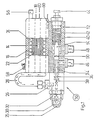
- 1 and 2 each show a device for spraying a hot melt adhesive onto an object to be bonded.
- 1 is an automatic spray gun 10 which has an injection body 12.
- a heat-conducting connection between the housing 16 and the gun body 12 takes place to an adjustable extent.
- a line is arranged on the surface of the metal sleeve 22 in a helical shape, which line can optionally be partially embedded in the metal sleeve 22 (see FIG. 3).
- valve body 26 having a nozzle 25.
- the front end 28 of the line helically surrounding the heating cartridge 14 opens into the valve body 26.
- the nozzle 25 is arranged in the front end of an air head 30, which is connected by means of a coupling ring 32 is connected to the valve housing 26.
- valve needle 36 for opening or closing an opening 38 is slidably arranged.
- the valve needle 36 starts from a piston 40, one end face of which is pressurized with compressed air can be struck so as to cause displacement of the piston 40 and thus the valve needle 36 from the opening 38 against a force caused by a piston spring 42.
- the stroke of the piston can be adjusted by means of a stop screw 44.
- the melted pressure-sensitive hot-melt adhesive is supplied via the connection 46 and the compressed air is charged via the opening 48 for displacing the piston 40.
- the areas of the interior of the gun body which are charged with hot-melt adhesive or compressed air are separated by a section of the piston rod 54 having a seal 50, from which the valve needle 36 goes out.
- the compressed air passed through line 24 and thereby heated is connected via a connection 56 to a compressed air source.
- the adhesive is sprayed in a rotating jet. This is achieved in that the hot melt adhesive is guided coaxially in the air head 30.
- the spray air is swirled in the manner of a rotating jet at the exit point of the hot-melt adhesive via preferably five longitudinal grooves running in the nozzle 25, which ensures that the spraying takes place to the desired extent.
- the longitudinal grooves can describe an angle of approximately 15 ° to the longitudinal axis of the nozzle 25.
- the temperature of the housing 16 is determined via heat sensors 58 and 60, for example, in order to obtain conclusions about the temperature of the air when leaving the helically laid line 24 or in the area of the connection to the gun body 12.
- the structure with regard to the gun body and the housing receiving the heat source is the same in the hand-held spray gun shown in FIG. 2, so that the same elements are provided with the same reference numerals.
- the embodiments differ, however, in that the gun body 12 and the housing 16 are surrounded by a common housing 62 which has a handle 64.
- a 3-way valve 68 to be actuated by an actuating element such as lever 66, via which compressed air, on the one hand, into the gun body 12 (connection 70) and, on the other hand, to the line 24 (connection 76 ) to be led.
- the heated air flowing via the line part 28 is guided within the valve housing 26 in order to heat it also to the extent necessary so that heat is not extracted from the molten adhesive to an inadmissible extent.
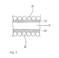
- FIG. 3 shows a section of the line 24 partially embedded in the metal sleeve 22, which together surround the heating cartridge 14. It can be seen that there is good thermal contact over a large area of the circumference of the line 24 with the surface of the metal sleeve 22. thereby ensuring that the air flowing in line 24 is heated to the required extent.
- the metal sleeve 22 can be heated up to 500 ° in the front region.
- the temperature supplied to the valve housing 26 has a temperature of 200-220 ° Celsius at a throughput of 180 to 200 l per minute. This temperature is sufficient for a hot melt adhesive to be sprayed over the nozzle 25 to the required extent.
Landscapes
- Nozzles (AREA)
- Application Of Or Painting With Fluid Materials (AREA)
- Coating Apparatus (AREA)
- Adhesives Or Adhesive Processes (AREA)
- Coating By Spraying Or Casting (AREA)
Description
- Die Erfindung bezieht sich auf eine Vorrichtung zum Versprühen von Schmelzkleber umfassend eine pneumatisch betriebene Spritzpistole mit Pistolenkörper, über den der Schmelzkleber einem von dem Pistolenkörper ausgehenden eine Düse aufweisenden Ventilkörper zuführbar ist, dem zum Versprühen des Schmelzklebers erwärmte Luft unter Druck zuleitbar ist, die entlang einer Wärmequelle geführt ist.
- In der DE-A-32 25 844 ist eine Sprüheinrichtung für Heizschmelzklebstoffe beschrieben, wobei der Klebstoff durch ein zentral angeordnetes Rohr geführt wird, dessen Ausgang eine Düse bildet. Der Kanal ist unter Belassung eines Hohlraumes von einem rohrförmigen Gehäuse umgeben, in dem eine das Rohr spiralförmig umgebende elektrische Heizung angeordnet ist. Der Hohlraum ist an einer Seite mit der Zuführleitung für erhitzte Druckluft verbunden, die über einen die Düse umgebenden Düsenkopf abgegeben wird. Durch die Anordnung der elektrischen Heizung um das den Schmelzkleber führende Rohr kann sich der Nachteil ergeben, daß der Schmelzkleber im unerwünschten Umfang erwärmt wird, wenn die Luft nicht im erforderlichen Umfang vorgeheizt war.
- Werden von einer Druckluftquelle mehrere Spritzautomaten oder Handspritzpistolen versorgt, so sind, um die benötigten Luftmengen im erforderlichen Umfang zu erwärmen, aufwendige Heizvorrichtungen erforderlich, die zusätzlich zu den Heizquellen benötigt werden, durch die die Spritzkörper der Spritzautomaten bzw. Handspritzpistolen erwärmt werden müssen.
- Der Erfindung liegt zum einen die Aufgabe zugrunde, eine Vorrichtung der zuvor beschriebenen Art so auszubilden, daß sichergestellt ist, daß die für das Versprühen benötigte Luft die erforderliche Temperatur aufweist, ohne daß die Gefahr besteht, daß der Schmelzkleber selbst zu sehr erwärmt wird. Dabei soll die Vorrichtung konstruktiv einfach gebaut und damit wartungsarm sein.
- Die Aufgabe wird erfindungsgemäß dadurch gelöst, daß dem Pistolenkörper die in einem Gehäuse angeordnete Wärmequelle in Form einer Heizpatrone zugeordnet ist, die schraubenförmig von einer die Luft führenden Leitung umgeben ist, wobei zwischen dem Gehäuse und dem Pistolenkörper eine wärmeleitende Verbindung besteht. Dabei ist vorzugsweise zur kontrollierten Erwärmung des Pistolenkörpers in Abhängigkeit von dem zu versprühenden Schmelzkleber der Abstand zwischen dem Gehäuse und dem Pistolenkörper veränderbar. Dadurch ergibt sich der Vorteil, daß die Heizleistung der als Heizpatrone ausgebildeten Wärmequelle nicht verändert werden muß.
- Die Heizpatrone selbst ist von einem vorzugsweise als Metallhülse ausgebildeten hohlzylindrischen Element umschlossen, die in ihrer Oberfläche eine schraubenförmig verlaufende Vertiefung wie Nut aufweist, um in dieser zumindest teilweise die Leitung einzubetten.
- Die Vorrichtung selbst kann handbetätigt sein, wobei der Pistolenkörper und das die Wärmequelle aufnehmende Gehäuse von einem Pistolengehäuse umgeben ist, welches ein Handgriff aufweist. Von diesem wird ein 3-Wege-Ventil betätigt, um über dieses Druckluft sowohl der Spritzpistole als auch der die Wärmequelle umgebenden Leitung zuzuteilen.
- Weitere Einzelheiten, Vorteile und Merkmale der Erfindung ergeben sich aus der nachfolgenden Beschreibung von in der Zeichnung dargestellten Ausführungsbeispielen, durch die jedoch eine Einschränkung des Erfindungsgedanken nicht erfolgen soll.
-
- Fig. 1 eine Schnittdarstellung eines Spritzautomaten,
- Fig. 2 eine Schnittdarstellung einer Handspritzpistole und
- Fig. 3 einen Ausschnitt aus der Fig. 2.
- Den Fig. 1 und 2 ist jeweils eine Vorrichtung zum Versprühen eines Haftschmelzklebers auf einen zu verklebenden Gegenstand dargestellt. Dabei handelt es sich bei der Darstellung in Fig. 1 um einen Spritzautomaten 10 der einen Spritzkörper 12 aufweist. An einer Fläche des Spritzkörpers 12 grenzt ein eine Heizpatrone 14 aufweisendes Gehäuse 16 an. Dabei erfolgt eine wärmeleitende Verbindung zwischen dem Gehäuse 16 und dem Pistolenkörper 12 im einstellbaren Umfang. Vorzugsweise verläuft zentrisch im Gehäuse 16 die über Anschlüsse 18 und 20 mit elektrischer Energie zu versorgende Heizpatrone 14, die ihrerseits von einer Metallhülse 22 umschlossen ist. Auf der Oberfläche der Metallhülse 22 ist schraubenförmig eine Leitung angeordnet, die gegebenenfalls teilweise in der Metallhülse 22 eingebettet sein kann (siehe Fig. 3).
- Am vorderen Ende des Spritzkörpers 12 befindet sich ein eine Düse 25 aufweisender Ventilkörper 26. In dem Ventilkörper 26 mündet das vordere Ende 28 der die Heizpatrone 14 schraubenförmig umgebenden Leitung - Die Düse 25 ist im vorderen Ende eines Luftkopfes 30 angeordnet, der mittels eines Überwurfrings 32 mit dem Ventilgehäuse 26 verbunden ist.
- Im Ventilgehäuse 26 mündet eine axiale Bohrung 34 des Ventilkörpers 12, in der koaxial eine Ventilnadel 36 zum Öffnen bzw. Verschließen einer Öffnung 38 verschiebbar angeordnet ist. Die Ventilnadel 36 geht von einem Kolben 40 aus, dessen eine Stirnfläche von Druckluft beaufschlagbar ist, um so ein Verschieben des Kolbens 40 und damit der Ventilnadel 36 von der Öffnung 38 entgegen einer von einer Kolbenfeder 42 hervorgerufenen Kraft hervorzurufen. Dabei kann der Hub des Kolbens mittels einer Anschlagschraube 44 eingestellt werden.
- Über den Anschluß 46 erfolgt die Zuführung des geschmolzenen Haftschmelzklebers und über die Öffnung 48 die Druckluftbeschickung zum Verschieben des Kolbens 40. Die mit Schmelzkleber bzw. Druckluft beschickten Bereiche des Pistolenkörperinneren sind durch einen eine Dichtung 50 aufweisenden Abschnitt der Kolbenstange 54 getrennt, von der die Ventilnadel 36 ausgeht.
- Erwähntermaßen kann der Abstand zwischen dem Gehäuse 16 und dem Pistolenkörper 12 z. B. durch Distanzscheiben, -ringe oder -plättchen veränderbar eingestellt werden, um so den Wärmeübergang und damit die Erwärmung des Pistolenkörpers 12 im gewünschten Umfang beeinflussen zu können.
- Die durch die Leitung 24 geführte und dabei erwärmte Druckluft wird über einen Anschluß 56 mit einer Druckluftquelle verbunden. Das Versprühen des Klebers erfolgt im Drehstrahl. Dies wird dadurch erzielt, daß koaxial im Luftkopf 30 der Schmelzkleber geführt wird. Über vorzugsweise fünf in Düse 25 verlaufende Längsnuten erfolgt eine Verwirbelung der Sprühluft in Art eines Drehstrahis im Austrittspunkt des Schmelzklebers, wodurch sichergestellt ist, daß das Aufsprühen im gewünschten Umfang erfolgt. Dabei können die Längsnuten einen Winkel von ca. 15° zur Längsachse der Düse 25 beschreiben.
- Über beispielhaft dargestellte Wärmefühler 58 bzw. 60 wird die Temperatur des Gehäuses 16 bestimmt, um so Rückschlüsse auf die Temperatur der Luft beim Verlassen der schraubenförmig verlegten Leitung 24 bzw. im Bereich der Verbindung zu dem Pistolenkörper 12 zu erhalten.
- Der Aufbau bezüglich des Pistolenkörpers und des Wärmequelle aufnehmenden Gehäuses ist bei der der Fig. 2 zu entnehmenden Handspritzpistole gleich, so daß gleiche Elemente mit gleichen Bezugszeichen versehen sind.
- Die Ausführungsformen unterscheiden sich jedoch darin, daß der Pistolenkörper 12 und das Gehäuse 16 von einem gemeinsamen Gehäuse 62 umgeben sind, das einen Handgriff 64 aufweist. In dem Handgriff befindet sich ein von einem Betätigungsorgan wie Hebel 66 zu betätigendes 3-Wege-Ventil 68, über das Druckluft zum einen in den Pistolenkörper 12 (Verbindung 70) und zum anderen zu der schraubenförmig um die Heizpatrone 14 gelegte Leitung 24 (Verbindung 76) geführt wird.
- Der Fig. 2 ist desweiteren zu entnehmen, daß der erwärmte und geschmolzene Kleber über einen vorzugsweise beheizten Materialschlauch 72 geführt wird.
- Auch sei nachdrücklich darauf hingewiesen, daß die über den Leitungsteil 28 strömende erwärmte Luft innerhalb des Ventilgehäuses 26 geführt wird, um dieses ebenfalls im erforderlichen Umfang zu erwärmen, damit dem geschmolzenem Kleber selbst nicht im unzulässigen Umfang Wärme entzogen wird.
- In Fig. 3 ist ein Ausschnitt der in der Metallhülse 22 teilweise eingebetteten Leitung 24 dargestellt, die gemeinsam die Heizpatrone 14 umgeben. Man erkennt, daß ein guter Wärmekontakt über einen großen Bereich des Umfangs der Leitung 24 mit der Oberfläche der Metallhülse 22 erfolgt. wodurch sichergestellt ist, daß die in der Leitung 24 strömende Luft im erforderlichen Umfang erwärmt wird.
- Mit einer Heizpatrone einer Leistung von 350 Watt kann eine Erwärmung der Metallhülse 22 im vorderen Bereich bis zu 500° erfolgen. In diesem Fall weist die dem Ventilgehäuse 26 zugeführte Temperatur bei einem Durchsatz von 180 bis 200 I pro Minute eine Temperatur von 200-220° Celsius auf. Diese Temperatur reicht aus, daß ein Schmelzkleber über die Düse 25 im erforderlichen Umfang versprüht wird.
- Bei höheren Drücken kann durch Erhöhung der Leistung der Heizpatrone 14 auf z. B. 560 Watt eine Lufterwärmung von 300° Celsius im Bereich der Leitung 28 erreicht werden. Wird nun die Luft mit einem Druck von z. B. 4-4,5 bar abgegeben, so genügt die vorher eingestellte Temperatur trotz der plötzlichen Temperaturniedrigung am Düsenaustritt aus, um Schmelzkleber noch im erforderlichen Umfang versprühen zu können.
Claims (4)
Priority Applications (1)
| Application Number | Priority Date | Filing Date | Title |
|---|---|---|---|
| AT85102288T ATE32667T1 (de) | 1984-03-01 | 1985-03-01 | Vorrichtung zum verspruehen von schmelzkleber. |
Applications Claiming Priority (2)
| Application Number | Priority Date | Filing Date | Title |
|---|---|---|---|
| DE19848406368U DE8406368U1 (de) | 1984-03-01 | 1984-03-01 | Duesenelement |
| DE8406368U | 1984-03-01 |
Publications (2)
| Publication Number | Publication Date |
|---|---|
| EP0158097A1 EP0158097A1 (de) | 1985-10-16 |
| EP0158097B1 true EP0158097B1 (de) | 1988-03-02 |
Family
ID=6764243
Family Applications (1)
| Application Number | Title | Priority Date | Filing Date |
|---|---|---|---|
| EP85102288A Expired EP0158097B1 (de) | 1984-03-01 | 1985-03-01 | Vorrichtung zum Versprühen von Schmelzkleber |
Country Status (4)
| Country | Link |
|---|---|
| US (1) | US4669661A (de) |
| EP (1) | EP0158097B1 (de) |
| AT (1) | ATE32667T1 (de) |
| DE (2) | DE8406368U1 (de) |
Cited By (3)
| Publication number | Priority date | Publication date | Assignee | Title |
|---|---|---|---|---|
| DE19809170A1 (de) * | 1998-02-26 | 1999-09-09 | Metacap Gmbh Fabrikation Farbs | Heißwachs-Sprühvorrichtung |
| DE10034425A1 (de) * | 2000-07-14 | 2002-01-31 | Rudi Schmidhaeuser | Verfahren und Vorrichtung zum Aufbringen eines Trennmittels |
| DE102005029688A1 (de) * | 2005-06-21 | 2007-02-01 | Krautzberger Gmbh | Spritzvorrichtung und Spritzkopf |
Families Citing this family (24)
| Publication number | Priority date | Publication date | Assignee | Title |
|---|---|---|---|---|
| DE3576657D1 (de) * | 1985-12-05 | 1990-04-26 | Nordson Corp | Vorrichtung zum auftragen oder verspruehen viskoser materialien. |
| US5020723A (en) * | 1989-08-10 | 1991-06-04 | Crist Lawrence E | Hot melt glue spraying device |
| GB9108865D0 (en) * | 1991-04-25 | 1991-06-12 | Univ Leeds | Sprayer |
| CH680655A5 (de) * | 1991-11-07 | 1992-10-15 | Ulrich Sigrist | |
| US5292068A (en) * | 1992-08-17 | 1994-03-08 | Nordson Corporation | One-piece, zero cavity nozzle for swirl spray of adhesive |
| US5375766A (en) * | 1993-03-26 | 1994-12-27 | The Dexter Corporation | Hot melt adhesive spray dispenser |
| US5478014A (en) * | 1994-04-20 | 1995-12-26 | Hynds; James E. | Method and system for hot air spray coating and atomizing device for use therein |
| US5526981A (en) * | 1994-10-31 | 1996-06-18 | Sanson; Bruce A. | Adhesive spray system, and methods of constructing and utilizing same |
| USD379577S (en) * | 1995-09-06 | 1997-06-03 | The Esab Group, Inc. | Nozzle for a plasma arc torch |
| US6206963B1 (en) | 1998-08-25 | 2001-03-27 | Philip Morris Incorporated | Nozzle |
| US6202892B1 (en) | 1998-10-15 | 2001-03-20 | Bernard C. Lasko | Control system for glue gun |
| KR100368319B1 (ko) * | 1998-12-30 | 2003-03-17 | 주식회사 하이닉스반도체 | 액체운송장치 |
| US6273661B1 (en) | 2000-08-07 | 2001-08-14 | Hewlett-Packard Company | Method and apparatus for binding print media |
| US20040224086A1 (en) * | 2003-05-05 | 2004-11-11 | Wright Ryan Erin | Automated hot melt application apparatus and method |
| US7221859B2 (en) * | 2004-12-01 | 2007-05-22 | Liquamelt Corp. | Multi-function heat exchanger |
| EP2283931A3 (de) * | 2006-01-06 | 2011-04-13 | Nordson Corporation | Flüssigkeitsspender mit individualisierter Prozessluftsteuerung |
| KR100744694B1 (ko) | 2006-04-19 | 2007-08-01 | 주식회사 카엘 | 이온교환 섬유 복합필터 제조장치 및 제조방법 |
| US20090220686A1 (en) * | 2008-02-29 | 2009-09-03 | Corey Minion | Compressed air spray glue gun |
| TWI565843B (zh) | 2014-06-19 | 2017-01-11 | 財團法人紡織產業綜合研究所 | 噴織裝置與噴織系統 |
| DE102015213421A1 (de) * | 2015-07-16 | 2017-01-19 | IPR-Intelligente Peripherien für Roboter GmbH | Wachssprühpistole und Austragsystem mit einer solchen Wachssprühpistole |
| US10307976B2 (en) | 2016-06-22 | 2019-06-04 | Service King Paint & Body, Llc | Automotive repair systems including three-dimensional (3D) printed attachment parts and methods of use |
| DE102020119763A1 (de) | 2020-07-27 | 2022-01-27 | Focke & Co. (Gmbh & Co. Kg) | Ventilanordnung |
| CN113447206B (zh) * | 2021-08-31 | 2021-11-30 | 常州市翔波机械制造有限公司 | 一种用于阀门生产的密封性检测设备 |
| CN115591741A (zh) * | 2022-08-18 | 2023-01-13 | 苏州福斯特万电子科技有限公司(Cn) | 点胶机用双胶筒切换供料装置 |
Family Cites Families (15)
| Publication number | Priority date | Publication date | Assignee | Title |
|---|---|---|---|---|
| US1609465A (en) * | 1922-04-01 | 1926-12-07 | Spray Painting & Finishing Equ | Tool for applying coating |
| US1644081A (en) * | 1924-05-08 | 1927-10-04 | Preble James Jarvis | Tool or apparatus for applying coating |
| US1792551A (en) * | 1929-11-04 | 1931-02-17 | William S Rice | Metal-spraying apparatus |
| US2266365A (en) * | 1939-03-06 | 1941-12-16 | Binks Mfg Co | Automatically operated spraying system |
| US2362634A (en) * | 1942-08-20 | 1944-11-14 | United Shoe Machinery Corp | Spraying apparatus |
| US2401504A (en) * | 1943-12-04 | 1946-06-04 | Jens A Paasche | Airbrush device |
| US2434911A (en) * | 1944-12-26 | 1948-01-27 | Standard Telephones Cables Ltd | Heating and spraying device |
| FR937178A (fr) * | 1946-12-20 | 1948-08-10 | Dispositif pour la projection à chaud de bitumes, asphaltes, résines, cires et produits analogues | |
| FR1324780A (fr) * | 1962-06-12 | 1963-04-19 | Pistolet chauffant par application aérothermique | |
| US3496668A (en) * | 1968-04-04 | 1970-02-24 | Dittmore Freimuth Corp | Insecticide fogger apparatus |
| US3776462A (en) * | 1973-01-08 | 1973-12-04 | P Payne | Metal spraying apparatus |
| US4056707A (en) * | 1975-10-06 | 1977-11-01 | Farnam Franklin C | Electrical heating device for use with aerosol containers |
| US4260873A (en) * | 1978-10-18 | 1981-04-07 | A-T-O Inc. | Electrically heated hand held vaporizer for vapor polishing plastic surfaces |
| EP0041975B1 (de) * | 1979-12-18 | 1985-03-20 | AMIAUT, Jean | Verbesserte spritzpistole zum warmspritzen von farben |
| DE3225844C2 (de) * | 1982-07-09 | 1985-06-20 | Sprimag Spritzmaschinenbau Gmbh, 7312 Kirchheim | Verfahren und Vorrichtung zum Auftragen von Schichten aus thermoplastischen Kunststoffen |
-
1984
- 1984-03-01 DE DE19848406368U patent/DE8406368U1/de not_active Expired
- 1984-12-10 US US06/679,703 patent/US4669661A/en not_active Expired - Lifetime
-
1985
- 1985-03-01 DE DE8585102288T patent/DE3561688D1/de not_active Expired
- 1985-03-01 AT AT85102288T patent/ATE32667T1/de not_active IP Right Cessation
- 1985-03-01 EP EP85102288A patent/EP0158097B1/de not_active Expired
Cited By (5)
| Publication number | Priority date | Publication date | Assignee | Title |
|---|---|---|---|---|
| DE19809170A1 (de) * | 1998-02-26 | 1999-09-09 | Metacap Gmbh Fabrikation Farbs | Heißwachs-Sprühvorrichtung |
| DE19809170B4 (de) * | 1998-02-26 | 2004-10-14 | Metacap GmbH Fabrikation farbspritztechnischer Geräte | Heißwachs-Sprühvorrichtung |
| DE10034425A1 (de) * | 2000-07-14 | 2002-01-31 | Rudi Schmidhaeuser | Verfahren und Vorrichtung zum Aufbringen eines Trennmittels |
| DE102005029688A1 (de) * | 2005-06-21 | 2007-02-01 | Krautzberger Gmbh | Spritzvorrichtung und Spritzkopf |
| DE102005029688B4 (de) * | 2005-06-21 | 2014-02-20 | Krautzberger Gmbh | Spritzvorrichtung und Spritzkopf |
Also Published As
| Publication number | Publication date |
|---|---|
| ATE32667T1 (de) | 1988-03-15 |
| DE3561688D1 (en) | 1988-04-07 |
| US4669661A (en) | 1987-06-02 |
| DE8406368U1 (de) | 1984-06-28 |
| EP0158097A1 (de) | 1985-10-16 |
Similar Documents
| Publication | Publication Date | Title |
|---|---|---|
| EP0158097B1 (de) | Vorrichtung zum Versprühen von Schmelzkleber | |
| DE1696370C3 (de) | Handauftragseinrichtung zum Schmelzen und Auftragen von thermoplastischem Klebstoff | |
| DE2539627C2 (de) | Elektrostatische Spritzpistole | |
| DE2064534A1 (de) | ||
| DE2165071A1 (de) | Pistole zum Abgeben eines geschmolzenen Heißklebers | |
| DE3213547C2 (de) | ||
| DE2252475A1 (de) | Vorrichtung zur abgabe geschmolzener, thermoplastischer stoffe | |
| DE8437665U1 (de) | Vorrichtung zum schmelzen und abgeben von thermoplastischem material | |
| DE2614478A1 (de) | Abgabepistole fuer waermeschmelzenden klebstoff | |
| DE1546838A1 (de) | Vorrichtung zum wahlweisen Zerstaeuben und Auftragen verschiedener Stoffe | |
| DE4433703A1 (de) | Klebepistolen-Schmelzgehäuse | |
| EP0224611B1 (de) | Vorrichtung zum Auftragen oder Versprühen viskoser Materialien | |
| EP3113887B1 (de) | Verlängerungsvorrichtung für spritzapparate und spritzapparat | |
| DE19809170B4 (de) | Heißwachs-Sprühvorrichtung | |
| EP2376273B1 (de) | Handschweissextruder mit haltegriff für die einhandbedienung | |
| EP2414150A1 (de) | Handschweissextruder mit heftdüse | |
| DE2336454C2 (de) | Handgerät zum Auftragen von Schmelzklebern | |
| AT307595B (de) | Elektrostatische Sprühpistole | |
| DE3542848A1 (de) | Beheizbare pumpe fuer zaehfluessige medien, insbesondere klebstoff | |
| DE2448932A1 (de) | Molch zum abdichten von rohrleitungen | |
| DE29704653U1 (de) | Drucklufterhitzer | |
| CH520528A (de) | Sprühpistole zum elektrostatischen Pulversprühen | |
| DE852513C (de) | Pressluft-Spritzpistole | |
| AT259341B (de) | Schutzgas-Schweißanlage mit kontinuierlich zugeführter und sich aufbrauchender Elektrode | |
| DE2141314C (de) | Fullanze zum Abfüllen von flus sigem gelbem Phosphor |
Legal Events
| Date | Code | Title | Description |
|---|---|---|---|
| PUAI | Public reference made under article 153(3) epc to a published international application that has entered the european phase |
Free format text: ORIGINAL CODE: 0009012 |
|
| AK | Designated contracting states |
Designated state(s): AT BE CH DE FR GB IT LI LU NL SE |
|
| 17P | Request for examination filed |
Effective date: 19850927 |
|
| 17Q | First examination report despatched |
Effective date: 19861003 |
|
| GRAA | (expected) grant |
Free format text: ORIGINAL CODE: 0009210 |
|
| AK | Designated contracting states |
Kind code of ref document: B1 Designated state(s): AT BE CH DE FR GB IT LI LU NL SE |
|
| REF | Corresponds to: |
Ref document number: 32667 Country of ref document: AT Date of ref document: 19880315 Kind code of ref document: T |
|
| REF | Corresponds to: |
Ref document number: 3561688 Country of ref document: DE Date of ref document: 19880407 |
|
| ET | Fr: translation filed | ||
| ITF | It: translation for a ep patent filed | ||
| GBT | Gb: translation of ep patent filed (gb section 77(6)(a)/1977) | ||
| PLBE | No opposition filed within time limit |
Free format text: ORIGINAL CODE: 0009261 |
|
| STAA | Information on the status of an ep patent application or granted ep patent |
Free format text: STATUS: NO OPPOSITION FILED WITHIN TIME LIMIT |
|
| 26N | No opposition filed | ||
| ITTA | It: last paid annual fee | ||
| EPTA | Lu: last paid annual fee | ||
| EAL | Se: european patent in force in sweden |
Ref document number: 85102288.9 |
|
| PGFP | Annual fee paid to national office [announced via postgrant information from national office to epo] |
Ref country code: LU Payment date: 19950301 Year of fee payment: 11 |
|
| PGFP | Annual fee paid to national office [announced via postgrant information from national office to epo] |
Ref country code: SE Payment date: 19960213 Year of fee payment: 12 |
|
| PG25 | Lapsed in a contracting state [announced via postgrant information from national office to epo] |
Ref country code: LU Free format text: LAPSE BECAUSE OF NON-PAYMENT OF DUE FEES Effective date: 19960301 |
|
| PGFP | Annual fee paid to national office [announced via postgrant information from national office to epo] |
Ref country code: BE Payment date: 19960306 Year of fee payment: 12 |
|
| PGFP | Annual fee paid to national office [announced via postgrant information from national office to epo] |
Ref country code: NL Payment date: 19960331 Year of fee payment: 12 |
|
| PG25 | Lapsed in a contracting state [announced via postgrant information from national office to epo] |
Ref country code: SE Effective date: 19970302 |
|
| PG25 | Lapsed in a contracting state [announced via postgrant information from national office to epo] |
Ref country code: BE Effective date: 19970331 |
|
| BERE | Be: lapsed |
Owner name: OTTO ALFRED ROLAND Effective date: 19970331 |
|
| PG25 | Lapsed in a contracting state [announced via postgrant information from national office to epo] |
Ref country code: NL Effective date: 19971001 |
|
| NLV4 | Nl: lapsed or anulled due to non-payment of the annual fee |
Effective date: 19971001 |
|
| EUG | Se: european patent has lapsed |
Ref document number: 85102288.9 |
|
| PGFP | Annual fee paid to national office [announced via postgrant information from national office to epo] |
Ref country code: GB Payment date: 19980220 Year of fee payment: 14 |
|
| PGFP | Annual fee paid to national office [announced via postgrant information from national office to epo] |
Ref country code: AT Payment date: 19980310 Year of fee payment: 14 |
|
| PGFP | Annual fee paid to national office [announced via postgrant information from national office to epo] |
Ref country code: FR Payment date: 19980330 Year of fee payment: 14 Ref country code: CH Payment date: 19980330 Year of fee payment: 14 |
|
| PG25 | Lapsed in a contracting state [announced via postgrant information from national office to epo] |
Ref country code: GB Free format text: LAPSE BECAUSE OF NON-PAYMENT OF DUE FEES Effective date: 19990301 Ref country code: AT Free format text: LAPSE BECAUSE OF NON-PAYMENT OF DUE FEES Effective date: 19990301 |
|
| PG25 | Lapsed in a contracting state [announced via postgrant information from national office to epo] |
Ref country code: LI Free format text: LAPSE BECAUSE OF NON-PAYMENT OF DUE FEES Effective date: 19990331 Ref country code: CH Free format text: LAPSE BECAUSE OF NON-PAYMENT OF DUE FEES Effective date: 19990331 |
|
| GBPC | Gb: european patent ceased through non-payment of renewal fee |
Effective date: 19990301 |
|
| REG | Reference to a national code |
Ref country code: CH Ref legal event code: PL |
|
| PG25 | Lapsed in a contracting state [announced via postgrant information from national office to epo] |
Ref country code: FR Free format text: LAPSE BECAUSE OF NON-PAYMENT OF DUE FEES Effective date: 19991130 |
|
| REG | Reference to a national code |
Ref country code: FR Ref legal event code: ST |
|
| PGFP | Annual fee paid to national office [announced via postgrant information from national office to epo] |
Ref country code: DE Payment date: 20040327 Year of fee payment: 20 |