EP0158230A1 - Transducteur piézo-électrique-acoustique pour cellules électroacoustiques avec mise en oeuvre de construction pour l'assemblage - Google Patents
Transducteur piézo-électrique-acoustique pour cellules électroacoustiques avec mise en oeuvre de construction pour l'assemblage Download PDFInfo
- Publication number
- EP0158230A1 EP0158230A1 EP85103709A EP85103709A EP0158230A1 EP 0158230 A1 EP0158230 A1 EP 0158230A1 EP 85103709 A EP85103709 A EP 85103709A EP 85103709 A EP85103709 A EP 85103709A EP 0158230 A1 EP0158230 A1 EP 0158230A1
- Authority
- EP
- European Patent Office
- Prior art keywords
- tapes
- amplifier
- plate
- soldered
- transducer
- Prior art date
- Legal status (The legal status is an assumption and is not a legal conclusion. Google has not performed a legal analysis and makes no representation as to the accuracy of the status listed.)
- Granted
Links
Images


Classifications
-
- H—ELECTRICITY
- H04—ELECTRIC COMMUNICATION TECHNIQUE
- H04R—LOUDSPEAKERS, MICROPHONES, GRAMOPHONE PICK-UPS OR LIKE ACOUSTIC ELECTROMECHANICAL TRANSDUCERS; ELECTRIC HEARING AIDS; PUBLIC ADDRESS SYSTEMS
- H04R1/00—Details of transducers, loudspeakers or microphones
- H04R1/02—Casings; Cabinets ; Supports therefor; Mountings therein
- H04R1/04—Structural association of microphone with electric circuitry therefor
-
- H—ELECTRICITY
- H04—ELECTRIC COMMUNICATION TECHNIQUE
- H04R—LOUDSPEAKERS, MICROPHONES, GRAMOPHONE PICK-UPS OR LIKE ACOUSTIC ELECTROMECHANICAL TRANSDUCERS; ELECTRIC HEARING AIDS; PUBLIC ADDRESS SYSTEMS
- H04R17/00—Piezoelectric transducers; Electrostrictive transducers
-
- H—ELECTRICITY
- H05—ELECTRIC TECHNIQUES NOT OTHERWISE PROVIDED FOR
- H05K—PRINTED CIRCUITS; CASINGS OR CONSTRUCTIONAL DETAILS OF ELECTRIC APPARATUS; MANUFACTURE OF ASSEMBLAGES OF ELECTRICAL COMPONENTS
- H05K3/00—Apparatus or processes for manufacturing printed circuits
- H05K3/30—Assembling printed circuits with electric components, e.g. with resistors
- H05K3/32—Assembling printed circuits with electric components, e.g. with resistors electrically connecting electric components or wires to printed circuits
- H05K3/34—Assembling printed circuits with electric components, e.g. with resistors electrically connecting electric components or wires to printed circuits by soldering
- H05K3/3405—Edge mounted components, e.g. terminals
-
- H—ELECTRICITY
- H05—ELECTRIC TECHNIQUES NOT OTHERWISE PROVIDED FOR
- H05K—PRINTED CIRCUITS; CASINGS OR CONSTRUCTIONAL DETAILS OF ELECTRIC APPARATUS; MANUFACTURE OF ASSEMBLAGES OF ELECTRICAL COMPONENTS
- H05K2201/00—Indexing scheme relating to printed circuits covered by H05K1/00
- H05K2201/10—Details of components or other objects attached to or integrated in a printed circuit board
- H05K2201/10007—Types of components
- H05K2201/10083—Electromechanical or electro-acoustic component, e.g. microphone
-
- H—ELECTRICITY
- H05—ELECTRIC TECHNIQUES NOT OTHERWISE PROVIDED FOR
- H05K—PRINTED CIRCUITS; CASINGS OR CONSTRUCTIONAL DETAILS OF ELECTRIC APPARATUS; MANUFACTURE OF ASSEMBLAGES OF ELECTRICAL COMPONENTS
- H05K2201/00—Indexing scheme relating to printed circuits covered by H05K1/00
- H05K2201/10—Details of components or other objects attached to or integrated in a printed circuit board
- H05K2201/10431—Details of mounted components
- H05K2201/10439—Position of a single component
- H05K2201/10446—Mounted on an edge
-
- H—ELECTRICITY
- H05—ELECTRIC TECHNIQUES NOT OTHERWISE PROVIDED FOR
- H05K—PRINTED CIRCUITS; CASINGS OR CONSTRUCTIONAL DETAILS OF ELECTRIC APPARATUS; MANUFACTURE OF ASSEMBLAGES OF ELECTRICAL COMPONENTS
- H05K2201/00—Indexing scheme relating to printed circuits covered by H05K1/00
- H05K2201/10—Details of components or other objects attached to or integrated in a printed circuit board
- H05K2201/10431—Details of mounted components
- H05K2201/10439—Position of a single component
- H05K2201/105—Mechanically attached to another device
-
- Y—GENERAL TAGGING OF NEW TECHNOLOGICAL DEVELOPMENTS; GENERAL TAGGING OF CROSS-SECTIONAL TECHNOLOGIES SPANNING OVER SEVERAL SECTIONS OF THE IPC; TECHNICAL SUBJECTS COVERED BY FORMER USPC CROSS-REFERENCE ART COLLECTIONS [XRACs] AND DIGESTS
- Y10—TECHNICAL SUBJECTS COVERED BY FORMER USPC
- Y10T—TECHNICAL SUBJECTS COVERED BY FORMER US CLASSIFICATION
- Y10T29/00—Metal working
- Y10T29/42—Piezoelectric device making
-
- Y—GENERAL TAGGING OF NEW TECHNOLOGICAL DEVELOPMENTS; GENERAL TAGGING OF CROSS-SECTIONAL TECHNOLOGIES SPANNING OVER SEVERAL SECTIONS OF THE IPC; TECHNICAL SUBJECTS COVERED BY FORMER USPC CROSS-REFERENCE ART COLLECTIONS [XRACs] AND DIGESTS
- Y10—TECHNICAL SUBJECTS COVERED BY FORMER USPC
- Y10T—TECHNICAL SUBJECTS COVERED BY FORMER US CLASSIFICATION
- Y10T29/00—Metal working
- Y10T29/49—Method of mechanical manufacture
- Y10T29/49002—Electrical device making
- Y10T29/49005—Acoustic transducer
Definitions
- the invention relates to piezoelectric-acoustic transducers for electroacoustic capsules with two connection elements in the form of connecting ribbons or wires for the transducer, one of which contacts the electrode of the piezoceramic on the adhesive side and the second is soldered to the other electrode, and devices for soldering of the connecting tapes on the conductor tracks of an amplifier flat module and for mounting this flat module on the carrier plate.
- Piezoelectric-acoustic transducers are installed in telephone sets, preferably in speech capsules (microphones), hearing capsules and ringing capsules. With the exception of one type of earphone, the transducer always has two connection bands: one band is pressure-contacted to the adhesive-side electrode of the piezoceramic (see DE-OS 28 20 403) and the second is soldered to the other electrode.
- the two connection tapes of the converter plate have been soldered manually to the Griplet solder rivets on the circuit board component side with the addition of solder.
- the partition plate, the silicone rings, the converter plate, the carrier and the amplifier assembly must be pre-assembled.
- the application of a plastic ring prevents the electrical short circuit between the metal housing and the connection tape. This assembly and soldering process is expensive, prone to failure and cannot be automated.
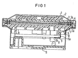
- the previous structure of a speech capsule is shown in FIG. 1 with the housing is designated, under the surface of which a damping ring 2 is arranged.
- a separating plate 3 is located under the damping ring.
- the transducer consists of a transducer plate 4 made of electrically conductive material and a disk-shaped piezoceramic, which is provided on both sides with electrodes over the entire surface.
- the piezoceramic provided with the electrodes is firmly connected to the transducer plate 4 by gluing.
- the converter is held by means of two silicone rings 5a and 5b.
- the pressure-contacted connection ribbon is not shown in the section shown.
- soldered connection ribbon 6 is guided between the converter plate 4 and the silicone ring 5 between a carrier 7 made of plastic and the housing made of metal to the component side 8 of an amplifier assembly 9 and soldered there to Griplet solder rivets 8.
- a plastic ring is designated, which protects the two connection tapes against the metal housing of the piezoelectric microphone short-circuit proof.
- An insulating material body 11 is provided in the lower region of the housing.
- the object of the invention is to improve the piezoelectric-acoustic transducer defined at the outset and shown in FIG. 1 in such a way that fully automatic soldering of the two connection tapes of the acoustic-electric transducer plate to the amplifier module of the microphone is made possible. Furthermore, the connection tapes are to be insulated against the metal housing with a label 10a instead of the plastic ring in a short-circuit-proof manner.
- connection points for the tapes allow a tolerance range for the soldering.
- a prerequisite for this type of automatic soldering of the connection tapes is an assembly sequence modified according to the invention, which is only possible with the aid of a workpiece carrier or with a corresponding workpiece holder.
- Devices of this type are the subject of subclaims 3 to 9.
- the separating plate is fixed in the necessary workpiece holder in such a way that the conductor track side is freely accessible. Silicone rings and converter plate are also pre-assembled on the workpiece carrier.
- the two connecting tapes cross the conductor track to which the tapes are soldered. With the help of two temperature-controlled bracket soldering devices, the tapes are soldered in a reflow soldering process.
- the carrier is then pressed onto the amplifier module from above. Amplifier assembly and carrier are swiveled and pressed into the partition plate.
- connection tapes are then protected against short-circuit protection by an automatically applied label against the metal housing of the piezo microphone.
- FIG. 1 a transistor microphone is shown in section, in which the connection tapes are contacted on the flat module 9 via Griplet solder rivets 8.
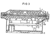
- the conductor tracks 12 can be seen, onto which the connecting tapes can be soldered within a certain tolerance range.
- FIG. 3 differs from FIG. 1 in that the Griplet solder rivets 8 are omitted and the strips are contacted on the conductor tracks 12.
- the adhesive label 10 for isolating the strips from the metal housing is shown.
- a workpiece carrier 13 comprises the unit of the structural holding elements, the separating plate 3, the silicone rings 5a and 5b and the transducer plate 4 with connecting tapes 6.
- the right part of the workpiece carrier is designed for receiving the amplifier flat module 9.
- FIG. 5 additionally shows a lifting device 14 for lifting the amplifier assembly into the soldering position.
- a reflow soldering head 15 is also indicated.
- FIG. 6 additionally shows the carrier feed and assembly stamp 16 in the raised position after the carrier has been put on.
- An additional device 17 is indicated schematically in FIG. 7, which pivots the carrier with the amplifier flat module in the direction of the arrow and mounts it in the unit of the structural holding element and transducer plate.
- the unit carrier with amplifier flat module is pivoted there with the aid of an additional device and structural holding elements and converter plate are mounted in the unit.
Landscapes
- Engineering & Computer Science (AREA)
- Acoustics & Sound (AREA)
- Signal Processing (AREA)
- Physics & Mathematics (AREA)
- Manufacturing & Machinery (AREA)
- Microelectronics & Electronic Packaging (AREA)
- Piezo-Electric Transducers For Audible Bands (AREA)
- Electric Connection Of Electric Components To Printed Circuits (AREA)
- Ceramic Products (AREA)
- Fuel-Injection Apparatus (AREA)
- Pressure Welding/Diffusion-Bonding (AREA)
- Details Of Audible-Bandwidth Transducers (AREA)
- Transducers For Ultrasonic Waves (AREA)
- Resistance Welding (AREA)
- Electrostatic, Electromagnetic, Magneto- Strictive, And Variable-Resistance Transducers (AREA)
Priority Applications (1)
| Application Number | Priority Date | Filing Date | Title |
|---|---|---|---|
| AT85103709T ATE28715T1 (de) | 1984-04-11 | 1985-03-27 | Piezoelektrisch-akustischer wandler fuer elektroakustische kapseln mit konstruktionsausfuehrung fuer die montage. |
Applications Claiming Priority (2)
| Application Number | Priority Date | Filing Date | Title |
|---|---|---|---|
| DE3413697 | 1984-04-11 | ||
| DE3413697 | 1984-04-11 |
Publications (2)
| Publication Number | Publication Date |
|---|---|
| EP0158230A1 true EP0158230A1 (fr) | 1985-10-16 |
| EP0158230B1 EP0158230B1 (fr) | 1987-07-29 |
Family
ID=6233308
Family Applications (1)
| Application Number | Title | Priority Date | Filing Date |
|---|---|---|---|
| EP85103709A Expired EP0158230B1 (fr) | 1984-04-11 | 1985-03-27 | Transducteur piézo-électrique-acoustique pour cellules électroacoustiques avec mise en oeuvre de construction pour l'assemblage |
Country Status (8)
| Country | Link |
|---|---|
| US (1) | US4674161A (fr) |
| EP (1) | EP0158230B1 (fr) |
| JP (1) | JPS60236599A (fr) |
| AT (1) | ATE28715T1 (fr) |
| AU (1) | AU573809B2 (fr) |
| BR (1) | BR8501679A (fr) |
| DE (1) | DE3560409D1 (fr) |
| FI (1) | FI80366C (fr) |
Families Citing this family (5)
| Publication number | Priority date | Publication date | Assignee | Title |
|---|---|---|---|---|
| ATE28715T1 (de) * | 1984-04-11 | 1987-08-15 | Siemens Ag | Piezoelektrisch-akustischer wandler fuer elektroakustische kapseln mit konstruktionsausfuehrung fuer die montage. |
| JP3992840B2 (ja) * | 1998-06-22 | 2007-10-17 | 北陸電気工業株式会社 | 圧電発音器及びその製造方法 |
| US6319054B1 (en) * | 2000-11-30 | 2001-11-20 | Avx Corporation | Electrical connector |
| US7978861B2 (en) * | 2004-05-17 | 2011-07-12 | Sperian Hearing Protection, Llc | Method and apparatus for continuous noise exposure monitoring |
| US8249266B2 (en) * | 2004-05-17 | 2012-08-21 | Sperian Hearing Protection, Llc | Filter system for hearing protection device for continuous noise exposure monitoring |
Citations (4)
| Publication number | Priority date | Publication date | Assignee | Title |
|---|---|---|---|---|
| US3500013A (en) * | 1966-07-07 | 1970-03-10 | Philips Corp | Method of making connections to a microcircuit |
| LU67103A1 (fr) * | 1972-02-29 | 1973-05-03 | ||
| EP0007436A1 (fr) * | 1978-07-17 | 1980-02-06 | Siemens Aktiengesellschaft | Transducteur électroacoustique avec une membrane munie d'une couche piézo-électrique |
| FR2530108A1 (fr) * | 1982-07-12 | 1984-01-13 | Geophysique Cie Gle | Nouvel hydrophone |
Family Cites Families (6)
| Publication number | Priority date | Publication date | Assignee | Title |
|---|---|---|---|---|
| US3331970A (en) * | 1964-09-29 | 1967-07-18 | Honeywell Inc | Sonic transducer |
| US3879726A (en) * | 1972-03-20 | 1975-04-22 | Mallory & Co Inc P R | Audible alarm unit |
| DE2820403C2 (de) * | 1978-05-10 | 1984-09-27 | Siemens AG, 1000 Berlin und 8000 München | Verfahren zum Ankleben und zum Kontaktieren eines elektrischen Bauteils mit einer flächenförmigen Elektrode |
| US4190784A (en) * | 1978-07-25 | 1980-02-26 | The Stoneleigh Trust, Fred M. Dellorfano, Jr. & Donald P. Massa, Trustees | Piezoelectric electroacoustic transducers of the bi-laminar flexural vibrating type |
| DE3007834A1 (de) * | 1980-02-29 | 1981-09-17 | Siemens AG, 1000 Berlin und 8000 München | Elektroakustischer wandler |
| ATE28715T1 (de) * | 1984-04-11 | 1987-08-15 | Siemens Ag | Piezoelektrisch-akustischer wandler fuer elektroakustische kapseln mit konstruktionsausfuehrung fuer die montage. |
-
1985
- 1985-03-27 AT AT85103709T patent/ATE28715T1/de not_active IP Right Cessation
- 1985-03-27 DE DE8585103709T patent/DE3560409D1/de not_active Expired
- 1985-03-27 EP EP85103709A patent/EP0158230B1/fr not_active Expired
- 1985-04-03 US US06/719,467 patent/US4674161A/en not_active Expired - Fee Related
- 1985-04-10 FI FI851418A patent/FI80366C/fi not_active IP Right Cessation
- 1985-04-10 BR BR8501679A patent/BR8501679A/pt not_active IP Right Cessation
- 1985-04-10 JP JP60076317A patent/JPS60236599A/ja active Granted
- 1985-04-10 AU AU40981/85A patent/AU573809B2/en not_active Ceased
Patent Citations (4)
| Publication number | Priority date | Publication date | Assignee | Title |
|---|---|---|---|---|
| US3500013A (en) * | 1966-07-07 | 1970-03-10 | Philips Corp | Method of making connections to a microcircuit |
| LU67103A1 (fr) * | 1972-02-29 | 1973-05-03 | ||
| EP0007436A1 (fr) * | 1978-07-17 | 1980-02-06 | Siemens Aktiengesellschaft | Transducteur électroacoustique avec une membrane munie d'une couche piézo-électrique |
| FR2530108A1 (fr) * | 1982-07-12 | 1984-01-13 | Geophysique Cie Gle | Nouvel hydrophone |
Also Published As
| Publication number | Publication date |
|---|---|
| FI80366C (fi) | 1990-05-10 |
| FI80366B (fi) | 1990-01-31 |
| EP0158230B1 (fr) | 1987-07-29 |
| US4674161A (en) | 1987-06-23 |
| JPS60236599A (ja) | 1985-11-25 |
| FI851418L (fi) | 1985-10-12 |
| ATE28715T1 (de) | 1987-08-15 |
| FI851418A0 (fi) | 1985-04-10 |
| AU4098185A (en) | 1985-10-17 |
| JPH0460400B2 (fr) | 1992-09-25 |
| BR8501679A (pt) | 1985-12-10 |
| AU573809B2 (en) | 1988-06-23 |
| DE3560409D1 (en) | 1987-09-03 |
Similar Documents
| Publication | Publication Date | Title |
|---|---|---|
| DE19719492C2 (de) | Vibratorvorrichtung | |
| DE68908808T2 (de) | Verfahren zum Montieren elektronischer Mikrokomponenten auf einer Unterlage und Zwischenprodukt. | |
| DE3125518C2 (de) | Verfahren zur Herstellung einer dünnen Verdrahtungsanordnung | |
| EP0140126A1 (fr) | Procédé de montage automatique sur bande | |
| DE69517002T2 (de) | Thermodruckkopf | |
| EP0218069A1 (fr) | Procédé de soudage au moyen de la lumière laser | |
| EP0112559A1 (fr) | Haut-parleur | |
| EP0762817A1 (fr) | Blindage pour des plaquettes de circuit | |
| DE2820403A1 (de) | Verfahren zur kontaktierung der klebstoffseitigen elektrode eines elektrischen bauteiles | |
| DE2810054A1 (de) | Elektronische schaltungsvorrichtung und verfahren zu deren herstellung | |
| DE2345149A1 (de) | Elektronisches hybrid-bauteil mit halbleiter-chips | |
| EP0158230B1 (fr) | Transducteur piézo-électrique-acoustique pour cellules électroacoustiques avec mise en oeuvre de construction pour l'assemblage | |
| DE10158529B4 (de) | Temperaturfühler | |
| DE4121449A1 (de) | Hoergeraet, insbesondere am kopf tragbares mini-hoergeraet, und verfahren zur herstellung | |
| DE4437476A1 (de) | Verbindungsleitung | |
| DE3138743A1 (de) | In einem dichten gehaeuse montiertes oberflaechenwellenfilter und dergleichen | |
| EP0061648B1 (fr) | Dispositif électrique dont la partie active est placée sur un support métallique et procédé pour la fabrication du dispositif | |
| EP0071917B1 (fr) | Dispositif électrique, groupement de dispositifs ou circuit intégré dont la partie active est placée sur un support métallique et procédé pour la fabrication du dispositif | |
| DE2546443C3 (de) | Zusammengesetzte Mikroschaltung und Verfahren zu ihrer Herstellung | |
| DE3436842C2 (fr) | ||
| WO1997008925A1 (fr) | Procede pour etablir une connexion entre au moins deux conducteurs electriques dont l'un est monte sur un substrat de support | |
| EP0702378B1 (fr) | Inductance de puce | |
| DE69303837T2 (de) | Gedruckter Schaltungsträger mit vorspringender Elektrode und Verbindungsverfahren | |
| DE7831808U1 (de) | Kleinhoergeraet | |
| EP0379624A1 (fr) | Composants semi-conducteurs pour montage en surface et procédé pour son montage en surface sur des supports |
Legal Events
| Date | Code | Title | Description |
|---|---|---|---|
| PUAI | Public reference made under article 153(3) epc to a published international application that has entered the european phase |
Free format text: ORIGINAL CODE: 0009012 |
|
| AK | Designated contracting states |
Designated state(s): AT BE CH DE FR GB IT LI LU NL SE |
|
| 17P | Request for examination filed |
Effective date: 19850827 |
|
| 17Q | First examination report despatched |
Effective date: 19860930 |
|
| GRAA | (expected) grant |
Free format text: ORIGINAL CODE: 0009210 |
|
| AK | Designated contracting states |
Kind code of ref document: B1 Designated state(s): AT BE CH DE FR GB IT LI LU NL SE |
|
| REF | Corresponds to: |
Ref document number: 28715 Country of ref document: AT Date of ref document: 19870815 Kind code of ref document: T |
|
| REF | Corresponds to: |
Ref document number: 3560409 Country of ref document: DE Date of ref document: 19870903 |
|
| ET | Fr: translation filed | ||
| ITF | It: translation for a ep patent filed | ||
| PLBE | No opposition filed within time limit |
Free format text: ORIGINAL CODE: 0009261 |
|
| STAA | Information on the status of an ep patent application or granted ep patent |
Free format text: STATUS: NO OPPOSITION FILED WITHIN TIME LIMIT |
|
| 26N | No opposition filed | ||
| ITTA | It: last paid annual fee | ||
| PGFP | Annual fee paid to national office [announced via postgrant information from national office to epo] |
Ref country code: LU Payment date: 19920318 Year of fee payment: 8 Ref country code: BE Payment date: 19920318 Year of fee payment: 8 |
|
| PGFP | Annual fee paid to national office [announced via postgrant information from national office to epo] |
Ref country code: FR Payment date: 19920323 Year of fee payment: 8 |
|
| PGFP | Annual fee paid to national office [announced via postgrant information from national office to epo] |
Ref country code: SE Payment date: 19920324 Year of fee payment: 8 |
|
| PGFP | Annual fee paid to national office [announced via postgrant information from national office to epo] |
Ref country code: CH Payment date: 19920622 Year of fee payment: 8 |
|
| EPTA | Lu: last paid annual fee | ||
| PGFP | Annual fee paid to national office [announced via postgrant information from national office to epo] |
Ref country code: GB Payment date: 19930216 Year of fee payment: 9 |
|
| PGFP | Annual fee paid to national office [announced via postgrant information from national office to epo] |
Ref country code: AT Payment date: 19930224 Year of fee payment: 9 |
|
| PG25 | Lapsed in a contracting state [announced via postgrant information from national office to epo] |
Ref country code: LU Free format text: LAPSE BECAUSE OF NON-PAYMENT OF DUE FEES Effective date: 19930327 |
|
| PG25 | Lapsed in a contracting state [announced via postgrant information from national office to epo] |
Ref country code: SE Effective date: 19930328 |
|
| PG25 | Lapsed in a contracting state [announced via postgrant information from national office to epo] |
Ref country code: LI Effective date: 19930331 Ref country code: CH Effective date: 19930331 Ref country code: BE Effective date: 19930331 |
|
| PGFP | Annual fee paid to national office [announced via postgrant information from national office to epo] |
Ref country code: NL Payment date: 19930331 Year of fee payment: 9 |
|
| PGFP | Annual fee paid to national office [announced via postgrant information from national office to epo] |
Ref country code: DE Payment date: 19930518 Year of fee payment: 9 |
|
| BERE | Be: lapsed |
Owner name: SIEMENS A.G. BERLIN UND MUNCHEN Effective date: 19930331 |
|
| PG25 | Lapsed in a contracting state [announced via postgrant information from national office to epo] |
Ref country code: FR Effective date: 19931130 |
|
| REG | Reference to a national code |
Ref country code: CH Ref legal event code: PL |
|
| REG | Reference to a national code |
Ref country code: FR Ref legal event code: ST |
|
| PG25 | Lapsed in a contracting state [announced via postgrant information from national office to epo] |
Ref country code: GB Effective date: 19940327 Ref country code: AT Effective date: 19940327 |
|
| PG25 | Lapsed in a contracting state [announced via postgrant information from national office to epo] |
Ref country code: NL Effective date: 19941001 |
|
| NLV4 | Nl: lapsed or anulled due to non-payment of the annual fee | ||
| GBPC | Gb: european patent ceased through non-payment of renewal fee |
Effective date: 19940327 |
|
| PG25 | Lapsed in a contracting state [announced via postgrant information from national office to epo] |
Ref country code: DE Effective date: 19941201 |
|
| EUG | Se: european patent has lapsed |
Ref document number: 85103709.3 Effective date: 19931008 |