EP0158442A2 - Procédé et dispositif pour produire des articles polymériques - Google Patents
Procédé et dispositif pour produire des articles polymériques Download PDFInfo
- Publication number
- EP0158442A2 EP0158442A2 EP85301671A EP85301671A EP0158442A2 EP 0158442 A2 EP0158442 A2 EP 0158442A2 EP 85301671 A EP85301671 A EP 85301671A EP 85301671 A EP85301671 A EP 85301671A EP 0158442 A2 EP0158442 A2 EP 0158442A2
- Authority
- EP
- European Patent Office
- Prior art keywords
- shot
- mixture
- constituents
- constituent
- demand
- Prior art date
- Legal status (The legal status is an assumption and is not a legal conclusion. Google has not performed a legal analysis and makes no representation as to the accuracy of the status listed.)
- Withdrawn
Links
- 229920000642 polymer Polymers 0.000 title claims description 26
- 238000000034 method Methods 0.000 title claims description 16
- 239000000470 constituent Substances 0.000 claims abstract description 84
- 239000000203 mixture Substances 0.000 claims abstract description 34
- 238000002156 mixing Methods 0.000 claims abstract description 26
- 229920002959 polymer blend Polymers 0.000 claims abstract description 20
- 230000000704 physical effect Effects 0.000 claims abstract description 11
- 239000002243 precursor Substances 0.000 claims abstract description 6
- 238000007599 discharging Methods 0.000 claims abstract description 5
- 230000007704 transition Effects 0.000 claims description 9
- 230000003247 decreasing effect Effects 0.000 claims description 2
- 239000012530 fluid Substances 0.000 claims 3
- 230000001419 dependent effect Effects 0.000 claims 1
- 239000011369 resultant mixture Substances 0.000 claims 1
- 239000006260 foam Substances 0.000 abstract description 12
- JOYRKODLDBILNP-UHFFFAOYSA-N Ethyl urethane Chemical compound CCOC(N)=O JOYRKODLDBILNP-UHFFFAOYSA-N 0.000 abstract description 4
- 238000004519 manufacturing process Methods 0.000 abstract description 3
- 239000000463 material Substances 0.000 description 10
- 238000010586 diagram Methods 0.000 description 5
- 238000000465 moulding Methods 0.000 description 4
- 229920005862 polyol Polymers 0.000 description 4
- 150000003077 polyols Chemical class 0.000 description 4
- 239000000126 substance Substances 0.000 description 3
- 239000000654 additive Substances 0.000 description 2
- 230000001186 cumulative effect Effects 0.000 description 2
- 239000004604 Blowing Agent Substances 0.000 description 1
- 229920005830 Polyurethane Foam Polymers 0.000 description 1
- 230000001133 acceleration Effects 0.000 description 1
- 238000004026 adhesive bonding Methods 0.000 description 1
- 238000004364 calculation method Methods 0.000 description 1
- 238000004590 computer program Methods 0.000 description 1
- 238000006073 displacement reaction Methods 0.000 description 1
- NBVXSUQYWXRMNV-UHFFFAOYSA-N fluoromethane Chemical group FC NBVXSUQYWXRMNV-UHFFFAOYSA-N 0.000 description 1
- 239000006261 foam material Substances 0.000 description 1
- 238000005187 foaming Methods 0.000 description 1
- 239000012948 isocyanate Substances 0.000 description 1
- IQPQWNKOIGAROB-UHFFFAOYSA-N isocyanate group Chemical group [N-]=C=O IQPQWNKOIGAROB-UHFFFAOYSA-N 0.000 description 1
- 239000011496 polyurethane foam Substances 0.000 description 1
- 235000020004 porter Nutrition 0.000 description 1
- 239000007779 soft material Substances 0.000 description 1
- 238000010561 standard procedure Methods 0.000 description 1
- 238000010408 sweeping Methods 0.000 description 1
- 210000000689 upper leg Anatomy 0.000 description 1
Images


Classifications
-
- B—PERFORMING OPERATIONS; TRANSPORTING
- B29—WORKING OF PLASTICS; WORKING OF SUBSTANCES IN A PLASTIC STATE IN GENERAL
- B29C—SHAPING OR JOINING OF PLASTICS; SHAPING OF MATERIAL IN A PLASTIC STATE, NOT OTHERWISE PROVIDED FOR; AFTER-TREATMENT OF THE SHAPED PRODUCTS, e.g. REPAIRING
- B29C44/00—Shaping by internal pressure generated in the material, e.g. swelling or foaming ; Producing porous or cellular expanded plastics articles
- B29C44/02—Shaping by internal pressure generated in the material, e.g. swelling or foaming ; Producing porous or cellular expanded plastics articles for articles of definite length, i.e. discrete articles
- B29C44/04—Shaping by internal pressure generated in the material, e.g. swelling or foaming ; Producing porous or cellular expanded plastics articles for articles of definite length, i.e. discrete articles consisting of at least two parts of chemically or physically different materials, e.g. having different densities
- B29C44/0492—Devices for feeding the different materials
-
- B—PERFORMING OPERATIONS; TRANSPORTING
- B01—PHYSICAL OR CHEMICAL PROCESSES OR APPARATUS IN GENERAL
- B01F—MIXING, e.g. DISSOLVING, EMULSIFYING OR DISPERSING
- B01F35/00—Accessories for mixers; Auxiliary operations or auxiliary devices; Parts or details of general application
- B01F35/80—Forming a predetermined ratio of the substances to be mixed
- B01F35/81—Forming mixtures with changing ratios or gradients
-
- B—PERFORMING OPERATIONS; TRANSPORTING
- B01—PHYSICAL OR CHEMICAL PROCESSES OR APPARATUS IN GENERAL
- B01F—MIXING, e.g. DISSOLVING, EMULSIFYING OR DISPERSING
- B01F35/00—Accessories for mixers; Auxiliary operations or auxiliary devices; Parts or details of general application
- B01F35/80—Forming a predetermined ratio of the substances to be mixed
- B01F35/83—Forming a predetermined ratio of the substances to be mixed by controlling the ratio of two or more flows, e.g. using flow sensing or flow controlling devices
- B01F35/831—Forming a predetermined ratio of the substances to be mixed by controlling the ratio of two or more flows, e.g. using flow sensing or flow controlling devices using one or more pump or other dispensing mechanisms for feeding the flows in predetermined proportion, e.g. one of the pumps being driven by one of the flows
-
- B—PERFORMING OPERATIONS; TRANSPORTING
- B01—PHYSICAL OR CHEMICAL PROCESSES OR APPARATUS IN GENERAL
- B01F—MIXING, e.g. DISSOLVING, EMULSIFYING OR DISPERSING
- B01F35/00—Accessories for mixers; Auxiliary operations or auxiliary devices; Parts or details of general application
- B01F35/80—Forming a predetermined ratio of the substances to be mixed
- B01F35/83—Forming a predetermined ratio of the substances to be mixed by controlling the ratio of two or more flows, e.g. using flow sensing or flow controlling devices
- B01F35/833—Flow control by valves, e.g. opening intermittently
-
- B—PERFORMING OPERATIONS; TRANSPORTING
- B29—WORKING OF PLASTICS; WORKING OF SUBSTANCES IN A PLASTIC STATE IN GENERAL
- B29B—PREPARATION OR PRETREATMENT OF THE MATERIAL TO BE SHAPED; MAKING GRANULES OR PREFORMS; RECOVERY OF PLASTICS OR OTHER CONSTITUENTS OF WASTE MATERIAL CONTAINING PLASTICS
- B29B7/00—Mixing; Kneading
- B29B7/02—Mixing; Kneading non-continuous, with mechanical mixing or kneading devices, i.e. batch type
- B29B7/22—Component parts, details or accessories; Auxiliary operations
- B29B7/28—Component parts, details or accessories; Auxiliary operations for measuring, controlling or regulating, e.g. viscosity control
-
- B—PERFORMING OPERATIONS; TRANSPORTING
- B29—WORKING OF PLASTICS; WORKING OF SUBSTANCES IN A PLASTIC STATE IN GENERAL
- B29B—PREPARATION OR PRETREATMENT OF THE MATERIAL TO BE SHAPED; MAKING GRANULES OR PREFORMS; RECOVERY OF PLASTICS OR OTHER CONSTITUENTS OF WASTE MATERIAL CONTAINING PLASTICS
- B29B7/00—Mixing; Kneading
- B29B7/30—Mixing; Kneading continuous, with mechanical mixing or kneading devices
- B29B7/58—Component parts, details or accessories; Auxiliary operations
- B29B7/60—Component parts, details or accessories; Auxiliary operations for feeding, e.g. end guides for the incoming material
- B29B7/603—Component parts, details or accessories; Auxiliary operations for feeding, e.g. end guides for the incoming material in measured doses, e.g. proportioning of several materials
-
- B—PERFORMING OPERATIONS; TRANSPORTING
- B29—WORKING OF PLASTICS; WORKING OF SUBSTANCES IN A PLASTIC STATE IN GENERAL
- B29B—PREPARATION OR PRETREATMENT OF THE MATERIAL TO BE SHAPED; MAKING GRANULES OR PREFORMS; RECOVERY OF PLASTICS OR OTHER CONSTITUENTS OF WASTE MATERIAL CONTAINING PLASTICS
- B29B7/00—Mixing; Kneading
- B29B7/30—Mixing; Kneading continuous, with mechanical mixing or kneading devices
- B29B7/58—Component parts, details or accessories; Auxiliary operations
- B29B7/72—Measuring, controlling or regulating
- B29B7/728—Measuring data of the driving system, e.g. torque, speed, power, vibration
-
- B—PERFORMING OPERATIONS; TRANSPORTING
- B29—WORKING OF PLASTICS; WORKING OF SUBSTANCES IN A PLASTIC STATE IN GENERAL
- B29B—PREPARATION OR PRETREATMENT OF THE MATERIAL TO BE SHAPED; MAKING GRANULES OR PREFORMS; RECOVERY OF PLASTICS OR OTHER CONSTITUENTS OF WASTE MATERIAL CONTAINING PLASTICS
- B29B7/00—Mixing; Kneading
- B29B7/74—Mixing; Kneading using other mixers or combinations of mixers, e.g. of dissimilar mixers ; Plant
- B29B7/7404—Mixing devices specially adapted for foamable substances
-
- B—PERFORMING OPERATIONS; TRANSPORTING
- B29—WORKING OF PLASTICS; WORKING OF SUBSTANCES IN A PLASTIC STATE IN GENERAL
- B29B—PREPARATION OR PRETREATMENT OF THE MATERIAL TO BE SHAPED; MAKING GRANULES OR PREFORMS; RECOVERY OF PLASTICS OR OTHER CONSTITUENTS OF WASTE MATERIAL CONTAINING PLASTICS
- B29B7/00—Mixing; Kneading
- B29B7/74—Mixing; Kneading using other mixers or combinations of mixers, e.g. of dissimilar mixers ; Plant
- B29B7/7404—Mixing devices specially adapted for foamable substances
- B29B7/7433—Plants
-
- B—PERFORMING OPERATIONS; TRANSPORTING
- B29—WORKING OF PLASTICS; WORKING OF SUBSTANCES IN A PLASTIC STATE IN GENERAL
- B29B—PREPARATION OR PRETREATMENT OF THE MATERIAL TO BE SHAPED; MAKING GRANULES OR PREFORMS; RECOVERY OF PLASTICS OR OTHER CONSTITUENTS OF WASTE MATERIAL CONTAINING PLASTICS
- B29B7/00—Mixing; Kneading
- B29B7/74—Mixing; Kneading using other mixers or combinations of mixers, e.g. of dissimilar mixers ; Plant
- B29B7/7457—Mixing heads without moving stirrer
-
- B—PERFORMING OPERATIONS; TRANSPORTING
- B29—WORKING OF PLASTICS; WORKING OF SUBSTANCES IN A PLASTIC STATE IN GENERAL
- B29B—PREPARATION OR PRETREATMENT OF THE MATERIAL TO BE SHAPED; MAKING GRANULES OR PREFORMS; RECOVERY OF PLASTICS OR OTHER CONSTITUENTS OF WASTE MATERIAL CONTAINING PLASTICS
- B29B7/00—Mixing; Kneading
- B29B7/74—Mixing; Kneading using other mixers or combinations of mixers, e.g. of dissimilar mixers ; Plant
- B29B7/7471—Mixers in which the mixing takes place at the inlet of a mould, e.g. mixing chambers situated in the mould opening
-
- B—PERFORMING OPERATIONS; TRANSPORTING
- B29—WORKING OF PLASTICS; WORKING OF SUBSTANCES IN A PLASTIC STATE IN GENERAL
- B29B—PREPARATION OR PRETREATMENT OF THE MATERIAL TO BE SHAPED; MAKING GRANULES OR PREFORMS; RECOVERY OF PLASTICS OR OTHER CONSTITUENTS OF WASTE MATERIAL CONTAINING PLASTICS
- B29B7/00—Mixing; Kneading
- B29B7/74—Mixing; Kneading using other mixers or combinations of mixers, e.g. of dissimilar mixers ; Plant
- B29B7/76—Mixers with stream-impingement mixing head
- B29B7/7615—Mixers with stream-impingement mixing head characterised by arrangements for controlling, measuring or regulating, e.g. for feeding or proportioning the components
-
- G—PHYSICS
- G05—CONTROLLING; REGULATING
- G05D—SYSTEMS FOR CONTROLLING OR REGULATING NON-ELECTRIC VARIABLES
- G05D11/00—Control of flow ratio
- G05D11/02—Controlling ratio of two or more flows of fluid or fluent material
- G05D11/13—Controlling ratio of two or more flows of fluid or fluent material characterised by the use of electric means
- G05D11/131—Controlling ratio of two or more flows of fluid or fluent material characterised by the use of electric means by measuring the values related to the quantity of the individual components
- G05D11/133—Controlling ratio of two or more flows of fluid or fluent material characterised by the use of electric means by measuring the values related to the quantity of the individual components with discontinuous action
-
- B—PERFORMING OPERATIONS; TRANSPORTING
- B29—WORKING OF PLASTICS; WORKING OF SUBSTANCES IN A PLASTIC STATE IN GENERAL
- B29K—INDEXING SCHEME ASSOCIATED WITH SUBCLASSES B29B, B29C OR B29D, RELATING TO MOULDING MATERIALS OR TO MATERIALS FOR MOULDS, REINFORCEMENTS, FILLERS OR PREFORMED PARTS, e.g. INSERTS
- B29K2995/00—Properties of moulding materials, reinforcements, fillers, preformed parts or moulds
- B29K2995/0037—Other properties
- B29K2995/0044—Anisotropic
-
- B—PERFORMING OPERATIONS; TRANSPORTING
- B29—WORKING OF PLASTICS; WORKING OF SUBSTANCES IN A PLASTIC STATE IN GENERAL
- B29K—INDEXING SCHEME ASSOCIATED WITH SUBCLASSES B29B, B29C OR B29D, RELATING TO MOULDING MATERIALS OR TO MATERIALS FOR MOULDS, REINFORCEMENTS, FILLERS OR PREFORMED PARTS, e.g. INSERTS
- B29K2995/00—Properties of moulding materials, reinforcements, fillers, preformed parts or moulds
- B29K2995/0037—Other properties
- B29K2995/0063—Density
- B29K2995/0064—Non-uniform density
-
- B—PERFORMING OPERATIONS; TRANSPORTING
- B29—WORKING OF PLASTICS; WORKING OF SUBSTANCES IN A PLASTIC STATE IN GENERAL
- B29L—INDEXING SCHEME ASSOCIATED WITH SUBCLASS B29C, RELATING TO PARTICULAR ARTICLES
- B29L2031/00—Other particular articles
- B29L2031/58—Upholstery or cushions, e.g. vehicle upholstery or interior padding
-
- B—PERFORMING OPERATIONS; TRANSPORTING
- B29—WORKING OF PLASTICS; WORKING OF SUBSTANCES IN A PLASTIC STATE IN GENERAL
- B29L—INDEXING SCHEME ASSOCIATED WITH SUBCLASS B29C, RELATING TO PARTICULAR ARTICLES
- B29L2031/00—Other particular articles
- B29L2031/751—Mattresses, cushions
Definitions
- This invention relates to a method and apparatus for producing a moulded polymer article, and more particularly to such a method and apparatus wherein a plurality of shots of polymer are sequentially formed to comprise the charge to a mould.
- the standard procedure for forming moulded polymer articles is to mix the hardenable precursor constituents in a predetermined ratio calculated to yield the desired properties in the product and to discharge the polymer mixture into a mould for forming the article. All portions of the article then would have the same properties.
- a method and apparatus for producing isotropic foamed stock, for example, is disclosed in US-A-3606903 (Porter et al). Where it is desirable to have the properties vary from one portion of the article to another, then it is necessary to place polymer mixtures of different constituent ratios in different parts of the mould to obtain the desired variation in properties. For example, in the case of automobile seat cushions it is desired to have firm lateral edges on the seat and a soft centre.
- Such seats have been obtained by separately moulding the edges and centre portions and then gluing them together or by moulding inserts of hard or soft material in the main foam seat. These require separate moulding stages for the inserts and the remainder of the seat. It has been proposed to mould a seat of variable density or hardness of foam in a single stage utilizing a number of mixing heads with separate discharge nozzles for charging separate parts of a mould and then foaming the material. Such an arrangement requires duplication of metering, mixing and discharge apparatus and the controls therefor for each desired polymer property. It would be desirable however to obtain the variable properties in a single article or variations from one article to another using only a single metering, mixing and discharge arrangement.
- the invention is carried out by the method of delivering precursor constituents to a mixing head at predetermined rates of flow for mixing and discharging into a mould to form a polymer with a first physical property and changing the relative rates of flow of the constituents to obtain another mixture for discharging into the mould which results in a polymer with a second physical property so that the moulded article will have regions of different physical properties.
- the invention is further carried out by forming a plurality of shots of polymer of different ratios or kinds of constituents wherein each shot is formed by establishing demand count rates for each constituent, simultaneously and gradually changing the count rates at the beginning and end of each shot, controlling the flow of each constituent to rates representing and tracking the established count rates, and forming new demand count rates for other shots which result in the change of at least some of the flow rates to obtain new mixtures or constituent ratios, thereby providing to a mould mixtures for producing different properties at different parts of the moulded article.
- the invention further contemplates an apparatus for carrying out the above method using a pump for supplying each constituent to the mixing head, a control, a feedback control responsive to the flow of each constituent, a computer for receiving and storing data specifying the constituent amounts for each shot of polymer, the computer being programmed to establish the demand values and to change the demand values as required to set the constituent ratios for each of a plurality of shots to make the change from one shot to another, and a controller responsive to the computer and to the feedback control to control each pump to deliver the desired amounts of constituents to the mixing head so that the mixture discharged from the nozzle is established by the computer.
- the invention is described herein in terms of the manufacture of polyurethane foam automotive seats, however the method and apparatus of the invention applies to the manufacture of polymer articles especially where varying polymer properties are required in an article and is also useful where different polymer mixtures are to be applied to successive moulds.
- foam automobile seats it is desirable to alter the hardness and density of the foam for various seat styles and applications.
- the foam used for seat cushions is firmer and more dense than foam used in seat backs.
- Optimum seat comfort requires that a portion of a cushion or a back be harder or softer than another portion.
- the wide range of variables necessary to accommodate these differing requirements can be derived from six independent material streams properly combined. Thus, a six component system is described herein but it is apparent that a larger or smaller number of components may be used without departing from the inventive concept.
- one constituent is isocyanate which serves as the reactive component.
- Another constituent is the polyol and additives necessary to produce foam in a density range used for seat cushions and another constituent contains the polyol and additives to produce foam for seat backs.
- Two further constituents are pure soft polyol and pure hard polyol.
- the sixth constituent is a fluorocarbon blowing agent.
- the flow rate of each constituent is substantially infinitely variable so that the exact hardness/density combination can be achieved. In addition, each flow rate can be changed extremely rapidly so that the resulting polymer mixture can be changed almost instantaneously.
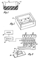
- Figure 1 illustrates a cross section of an automotive bucket seat cushion 10 having a relatively soft centre support 12 and a lateral wing 14 on each side of harder foam material to provide firm lateral thigh support.
- one mixture of material is used for the two wings 14 and a second mixture is used for the centre 12.
- the two materials are foamed in a mould simultaneously so that the wings and centre portion are continuous and form an integral structure.
- the lower half of the mould 16 for moulding the seat cushion 10 has deposited therein three separate shots of polymer mixture identified as shots 12a in the centre and 14a on either side and spaced therefrom which when foamed with a mould top (not shown) in place will form the wings 1 4 and centre 12 of the cushion.
- the two types of material are discharged into the mould from a single nozzle in the sequence 14a, 12a, 14a, so that the polymer mixture changes twice during the charging of the mould 16.
- the polymer blending system as shown in Figure 3 comprises six containers 18, one for each constituent identified above, and each is connected through a pump 20 and feed line 22 to a mixing head 24 where the separate streams of material are blended and emitted through a discharge nozzle 26 into a mould 16 which is carried past the discharge nozzle by a conveyor 28.
- Each pump 20 is driven by a motor 30 which has its speed and hence the pump output controlled by a controller 32 which in turn has its operation controlled by a computer 34.
- the motors 30 are hydraulic motors each controlled by a servo valve 36 coupled to a single hydraulic source 38.
- An analog tachometer 40 and a digital encoder 42 are mechanically coupled to each motor/pump combination to provide feedback signals to the controller 32 indicating pump speed and the amount of pump rotation.
- the encoder 42 preferably produces 1,000 pulses per revolution.
- the pumps are highly accurate positive displacement chemical pumps so that the tachometer signal as well as the encoder pulse rate are accurate representations of material flow rate and in addition the cumulative encoder pulses generated in a given period is an accurate indication of the cumulative amount of material delivered during that period.
- control system comprises a computer such as a Hewlett-Packard HP1000 mini-computer 34 which is coupled to input/ output interface equipment 46 such as a Hewlett-Packard Multi-Programmer.
- the interface is tied to a master frequency circuit 48 which provides a common pacing signal or master frequency, and to servo drive circuits 50, one for controlling each pump.
- the interface 46 comprises a group of several circuit cards each having a particular interface function.
- a master digital output card 52 is connected to the master frequency circuit 48 and supplies thereto a digital signal which controls the frequency which is sent out to all the servo drive circuits 50.
- the interface 46 For each servo drive circuit 50 the interface 46 contains a digital output card 54, a counter card 56 to receive encoder pulses from the servo circuit, a digital input card 58 which receives an error signal from the servo circuit, and an analog/digital card 60 for receiving the tachometer signal from the servo circuit 50. At least one digital output card 62 for supplying an enable signal to each servo circuit is included in the interface 46. Other cards, as needed, may be included.
- the interface 46 is shown again in Figure 5 as is the frequency circuit 48 and a detailed block diagram of a servo drive circuit 50, along with the associated servo valve 36, hydraulic motor 30, tachometer 40 and encoder 42.
- the digital output 52 sends to the frequency circuit 48 a digital signal which is the master frequency command.
- the master frequency output by the frequency circuit 48 is one megahertz.
- the master frequency can be reduced to facilitate the programming of lower flow rates.
- the master frequency can be appropriately altered by the computer command.
- the frequency circuit 48 comprises a digital to voltage converter responsive to the master frequency command from the digital output 52 and a voltage to frequency converter to produce the master frequency corresponding to the digital command.
- the frequency circuit 48 also produces a clock output. The master frequency and the clock outputs are coupled to each of the servo drive circuits 50.
- a typical servo drive circuit 50 is shown in Figure 5.
- a divider 64 receives the master frequency signal from the frequency circuit 48, the enable signal from the digital output 62 and a divisor from the digital output 54.
- the divider produces an output on line 66 which is a frequency equal to the master frequency divided by the divisor.
- the output frequency on line 66 is termed the "demand count rate". Since the computer determines both the master frequency and the divisor it directly controls the demand count rate.
- the chief function of the servo drive circuit 50 is to control its associated pump to ensure that the constituent flow rate is proportional to the demand count rate. This is accomplished by detecting the actual flow rate by the encoder 42. The encoder output frequency is called the measured count rate.
- That signal is fed to a directional circuit 68 which transmits forward and reverse pulse signals on lines 70 and 72 respectively.
- the reverse pulses can occur during idle conditions of the pump where some mechanical drift would allow minor reverse motion.
- Another output 74 of the directional circuit transfers the net forward count pulses to the interface counter card 56 which accumulates a value proportional to the. amount of material delivered by the pump.
- Mixer circuit 76 combines the demand count rate signal on line 66 and the reverse pulse signal on line 72 to provide an output on line 78 which along with the signal on line 70 provides inputs to a forward/reverse pulse separator circuit 80.
- the latter circuit is controlled . by a clock frequency and transmits the forward and reverse pulses to an up/down counter 82.
- the separator circuit 80 assures that the up and the down pulses fed to the counter are sequenced in time so that every pulse is registered by the counter which serves as a subtractor.
- the counter 82 compares the demand count rate/ reverse pulse signal of line 78 with the measured forward signal pulse by pulse to determine any difference between the two sets of pulses. Any difference or error is fed out on line 84 and is operated upon first by a digital to analog converter 86 and then by an amplifier 88 which drives the servo valve 36 to a degree determined by the error magnitude thereby closing the servo control loop.
- the loop has sufficiently high gain that the measured count rate closely tracks the demand count rate thereby resulting in very small errors.
- the error on line 84 is on the order of 3 or 4 pulses even though the count rates may be on the order of a few hundred or a few thousand pulses per second.
- the error on line 84 is coupled to the interface digital input 58 so that the computer can internally compare the error with a preset tolerance value and if the value is exceeded the computer terminates the system operation as though the shot had been completed.
- Another check on the operation utilizes the analog tachometer 40 output signal which is fed through a filter 90 and then transmitted to an analog to digital converter 60 in the interface 46. The computer compares that speed signal with the demand count rate and if there is a large variance the computer terminates the system operation.
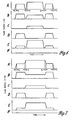
- Figure 6 illustrates graphically how the constituent ratios may change with time to form the three shots of polymer mixture shown in Figure 2 wherein the first and third shots 14a have ratios yielding certain foam properties while the second shot l2a has different constituent ratios and different properties.
- the graphs show constituent flow rates versus time.
- constituent A flows at a greater rate for the second shot than it does for the first and third
- constituent B flows at a lesser rate for a second shot than for the first and third shots.
- Constituent C on the other hand, has zero flow for the first and third shot but for the second shot has a flow rate which is smaller than either A or B.
- Constituent D flows at the same rate as A during the first and third shots but has zero flow for the second shot.
- Constituent E like A, has a greater flow rate for the second shot than for the other two but the variation between the high and low rates is greater than in the case of A.
- Constituent F is not utilized at all.
- each shot when it is initiated and terminated changes gradually between its zero and its nominal operating value. These initial and terminal ramps allow for accurately controlled pump acceleration and deceleration so that each pump is brought up to its desired speed or brought back down to zero speed in synchronism with the other pumps thereby maintaining the same constituent ratios even in the transition stages of each shot.
- the ramp times t equal 0.1 second and since the system is digitally controlled the ramps take place in stepped increments of preferably 10 steps in each ramp. However, the pump inertia effectively filters these steps to produce a linear change in flow rate as illustrated.
- the computer controls the slope of the ramp by controlling the demand count rate that in turn is controlled by changing the master frequency or the divisor inputs to the divider 64. That is, the master frequency can be maintained at a standard value while the divisor changes in the ramp fashion from its highest value representing a low flow rate to the value corresponding to the desired flow rate of that constituent.
- the divisor is not large enough to cause a zero flow rate, so the pumps are turned on and off at the beginning and end of each shot by controlling the enable input to the divider 64.
- the ramps may be generated by sweeping the master frequency from zero to its standard value or vice versa and holding the divisors constant for the duration of each shot. In either case the ramps are executed synchronously.
- the initial ramp of the first shot and the terminal ramp of the third shot are effected by changing the master frequency whereas the remaining ramps are controlled by changing the divisor.
- a further feature evident in the waveforms of Figure 6 is a dwell time t d between adjacent shots.
- the dwell time t d typically may be of the order of 0.1 second or more, however, zero dwell time is a viable option.
- Figure 7, like Figure 6, represents the flow rates of several constituents during the blending of chemicals for three consecutive shots.
- Figure 7 is different from Figure 6 in that the transition between adjacent shots is accomplished without stopping the flow of each constituent. Rather the change of flow rate of each constituent is accomplished by a direct ramp change from the old value to the new value. This is accomplished by linearly changing the divisor in several steps over the transition period. In this manner the transition is made more quickly than in the case of Figure 6 but does not allow a dwell time between shots and during the transition period the ratios of the various constituents is a changing blend of ratios of the adjacent shots.
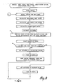
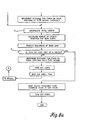
- FIG. 8 and 8a together show a flow chart representing the computer program for controlling the urethane polymer mixtures for a number of shots in series as shown in Figure 6 with a dwell time between adjacent shots.
- the initial ramp of the first shot and the terminal ramp of the last shot are controlled by changing the master frequency while the remaining ramps are controlled by changing the divisors.
- the first several steps include feeding in the data as shown in Tables 1 and 2 for several different shots as well as the dwell time between shots and calculating the values set forth in Tables 1 and 2.
- each divisor is divided into ten increments to prepare for changing the divisors.
- step B if the forthcoming shot is the first of a series the divisors are set at the calculated values, the pumps are turned on and the master frequency is increased from a low value to the standard value. If it is not the first shot of the series then the divisors are set at a maximum value to call for very slow pump rotation, the pumps are turned on and then the divisors are changed down to the calculated values.
- step C the total counts are accumulated throughout each shot to determine how near the shot is to completion. Then to predict when the down ramps should begin the number of counts that will occur during the down ramp is calculated and that value is subtracted from the total counts required for the individual shot size thereby determining the count value at the beginning of the down ramp.
- step D if the current shot is not the last one of a series, then the divisors are changed down and the pumps turned off and they remain off for the dwell time. Thereafter the program loops back to the recall inputs step E for
- the master frequency is changed down to the low value and the pumps turned off to terminate the charging of the mould and to end the program.
Landscapes
- Engineering & Computer Science (AREA)
- Mechanical Engineering (AREA)
- Chemical & Material Sciences (AREA)
- Chemical Kinetics & Catalysis (AREA)
- Physics & Mathematics (AREA)
- General Physics & Mathematics (AREA)
- Automation & Control Theory (AREA)
- Casting Or Compression Moulding Of Plastics Or The Like (AREA)
- Processing And Handling Of Plastics And Other Materials For Molding In General (AREA)
- Molding Of Porous Articles (AREA)
Applications Claiming Priority (2)
| Application Number | Priority Date | Filing Date | Title |
|---|---|---|---|
| US06/596,945 US4571319A (en) | 1984-04-05 | 1984-04-05 | Method and apparatus for producing polymer articles having different properties in different regions of the articles |
| US596945 | 1984-04-05 |
Publications (2)
| Publication Number | Publication Date |
|---|---|
| EP0158442A2 true EP0158442A2 (fr) | 1985-10-16 |
| EP0158442A3 EP0158442A3 (fr) | 1987-12-16 |
Family
ID=24389384
Family Applications (1)
| Application Number | Title | Priority Date | Filing Date |
|---|---|---|---|
| EP85301671A Withdrawn EP0158442A3 (fr) | 1984-04-05 | 1985-03-11 | Procédé et dispositif pour produire des articles polymériques |
Country Status (5)
| Country | Link |
|---|---|
| US (1) | US4571319A (fr) |
| EP (1) | EP0158442A3 (fr) |
| JP (1) | JPS6122911A (fr) |
| CA (1) | CA1235869A (fr) |
| ES (1) | ES8606075A1 (fr) |
Cited By (5)
| Publication number | Priority date | Publication date | Assignee | Title |
|---|---|---|---|---|
| GB2215266A (en) * | 1988-03-11 | 1989-09-20 | Rotational Mouldings Ltd | Moulded objects |
| FR2728362A1 (fr) * | 1994-12-15 | 1996-06-21 | Aubry Eric | Procede et dispositif pour le dosage d'un adjuvant, en particulier dans un melange de polymeres |
| WO2007026315A3 (fr) * | 2005-09-01 | 2007-08-02 | Procter & Gamble | Systeme de commande de la combinaison de matieres et procede correspondant |
| US8602633B2 (en) | 2005-09-01 | 2013-12-10 | The Procter & Gamble Company | Control system for and method of combining materials |
| US8616760B2 (en) | 2005-09-01 | 2013-12-31 | The Procter & Gamble Company | Control system for and method of combining materials |
Families Citing this family (38)
| Publication number | Priority date | Publication date | Assignee | Title |
|---|---|---|---|---|
| DE3505155A1 (de) * | 1985-02-15 | 1986-08-21 | Elastogran Maschinenbau GmbH, 2844 Lemförde | Vorrichtung zur herstellung von formteilen aus mehrkomponentenkunststoff, insbesondere polyurethan, mit einer programmsteuerung |
| US5316701A (en) * | 1985-08-19 | 1994-05-31 | Payne Leroy | Multiaxis rotational molding process |
| US5503780A (en) * | 1985-08-19 | 1996-04-02 | Payne; Leroy | Multiaxis rotational molding method |
| US6555037B1 (en) * | 1985-08-19 | 2003-04-29 | Payne Leroy | Multiaxis rotational molding method and apparatus |
| US4956135A (en) * | 1985-08-19 | 1990-09-11 | Le Roy Payne | Molding apparatus and method |
| US4741972A (en) * | 1986-12-15 | 1988-05-03 | Hardigg Industries | Rotomold insert |
| US4931249A (en) * | 1987-04-20 | 1990-06-05 | Thermal Designs, Inc. | Apparatus and process for mixing and dispensing high viscosity, multiple component reactive liquids into a mold |
| JPS63278812A (ja) * | 1987-05-11 | 1988-11-16 | Chisso Corp | 熱可塑性樹脂のプレス成形方法 |
| JP2542119B2 (ja) * | 1989-11-01 | 1996-10-09 | ポリプラスチックス株式会社 | 熱可塑性相互侵入網目構造体及びその形成法 |
| US5136515A (en) * | 1989-11-07 | 1992-08-04 | Richard Helinski | Method and means for constructing three-dimensional articles by particle deposition |
| US5614135A (en) * | 1990-01-18 | 1997-03-25 | Henderson's Industries Pty. Ltd. | Moulding processes and apparatus |
| DE69206443T2 (de) * | 1991-01-31 | 1996-05-30 | Texas Instruments Inc | Verfahren und Vorrichtung zur rechnergesteuerten Herstellung von dreidimensionalen Gegenständen aus Rechnerdaten. |
| US5464585A (en) * | 1994-01-03 | 1995-11-07 | Metton America, Inc. | Method of injection molding articles with selective concentrations or gradients of materials |
| DE4405427C1 (de) * | 1994-02-21 | 1995-11-02 | Hennecke Gmbh Maschf | Verfahren und Vorrichtung zur Herstellung von endlosen Polyurethan-Formkörpern |
| US5804110A (en) * | 1994-10-06 | 1998-09-08 | Foamseal, Inc. | Control for spraying foam into hollow body cavities |
| US5798064A (en) * | 1996-12-23 | 1998-08-25 | Cabot Safety Intermediate Corp | Process and apparatus for fabrication of flexible foam |
| DE10062420A1 (de) * | 2000-12-14 | 2002-07-11 | Hennecke Gmbh | Verfahren und Vorrichtung zum Herstellen von Füllstoff-haltigen Formteilen |
| US6734020B2 (en) * | 2001-03-07 | 2004-05-11 | Applied Materials, Inc. | Valve control system for atomic layer deposition chamber |
| WO2002100916A1 (fr) * | 2001-05-24 | 2002-12-19 | Mitsui Takeda Chemicals, Inc. | Procede et appareil de production de mousses de polyurethane flexibles |
| US6983997B2 (en) | 2001-06-29 | 2006-01-10 | Haworth, Inc. | Chair having a suspension seat assembly |
| US6640349B2 (en) * | 2001-08-02 | 2003-11-04 | Centoco Plastics Limited | Toilet seat |
| DE10248639B4 (de) * | 2002-10-18 | 2005-03-17 | Ticona Gmbh | Verfahren und Vorrichtung zur kombinatorischen Herstellung von Mischungen sowie deren Verwendung |
| GB2395160A (en) * | 2002-11-12 | 2004-05-19 | Bamford Excavators Ltd | A moulding arrangement in association with mixing |
| US20070047384A1 (en) * | 2005-09-01 | 2007-03-01 | Mclaughlin Jon K | Control system for and method of combining materials |
| JP5067892B2 (ja) * | 2006-10-31 | 2012-11-07 | 株式会社ライセンス&プロパティコントロール | アンカーとその固定方法及びそれを用いた固定構造 |
| JP2009121507A (ja) * | 2007-11-12 | 2009-06-04 | Tokuichi Nakano | アンカープラグ |
| US20090127912A1 (en) * | 2007-11-19 | 2009-05-21 | Lear Corporation | Vehicle seat assembly having a cushion with a colored coating and method of making the same |
| DE102008035947B4 (de) | 2008-07-31 | 2015-03-26 | Kraussmaffei Technologies Gmbh | Verfahren zur Herstellung eines Produktes aus reaktiven Ausgangsstoffen |
| JP2013500885A (ja) * | 2009-08-07 | 2013-01-10 | バイエル・マテリアルサイエンス・アクチェンゲゼルシャフト | 高速高分子反応系を加工するための装置 |
| US8998309B2 (en) | 2013-01-10 | 2015-04-07 | Lear Corporation | Vehicle seat assembly having a permeable cushion with a colored coating and method of making the same |
| JP6600134B2 (ja) * | 2014-11-25 | 2019-10-30 | 株式会社東洋クオリティワン | クッションパッド |
| DE102015108086A1 (de) * | 2015-05-21 | 2016-11-24 | "Klöckner Desma Schuhmaschinen GmbH" | Verfahren zur Herstellung von technischen Objekten |
| US11279072B2 (en) | 2019-03-27 | 2022-03-22 | Omachron Intellectual Property Inc. | Extruder with feed block for promoting increased mass transport rate |
| US11161275B2 (en) | 2019-03-27 | 2021-11-02 | Omachron Intellectual Property Inc. | Modular extruder |
| US10870226B2 (en) * | 2019-03-27 | 2020-12-22 | Omachron Intellectual Property Inc. | Apparatus and methods using multiple extruders |
| CN114829441A (zh) * | 2019-12-17 | 2022-07-29 | 巴斯夫欧洲公司 | 制备绝热制品的弹性的发泡方法 |
| US20220347928A1 (en) * | 2021-04-29 | 2022-11-03 | Raytheon Company | Additive manufacturing system for lightweight large scale sandwich structures with tailorable core densities |
| CN114770851B (zh) * | 2022-04-12 | 2024-02-06 | 长虹美菱股份有限公司 | 一种冰箱门体的发泡注料方法 |
Family Cites Families (23)
| Publication number | Priority date | Publication date | Assignee | Title |
|---|---|---|---|---|
| US3064173A (en) * | 1956-05-18 | 1962-11-13 | Celanese Corp | Speed slaving method and apparatus |
| US3020587A (en) * | 1958-04-03 | 1962-02-13 | Sterling Alderfer Company | Process and apparatus for the manufacture of sealing strips or gaskets |
| NL268636A (fr) * | 1960-08-25 | 1900-01-01 | ||
| FR1399636A (fr) * | 1964-04-06 | 1965-05-21 | Lignes Telegraph Telephon | Perfectionnements aux systèmes de régulation pour mélanges à proportions constantes |
| US3231801A (en) * | 1964-09-02 | 1966-01-25 | Nat Standard Co | Plural motor master-slave control system employing pulse responsive electronic transmission |
| US3257149A (en) * | 1964-12-28 | 1966-06-21 | Gen Motors Corp | Seat pad formation |
| US3478767A (en) * | 1965-01-27 | 1969-11-18 | Foxboro Co | Gated oscillator digital controller |
| US3606903A (en) * | 1968-01-30 | 1971-09-21 | Upjohn Co | Method and apparatus for producing isotropic foamed stock |
| DE2004387A1 (de) * | 1970-01-31 | 1971-09-30 | Deutsche Edelstahlwerke Ag | Wendeschneidplatte für Kopierdrehmeißel |
| US3888612A (en) * | 1971-01-28 | 1975-06-10 | Ici Ltd | Injection moulding means for forming a composite product |
| US3801684A (en) * | 1971-01-28 | 1974-04-02 | Ici Ltd | Injection moulding |
| US3984510A (en) * | 1974-08-29 | 1976-10-05 | Cincinnati Milacron, Inc. | Ratio controlled mixing of liquids |
| US4073839A (en) * | 1976-04-19 | 1978-02-14 | The Goodyear Tire & Rubber Company | Method of zone pouring foam products |
| DE2631167C3 (de) * | 1976-07-10 | 1985-01-31 | Bayer Ag, 5090 Leverkusen | Verfahren zur Herstellung von massiven Formteilen |
| US4199303A (en) * | 1976-09-29 | 1980-04-22 | Gusmer Corporation | Feeder for apparatus for ejecting a mixture of a plurality of liquids |
| DE2700875C2 (de) * | 1977-01-11 | 1978-12-21 | Apparatebau Gauting Gmbh, 8035 Gauting | Mischanordnung für eine erste flüssige Komponente mit mindestens einer weiteren flüssigen Komponente |
| US4328549A (en) * | 1980-01-11 | 1982-05-04 | Olin Corporation | Process flow computer control system |
| US4312820A (en) * | 1980-08-21 | 1982-01-26 | General Motors Corporation | Process and apparatus for nucleation control adapted for reaction injection molding of cellular products |
| DE3102140A1 (de) * | 1981-01-23 | 1982-08-19 | Bayer Ag, 5090 Leverkusen | Formteil, insbesondere polster fuer fahrzeugsitze, aus polyurethanschaumstoff mit zonen unterschiedlicher eindruckhaerte und verfahren zu seiner herstellung |
| DE3110303C2 (de) * | 1981-03-17 | 1984-05-17 | Herbert Dr.-Ing. 8032 Lochham Funck | Verfahren und Vorrichtung zum Herstellen von mehrschichtigen Formkörpern aus mindestens zwei PUR-Schaumsystemen |
| US4399105A (en) * | 1981-03-30 | 1983-08-16 | The Upjohn Company | Programmable computer controlled reaction injection mixing head system |
| CA1194660A (fr) * | 1981-06-27 | 1985-10-08 | Rudolf J. Tenhagen | Methode de production de la mousse de polyurethane |
| JPS5896530A (ja) * | 1981-12-03 | 1983-06-08 | Nissan Motor Co Ltd | 発泡樹脂製パネル部材の製造方法 |
-
1984
- 1984-04-05 US US06/596,945 patent/US4571319A/en not_active Expired - Fee Related
-
1985
- 1985-01-16 CA CA000472152A patent/CA1235869A/fr not_active Expired
- 1985-03-11 EP EP85301671A patent/EP0158442A3/fr not_active Withdrawn
- 1985-04-03 ES ES541938A patent/ES8606075A1/es not_active Expired
- 1985-04-05 JP JP60071330A patent/JPS6122911A/ja active Pending
Cited By (8)
| Publication number | Priority date | Publication date | Assignee | Title |
|---|---|---|---|---|
| GB2215266A (en) * | 1988-03-11 | 1989-09-20 | Rotational Mouldings Ltd | Moulded objects |
| GB2215266B (en) * | 1988-03-11 | 1991-11-13 | Rotational Mouldings Ltd | Moulded objects |
| FR2728362A1 (fr) * | 1994-12-15 | 1996-06-21 | Aubry Eric | Procede et dispositif pour le dosage d'un adjuvant, en particulier dans un melange de polymeres |
| WO2007026315A3 (fr) * | 2005-09-01 | 2007-08-02 | Procter & Gamble | Systeme de commande de la combinaison de matieres et procede correspondant |
| CN101287542B (zh) * | 2005-09-01 | 2010-11-03 | 宝洁公司 | 用于组合材料的控制系统及其控制系统 |
| US8240908B2 (en) | 2005-09-01 | 2012-08-14 | The Procter & Gamble Company | Control system for and method of combining materials |
| US8602633B2 (en) | 2005-09-01 | 2013-12-10 | The Procter & Gamble Company | Control system for and method of combining materials |
| US8616760B2 (en) | 2005-09-01 | 2013-12-31 | The Procter & Gamble Company | Control system for and method of combining materials |
Also Published As
| Publication number | Publication date |
|---|---|
| EP0158442A3 (fr) | 1987-12-16 |
| US4571319A (en) | 1986-02-18 |
| CA1235869A (fr) | 1988-05-03 |
| ES8606075A1 (es) | 1986-04-16 |
| JPS6122911A (ja) | 1986-01-31 |
| ES541938A0 (es) | 1986-04-16 |
Similar Documents
| Publication | Publication Date | Title |
|---|---|---|
| US4571319A (en) | Method and apparatus for producing polymer articles having different properties in different regions of the articles | |
| US4448902A (en) | Method and a device for the production of a reaction mixture from flowable foam-forming or solid-forming components | |
| US5056034A (en) | Method and apparatus for controlling the gas content of foam materials | |
| US4211523A (en) | Gas-flow control apparatus for equipment for producing foamed plastic | |
| US5480597A (en) | Method for blending a gas into a high viscosity liquid | |
| US4285903A (en) | Molding system | |
| US20020111707A1 (en) | Droplet deposition method for rapid formation of 3-D objects from non-cross-linking reactive polymers | |
| DE60110927T2 (de) | System zur zuführung von materialteilen zu einer spritzgiessmaschine | |
| US5614135A (en) | Moulding processes and apparatus | |
| US3794301A (en) | Method and apparatus for mixing and dispensing | |
| EP0593451A4 (fr) | Procedes et appareil de moulage ameliores. | |
| EP0919350A3 (fr) | Procédé et dispositif pour préparer des objets conformés en polyuréthane | |
| DE2920559C2 (de) | Verfahren und Anordnung zur Regelung der Extrusionsgeschwindigkeit und -menge eines Extruders für Kunststoffe | |
| KR20040074000A (ko) | 폴리우레탄 성형물의 제조 방법 | |
| US4572820A (en) | Process and apparatus for the production of a flowable reaction mixture | |
| AU669827B2 (en) | Improved moulding processes and apparatus | |
| US4218203A (en) | Multi-station reaction injection molding apparatus | |
| JP2709425B2 (ja) | 発泡ウレタン樹脂混合装置 | |
| US4098855A (en) | Method of molding foamed polyurethane articles | |
| EP0431388B1 (fr) | Procédé et dispositif pour la fabrication des matières plastiques en particulier mousseuses | |
| JP3202252B2 (ja) | 少なくとも2種の反応性プラスチック成分を混合する装置および方法 | |
| AU7155791A (en) | Improved moulding processes and apparatus | |
| EP0720903B1 (fr) | Méthode pour la fabrication de pièces en matière thermoplastique | |
| JPS6255482B2 (fr) | ||
| JPS63111015A (ja) | 一定量供給噴射装置 |
Legal Events
| Date | Code | Title | Description |
|---|---|---|---|
| PUAI | Public reference made under article 153(3) epc to a published international application that has entered the european phase |
Free format text: ORIGINAL CODE: 0009012 |
|
| 17P | Request for examination filed |
Effective date: 19850319 |
|
| AK | Designated contracting states |
Designated state(s): DE FR GB |
|
| PUAL | Search report despatched |
Free format text: ORIGINAL CODE: 0009013 |
|
| STAA | Information on the status of an ep patent application or granted ep patent |
Free format text: STATUS: THE APPLICATION HAS BEEN WITHDRAWN |
|
| AK | Designated contracting states |
Kind code of ref document: A3 Designated state(s): DE FR GB |
|
| 18W | Application withdrawn |
Withdrawal date: 19871123 |
|
| RIN1 | Information on inventor provided before grant (corrected) |
Inventor name: ZIMMERMAN, PATON M., JR. Inventor name: BALUCH, DONALD T. |