EP0158740A2 - Dispositif hydraulique de protection contre les surcharges pour un appareil de levage - Google Patents
Dispositif hydraulique de protection contre les surcharges pour un appareil de levage Download PDFInfo
- Publication number
- EP0158740A2 EP0158740A2 EP84116265A EP84116265A EP0158740A2 EP 0158740 A2 EP0158740 A2 EP 0158740A2 EP 84116265 A EP84116265 A EP 84116265A EP 84116265 A EP84116265 A EP 84116265A EP 0158740 A2 EP0158740 A2 EP 0158740A2
- Authority
- EP
- European Patent Office
- Prior art keywords
- control
- valve
- protection device
- overload protection
- directional
- Prior art date
- Legal status (The legal status is an assumption and is not a legal conclusion. Google has not performed a legal analysis and makes no representation as to the accuracy of the status listed.)
- Withdrawn
Links
Images

Classifications
-
- B—PERFORMING OPERATIONS; TRANSPORTING
- B66—HOISTING; LIFTING; HAULING
- B66C—CRANES; LOAD-ENGAGING ELEMENTS OR DEVICES FOR CRANES, CAPSTANS, WINCHES, OR TACKLES
- B66C23/00—Cranes comprising essentially a beam, boom, or triangular structure acting as a cantilever and mounted for translatory of swinging movements in vertical or horizontal planes or a combination of such movements, e.g. jib-cranes, derricks, tower cranes
- B66C23/88—Safety gear
- B66C23/90—Devices for indicating or limiting lifting moment
Definitions
- the invention is based on a hydraulic overload protection device for a hoist, in particular a loading crane according to the preamble of the main claim.
- a hydraulic overload protection device for a hoist, in particular a loading crane according to the preamble of the main claim.
- Such an overload protection device is already known from DE-AS 21 54 63J, in which a multi-section cantilever arm has several hydraulic motors which can be controlled by hydraulic directional control valves.
- an adjusting piston is assigned, which can be pressurized with pressure medium via a pressure-controlled safety valve if the load moment on the loading crane is too high. In this way, movements of the hydraulic drives which increase the load torque are blocked in the event of a crane overload. In contrast, movements that reduce the load torque can still be controlled with the hydraulic drives.
- This overload protection device is that additional adjustment pistons are required on each directional control valve, which increases the construction effort and also adversely affects a compact design of the hydraulic directional control valves. Furthermore, in this design, two sealing rings are required for each control slide, which follow the associated working chambers seal the outside and the friction must be overcome when operating the spool. Furthermore, it can be disadvantageous that when the safety valve responds, the pressure chamber controlling the load torque limitation in a lifting cylinder is connected to all the adjusting pistons on the directional control valves via the safety valve. This increases the risk of leakage oil and may already lead to a movement of the cantilever arm that increases the load moment. Since the adjusting pistons are exposed to a relatively high pressure, they have to be designed with corresponding effort.
- the overload protection device according to the invention with the characterizing features of the main claim has the advantage that it has a higher level of security with a simpler design. This eliminates the need for complex adjusting pistons on the control spools of the directional control valves, which means that the overload protection device is cheaper to build. In addition, there is no sealing ring on each spool of each directional control valve, which reduces the friction occurring at the spool and can be operated with less force. Above all, however, the overload protection device works more safely because the pressure which is decisive for the load torque limitation is not passed on in a pressure chamber of the lifting cylinder when the safety valve is switched, but is limited to the pressure medium volume between the lifting cylinder, assigned directional valve and safety valve.
- the pressure medium coming from the pump is used to reset a control slide or to block it in a middle position, so that the risk of a load torque-increasing movement on the hoist as a result of pressure transmission through the safety valve increases lent is reduced.
- the pump flow provides a large volume of pressure medium for resetting one or more control spools so that this resetting process can take place quickly, a pressure of a few bar, as is already caused by a neutral circulation channel, is sufficient.
- the overload protection device can be implemented with already existing components with relatively little additional effort.
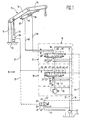
- FIG. J shows a hydraulic overload protection device for a loading crane in a simplified representation
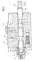
- FIG. 2 shows a longitudinal section through a directional control valve used in FIG. 1
- FIG. 3 shows a partial section through another embodiment of the directional control valve for controlling the overload protection device according to FIG. J.
- FIG. 1 shows a hydraulic overload protection device 10 for a loading crane, of which in simplified ter way a multi-section boom 11 is shown.
- the cantilever arm 11 consists of three cantilever arm parts, namely a crane column 13 arranged on a support frame 12, an inner arm 14 pivotably mounted on the crane column and an outer arm 15 pivotably mounted on the latter (14).
- the inner arm 14 is provided with a lifting cylinder 16 articulated on the support frame 12 can be raised and lowered, while the outer arm 15 is adjustable with the aid of a double-acting pivot cylinder 17 articulated between the two arms 14, 15.
- a hydraulic control device 18 which has a first directional valve 19 assigned to the lifting cylinder 16 and a second directional valve 21 assigned to the pivot cylinder 17.
- the first directional valve 19, which will be discussed in more detail below, has a control slide 22, which is centered by a double-acting return device 23 in a central position 24 and can be deflected to a lifting position 26 and a lowering position 27 by a manual actuation device 25 on both sides.
- the first directional valve 19 has an inlet connection 28, which is secured in a manner known per se by a check valve 29 and has an inlet line 31 with the outlet of a pump 32 » , which sucks pressure medium from a tank 33.
- a return connection 34 is relieved via a return line 35 to the tank 33.
- a motor connection 36 of the first directional valve 19, designated B, has a connection via a consumer line 37 to a pressure chamber 38 of the single-acting lifting cylinder 16. Furthermore, the control slide 22 of the first directional valve 19 is switched into a neutral circulation channel 39, which branches upstream from the first directional valve 19 from the feed line 31, from the control slide Can be influenced via 22 and is led to the return line 35.
- the control device 18 also has an adjustable, pressure-controlled safety valve 41, which is designed as a 3/2 switching valve.
- the safety valve 41 has an inlet 42 which is connected to the outlet of the pump 32 in parallel with the inlet line 31.
- An outlet 43 of the safety valve 41 is relieved via an outlet line 44 to the tank 33.
- a control line 46 leads via a throttle 47 into a control chamber 48 of the first directional valve 19.
- the safety valve has a control connection 49, which is connected to the pressure chamber 38 of the lifting cylinder via a control pressure line 51.
- the safety valve 41 relieves its working connection 45 to the tank 33 and blocks the inlet 42. If there is sufficient pressure in the control connection 49, it can be deflected into a switching position 53 in which the inlet 42 is connected to the working connection 45 and the outlet 43 is blocked becomes.
- a control connection 54 branches off from the control line 46 and is guided in a controllable manner via the control slide 22 of the first directional valve 19 and leads downstream of the latter to the return line 35. While this control connection 54 is open in the middle position 24 and in the lifting position 26, it is interrupted in the lower position 27.
- the second directional control valve 21 used to control the pivoting cylinder 17 differs from the first directional control valve 19 primarily in that it also doubles in accordance with the double-acting function of the pivoting cylinder 17 is designed to act pelt.
- the same components on the second directional valve 21 are provided with the same reference numerals as in the first directional valve 19, but with the index '.
- the motor connection 36 ′ denoted by B is connected via a first working line 55 to the annular piston rod space 56 in the pivot cylinder 17, while the associated cylinder space 57 in the pivoting cylinder 17 is connected via a second working line 58 to the motor connection 59 denoted A in the second directional control valve 21 has connection.
- the neutral circulation channel 39 is interrupted in both working positions 26 ', 27', the associated working connections being connected to one another by a parallel position or a cross position.
- the control of the control connection 54' is designed in the same way as in the control slide 22 for the single-acting function.
- FIG. 2 shows a longitudinal section through the first directional valve 19 according to FIG. 1 in a constructive embodiment.
- the same parts as in Figure 1 are also provided with the same reference numerals.
- the first directional valve 19 has a housing 61, in which the motor connection A is closed by a screw 62 in accordance with the single-acting function.
- On the housing 61 on the side opposite the manual control 25, a housing cover 63 is fitted close to the housing 61. Together with the housing 61, this housing cover 63 delimits the control chamber 48 into which the control slide 22 projects with its outer piston section 64.
- the double-acting return device 23 for the control slide 22 is also arranged in the control chamber 48.
- the throttle 47 upstream of the control chamber 48 is arranged in the housing cover 63.
- the control chamber 48 is in the housing 61 only by a web 65 of a return chamber 66 separated, whereby the control connection 54 is formed in the first directional valve 19.
- a control edge 68 is formed on the outer piston section 64 by a flattened area 67, which opens or closes this control connection 54 as a function of the position of the control slide 22, as shown in FIG. 1 in more detail.
- the pressure in the pressure chamber 38 of the lifting cylinder 16, which is decisive for the load torque limitation, is set at the safety valve 41 to a predetermined, permissible maximum value. As long as this pressure value is not exceeded, the safety valve 41 is in its spring-centered basic position 52, whereby the control line 46 to the tank 33 is relieved. At the same time, input 42 is blocked.
- the pressure medium delivered by the pump 32 can flow to the return line 35 and back to the tank 33 via the neutral circulation channel 39 which is open in the respective middle positions 24, 24 '.
- the control slide 22 is brought into its raised position 26 in the first directional valve 19, while it is deflected into its lower position 27 to lower the inner arm 14.
- the outer arm 15 can be pivoted using the second directional valve 21. By deflecting in the lifting position 26 ', pressure medium flows into the cylinder space 57 and lifts the load hook. Conversely, the outer arm 15 is lowered in the lower position 27 '.
- control slide 22 is in a lower position 27 which increases the load moment on the extension arm 11, the control edge 68 of the control slide 22 pressed into the housing 61 interrupting the control connection 54.
- the pressure prevailing in the control line 46 builds up via the throttle 47 in the control chamber 48 and acts there on the full end face of the control spool 22. Since this pressure area is relatively large, a relatively weak pressure in the control chamber 48 is also sufficient for the Push control spool 22 back out of its lower position 27 into the central position 24, after which the control edge 68 opens the control connection 54.
- the pressure prevailing in the control chamber 48 to the tank 33 can be reduced since the cross section which is opened there is greater than the free flow cross section of the throttle 47.
- the control slide 22 therefore remains centered in its central position, the control edge 68 functioning in the manner of a hydraulic stop . Due to the relatively large end face of the piston section 64, a pressure level is sufficient to reset the control slide 22 of a few bar, as is already caused by the neutral circulation channel 39 in the hydraulic control device 18.
- control slide 22 If the control slide 22 is in the middle direction 24 in the first directional control valve 19, it cannot be brought back into a lowering position 27 which increases the load torque by an operator with the aid of the manual actuation device 25, as long as the load torque limit is exceeded, since a load building up again in the control chamber 48 Back pressure would prevent such a tax movement.
- the cantilever arm 11 cannot carry out any movements that increase the load moment, in particular the inner arm 14 and the outer arm 15 are further reduced from the position shown in FIG. 1 can. Conversely, movements of the cantilever arm 11 that reduce the load torque can still be controlled.
- the control slide 22 in the directional control valve 19 can be brought into its raised position 26 in order to pivot the inner arm 14 counterclockwise.
- the control slide 22 ' can be adjusted into its raised position 26' in order to pivot the outer arm 15 in the same direction of rotation, the load torque being reduced.
- FIG. 3 shows a partial longitudinal section through a third directional valve 70, which differs from that according to FIG. 2 as follows, the same reference numerals being used for the same parts.
- the third directional control valve 70 has another control spool 71, on which two additional control edges 72 for controlling the motor connection 59 denoted by A and an additional control edge 73 for controlling the neutral circulation channel 39 are arranged in accordance with the double-acting function of the directional control valve 70. Above all, however, the control edge 74 assigned to the control connection 54 is now arranged on the control slide 71 such that it blocks the assigned control connection 54 in the center position of the control slide 71 shown.
- the hydraulic stop is designed by the control edge 74 so that a control slide 71 pushed into the housing is moved with an responding safety valve 41 by the pressure building up in the control chamber 48 from the pressed working position beyond its central position to its drawn working position , after which the control edge 74 unloads the control chamber 48 to the return chamber 66.
- a load torque-increasing movement on the cantilever arm 11 is converted directly into a load torque-reducing movement.
Landscapes
- Engineering & Computer Science (AREA)
- Mechanical Engineering (AREA)
- Fluid-Pressure Circuits (AREA)
- Control And Safety Of Cranes (AREA)
Applications Claiming Priority (2)
| Application Number | Priority Date | Filing Date | Title |
|---|---|---|---|
| DE3414182 | 1984-04-14 | ||
| DE19843414182 DE3414182A1 (de) | 1984-04-14 | 1984-04-14 | Hydraulische ueberlastungsschutzvorrichtung fuer ein hebezeug |
Publications (2)
| Publication Number | Publication Date |
|---|---|
| EP0158740A2 true EP0158740A2 (fr) | 1985-10-23 |
| EP0158740A3 EP0158740A3 (fr) | 1988-10-19 |
Family
ID=6233616
Family Applications (1)
| Application Number | Title | Priority Date | Filing Date |
|---|---|---|---|
| EP84116265A Withdrawn EP0158740A3 (fr) | 1984-04-14 | 1984-12-22 | Dispositif hydraulique de protection contre les surcharges pour un appareil de levage |
Country Status (2)
| Country | Link |
|---|---|
| EP (1) | EP0158740A3 (fr) |
| DE (1) | DE3414182A1 (fr) |
Family Cites Families (3)
| Publication number | Priority date | Publication date | Assignee | Title |
|---|---|---|---|---|
| SE346762C (sv) * | 1970-11-04 | 1979-05-14 | Hiab Foco Ab | Sperr- och sekerhetsanordning vid hydrauliskt drivna kranar av vippkrantyp |
| DK131618B (da) * | 1973-01-26 | 1975-08-11 | Hojbjerg Maskinfabrik As | Kran, navnlig lastvognskran med en lastmomentbegrænsende styreindretning. |
| AT368107B (de) * | 1980-12-23 | 1982-09-10 | Palfinger Fa | Ladekran |
-
1984
- 1984-04-14 DE DE19843414182 patent/DE3414182A1/de not_active Withdrawn
- 1984-12-22 EP EP84116265A patent/EP0158740A3/fr not_active Withdrawn
Also Published As
| Publication number | Publication date |
|---|---|
| EP0158740A3 (fr) | 1988-10-19 |
| DE3414182A1 (de) | 1985-10-24 |
Similar Documents
| Publication | Publication Date | Title |
|---|---|---|
| DE2352742C2 (de) | Hydraulisches Senkbrems-Sperrventil | |
| DE69105851T2 (de) | Einrichtung zur Steuerung hydraulischer Motoren. | |
| DE10004905C2 (de) | Verfahren und Vorrichtung zur Steuerung eines Hubzylinders insbesondere von Arbeitsmaschinen | |
| DE2335704C2 (de) | Hydraulische Vorrangsteuereinrichtung für mindestens zwei Servomotoren | |
| DE1751934B2 (de) | Mit einem Stromteiler ausgestattetes Steuerventil für Flüssigkeitsmotoren | |
| DE2343832C3 (de) | Lästertassungs- und Druckbegrenzungsvorrichtung für druckmittelbetriebene Arbeitsgeräte | |
| DE3621854C2 (fr) | ||
| DE3237103C3 (de) | Sicherheitsventil als Lasthalteventil in der Hebezeughydraulik | |
| EP0505977B1 (fr) | Système de contrôle de vitesse pour entraînements hydrauliques de préférence pour vérins hydrauliques | |
| WO2000006915A1 (fr) | Circuit hydraulique | |
| EP0198119B1 (fr) | Distributeur hydraulique pour commande indépendamment de la charge | |
| EP0182100B1 (fr) | Dispositif de commande hydraulique | |
| DE10219718A1 (de) | Hydraulische Ventilanordnung | |
| WO1995033136A1 (fr) | Systeme de regulation d'un dispositif de levage avec soupape de regulation | |
| DE2307403A1 (de) | Ventilanordnung zur steuerung der betaetigung eines hydraulikmotors mit reversierender positiver verschiebung | |
| DE3025949C2 (fr) | ||
| EP0158740A2 (fr) | Dispositif hydraulique de protection contre les surcharges pour un appareil de levage | |
| DE19724432C1 (de) | Hydraulischer Steuerblock für Teleskopzylinder von Kippfahrzeugen oder ähnlichen Vorrichtungen | |
| DE3346999C2 (de) | Bremsanlage für einen über einen Antrieb bewegbaren Teil | |
| DE102013207299A1 (de) | Hydraulisches Wegeventil für das Hubwerk eines landwirtschaftlichen Fahrzeugs | |
| DE2740991B2 (de) | Hydrodynamisches Wendegetriebe | |
| EP0158738A2 (fr) | Dispositif hydraulique de protection contre les surcharges pour une grue de chargement | |
| EP0491155A1 (fr) | Distributeur pour commande d'un moteur hydraulique | |
| DE1506487B1 (de) | Einrichtung zur selbsttaetigen Begrenzung der Belastung von druckmittelbetaetigten Antriebselementen eines Kranes od.dgl. | |
| EP0624732A1 (fr) | Dispositif de commande hydraulique |
Legal Events
| Date | Code | Title | Description |
|---|---|---|---|
| PUAI | Public reference made under article 153(3) epc to a published international application that has entered the european phase |
Free format text: ORIGINAL CODE: 0009012 |
|
| 17P | Request for examination filed |
Effective date: 19841222 |
|
| AK | Designated contracting states |
Designated state(s): DE FR GB IT |
|
| PUAL | Search report despatched |
Free format text: ORIGINAL CODE: 0009013 |
|
| AK | Designated contracting states |
Kind code of ref document: A3 Designated state(s): DE FR GB IT |
|
| STAA | Information on the status of an ep patent application or granted ep patent |
Free format text: STATUS: THE APPLICATION HAS BEEN WITHDRAWN |
|
| 18W | Application withdrawn |
Withdrawal date: 19881221 |
|
| RIN1 | Information on inventor provided before grant (corrected) |
Inventor name: KOETTER, WOLFGANG, DIPL.-ING. |