EP0159072A1 - Phasenkomparator mit linearer Wirkungsweise und einen solchen Phasenkomparator enthaltende Phasenriegelschleife - Google Patents
Phasenkomparator mit linearer Wirkungsweise und einen solchen Phasenkomparator enthaltende Phasenriegelschleife Download PDFInfo
- Publication number
- EP0159072A1 EP0159072A1 EP85200446A EP85200446A EP0159072A1 EP 0159072 A1 EP0159072 A1 EP 0159072A1 EP 85200446 A EP85200446 A EP 85200446A EP 85200446 A EP85200446 A EP 85200446A EP 0159072 A1 EP0159072 A1 EP 0159072A1
- Authority
- EP
- European Patent Office
- Prior art keywords
- comparator
- phase
- loop
- output
- input
- Prior art date
- Legal status (The legal status is an assumption and is not a legal conclusion. Google has not performed a legal analysis and makes no representation as to the accuracy of the status listed.)
- Granted
Links
- 230000009467 reduction Effects 0.000 claims abstract description 12
- 230000006870 function Effects 0.000 claims description 8
- 230000003111 delayed effect Effects 0.000 claims description 5
- 238000005070 sampling Methods 0.000 claims description 5
- 238000001914 filtration Methods 0.000 claims description 2
- 238000005259 measurement Methods 0.000 description 3
- 230000010363 phase shift Effects 0.000 description 3
- 238000009825 accumulation Methods 0.000 description 2
- 230000007423 decrease Effects 0.000 description 2
- 230000015654 memory Effects 0.000 description 2
- 230000009471 action Effects 0.000 description 1
- 230000015556 catabolic process Effects 0.000 description 1
- 230000009849 deactivation Effects 0.000 description 1
- 238000006731 degradation reaction Methods 0.000 description 1
- 230000001934 delay Effects 0.000 description 1
- 230000000694 effects Effects 0.000 description 1
- 230000007774 longterm Effects 0.000 description 1
- 238000000034 method Methods 0.000 description 1
- 230000008569 process Effects 0.000 description 1
- 238000011144 upstream manufacturing Methods 0.000 description 1
Images
Classifications
-
- H—ELECTRICITY
- H03—ELECTRONIC CIRCUITRY
- H03L—AUTOMATIC CONTROL, STARTING, SYNCHRONISATION OR STABILISATION OF GENERATORS OF ELECTRONIC OSCILLATIONS OR PULSES
- H03L7/00—Automatic control of frequency or phase; Synchronisation
Definitions
- the present invention relates to a phase comparator with linearized operation, as well as a phase locked loop comprising such a phase comparator.
- US patent US-A-3997848 describes a demodulator composed in particular of a phase locked loop whose phase comparator has a linearized operation using an auxiliary loop. But the effect of this is to reduce the modulation index of a modulator present upstream of one of the comparator inputs (the main loop input), and not to modify, as in the case of the invention, the dynamics of the comparator without intervening on the input signal of the comparator, using an auxiliary loop which may furthermore be composed only of passive elements.
- a first aim of the invention is therefore to propose a phase comparator, the operation of which is also linearized but by other means.
- the phase comparator according to the invention is characterized in that it is associated with an auxiliary loop called dynamic reduction composed on the one hand of means for reducing a determined value of the phase difference between the two inputs of the comparator and, on the other hand, means for restoring said value at the output of the comparator by means of delaying the information expressing this value.
- the result is less affected by the non-linearities of the comparator (for example, for comparators with sinusoidal characteristic, the distortion is d 'as much smaller as the phase shift to be measured is lower, since the approximation of sin ⁇ by ⁇ is all the better as ⁇ is weaker).
- Another object of the invention is to provide a phase locked loop comprising a phase comparator with linearized operation. Indeed, beyond a certain phase difference value, the comparator can no longer measure this difference precisely because of the non-linearities of its transfer function. This results in a degradation of the performance of the loop, which may even fail to lock onto the input signal.
- the loop according to the invention which traditionally comprises a phase comparator, a loop filter and an oscillator, respectively for measuring the phase difference between an input signal on LequeL must occur said locking and the output signal from the oscillator, to transmit to the oscillator said phase difference by filtering it, and to deliver to the phase comparator a signal whose frequency is corrected in the direction of a decrease in said phase difference, is then characterized in that it is associated with a dilute dynamic reduction auxiliary loop composed on the one hand of means for reducing a determined value of the phase difference between the two comparator inputs and on the other hand of restitution means of said value at the output of the comparator by means of delaying the information expressing this value.
- the accuracy of the measurement of the phase difference operated by the comparator inside the loop is improved, since, by means of the provisional reduction (by a known quantity) of the quantity to be measured, said measurement is carried out in the Linear region of the comparator characteristic.
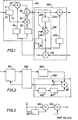
- the phase comparator 100 shown in a particular embodiment in FIG. 1 here comprises a quadrature filter 10 which receives the input signal and delivers this delayed input signal to an output 11, the phase of which is denoted ⁇ E , and on an output 12 this same delayed signal but phase shifted by ⁇ / 2 and whose phase is therefore noted ⁇ E + ⁇ / 2.
- the outputs 11 and 12 are connected to the first respective inputs of two multipliers 20 and 30, the second inputs of which receive the respective outputs of two read-only memories 40 and 50 whose addressing is common and which are directly controlled Dar Le siqnal to which will be compared
- the phase signal ⁇ E is a quadrature filter 10 which receives the input signal and delivers this delayed input signal to an output 11, the phase of which is denoted ⁇ E , and on an output 12 this same delayed signal but phase shifted by ⁇ / 2 and whose phase is therefore noted ⁇ E + ⁇ / 2.
- the outputs 11 and 12 are connected to the first respective inputs of two multipliers
- This comparator 100 is associated with an auxiliary stage 200, called an auxiliary dynamic reduction loop and composed on the one hand of an adder 210 receiving inputs ⁇ S and ⁇ O and transmitting the sum ( ⁇ S + ⁇ O to comparator 100 ), on the other hand of an adder 220 receiving the output of comparator 100 and adding thereto The input ⁇ O of the adder 210 delayed by a delay circuit 230, and finally of a circuit 240 generating the signal ⁇ O supplied directly to the adder 210 and via the circuit 230 to the adder 220.
- This circuit 240 comprises a summer 241 receiving on a first positive input directly the output of the comparator 100, on a second negative input this same output of the comparator 100 but after crossing a filter 242, and on a third positive input its own output ⁇ O but delayed by a delay circuit 243.
- the phase comparator then delivers information which, instead of being of the sin type ( ⁇ E - ⁇ S ), is of the sin type (O E - ⁇ S - ⁇ O ). To restore the accuracy of the result provided by the comparator 100, it then only remains to add the information ⁇ O which had artificially reduced the phase difference to be measured.
- the comparator thus proposed may in particular be introduced into a phase-locked loop, for example of the digital type, such as that shown in FIG. 2.
- This digital loop here comprises the comparator 100, the auxiliary stage 200, a loop filter 300 and a digitally controlled oscillator 400.
- Comparator 100 measures the phase difference existing between the phase input signal ⁇ E on Lequet must lock The loop and The phase signal ( ⁇ S + ⁇ O ) supplied on its other input.
- the loop filter 300 transmits to the oscillator 400 the phase difference obtained at the output of the comparator 100 and corrected by action of the stage 200.
- the signal thus transmitted to the oscillator 400 modifies the frequency of the latter so that The phase difference decreases, this process ensuring the locking of the loop on the phase signal ⁇ E.
- Comparator 100 and Stage 200 include the same elements as above.
- the loop filter 300 is a low pass filter.
- the oscillator 400 is of the accumulator type and comprises an adder 401 receiving on its first input its own output after passing through a delay circuit 402 and a filter 403 identical to the loop filter 300, on a second input The output loop filter 300, and on a third input an accumulation constant ⁇ P representing the phase increment.
- the delays caused by the delay circuits 243 and 402 are equal to an integer number of sampling periods, generally one period.
- a phase locked loop having this structure has better performance in terms of stability, precision, speed and frequency band than those obtained with the same loop not equipped with the auxiliary stage 200.
- the linearization of the operation of the comparator allows this loop to work practically in the whole Nyquist band (excluding the zero frequency, the half frequency of sampling and frequencies near these two frequencies).
- such a loop used in a frequency demodulator, has a threshold extension often greater than that obtained with analog phase locked loops; indeed, while in analog the minimum value of the loop gain is limited by the long-term drifts of the components, for a digital loop this gain can take the optimal value 1 (that is to say, The loop being open, a continuous phase shift ⁇ at its input causes a continuous phase shift - ⁇ at the output of the oscillator).
- the present invention is not limited to the exemplary embodiments described and shown from which variants can be proposed without thereby departing from the scope of the invention.
- the loop filter is a digital filter, and that this filter, or even the entire loop, can, if the sampling frequency is not too high, be replaced by a microprocessor performing the same functions.
- phase difference value obtained at the output of comparator 100 is minimal when The transfer function of the auxiliary filter 242 is equal to that of the loop, in closed loop, and that the delay provided by the delay circuit 230 is limited to a sampling period.
- this transfer function of the filter 242 may not be than an approximation of that cited above, and the delay brought by the circuit 230 can be greater than a period.
- the loop filter 300, the filter 242 and the filter 403 are preferably chosen to have a transfer function identical and equal to that of the deactivation filter defined in the SECAM coding, but these transfer functions of the filter 403 may each be only an approximation of that desired.
- the de-emphasized color difference signal is obtained after passing through a filter shown in FIG.
- the output of the first subtractor 502 gives the phase difference between two generally successive samples of the oscillator output signal
- the second subtractor 503 subtracts from this difference the accumulation constant ⁇ P , which here represents the phase increment of the sub- color carrier between two successive samples, and thus delivers a signal proportional to the color difference signal.
Landscapes
- Stabilization Of Oscillater, Synchronisation, Frequency Synthesizers (AREA)
Applications Claiming Priority (2)
| Application Number | Priority Date | Filing Date | Title |
|---|---|---|---|
| FR8405024A FR2562351B1 (fr) | 1984-03-30 | 1984-03-30 | Comparateur de phase a fonctionnement linearise et boucle a verrouillage de phase comprenant un tel comparateur de phase |
| FR8405024 | 1984-03-30 |
Publications (2)
| Publication Number | Publication Date |
|---|---|
| EP0159072A1 true EP0159072A1 (de) | 1985-10-23 |
| EP0159072B1 EP0159072B1 (de) | 1989-06-07 |
Family
ID=9302645
Family Applications (1)
| Application Number | Title | Priority Date | Filing Date |
|---|---|---|---|
| EP85200446A Expired EP0159072B1 (de) | 1984-03-30 | 1985-03-25 | Phasenkomparator mit linearer Wirkungsweise und einen solchen Phasenkomparator enthaltende Phasenriegelschleife |
Country Status (5)
| Country | Link |
|---|---|
| US (1) | US4607236A (de) |
| EP (1) | EP0159072B1 (de) |
| JP (1) | JPS60220626A (de) |
| DE (1) | DE3570964D1 (de) |
| FR (1) | FR2562351B1 (de) |
Families Citing this family (4)
| Publication number | Priority date | Publication date | Assignee | Title |
|---|---|---|---|---|
| US4962428A (en) * | 1989-04-20 | 1990-10-09 | Motorola, Inc. | Multistandard OSD in a TV receiver including display positioning |
| US4962427A (en) * | 1989-04-20 | 1990-10-09 | Motorola Inc. | TV receiver including multistandard OSD |
| JPH05308226A (ja) * | 1992-04-30 | 1993-11-19 | Sony Corp | 周波数変換回路 |
| US6275087B1 (en) * | 1999-11-16 | 2001-08-14 | Lsi Logic Corporation | Adaptive cancellation of time variant DC offset |
Citations (2)
| Publication number | Priority date | Publication date | Assignee | Title |
|---|---|---|---|---|
| DE1466080A1 (de) * | 1965-07-14 | 1969-07-03 | Fujitsu Ltd | Einrichtung zur automatischen Phasensteuerung |
| US4145663A (en) * | 1977-01-18 | 1979-03-20 | Tokyo Shibaura Electric Co., Ltd. | Digital synchronous detectors using time division for extracting carrier wave and demodulated signals |
Family Cites Families (4)
| Publication number | Priority date | Publication date | Assignee | Title |
|---|---|---|---|---|
| US3997848A (en) * | 1975-11-26 | 1976-12-14 | The United States Of America As Represented By The Administrator Of The National Aeronautics And Space Administration | Linear phase demodulator including a phase locked loop with auxiliary feedback loop |
| FR2419614A1 (fr) * | 1978-03-10 | 1979-10-05 | Cit Alcatel | Circuit de recuperation de la porteuse d'un signal numerique synchrone transmis par modulation d'amplitude |
| US4378509A (en) * | 1980-07-10 | 1983-03-29 | Motorola, Inc. | Linearized digital phase and frequency detector |
| US4418318A (en) * | 1981-03-10 | 1983-11-29 | Frederick Electronics Corporation | Digital phase-locked loop circuit |
-
1984
- 1984-03-30 FR FR8405024A patent/FR2562351B1/fr not_active Expired
-
1985
- 1985-03-25 EP EP85200446A patent/EP0159072B1/de not_active Expired
- 1985-03-25 DE DE8585200446T patent/DE3570964D1/de not_active Expired
- 1985-03-25 US US06/715,423 patent/US4607236A/en not_active Expired - Fee Related
- 1985-03-28 JP JP60062187A patent/JPS60220626A/ja active Pending
Patent Citations (2)
| Publication number | Priority date | Publication date | Assignee | Title |
|---|---|---|---|---|
| DE1466080A1 (de) * | 1965-07-14 | 1969-07-03 | Fujitsu Ltd | Einrichtung zur automatischen Phasensteuerung |
| US4145663A (en) * | 1977-01-18 | 1979-03-20 | Tokyo Shibaura Electric Co., Ltd. | Digital synchronous detectors using time division for extracting carrier wave and demodulated signals |
Non-Patent Citations (1)
| Title |
|---|
| PROCEEDINGS OF THE SYMPOSIUM ON COMPUTER PROCESSING IN COMMUNICATIONS, New York, 8-10 avril 1969, pages 343-357, Polytechnic Press, Brooklyn, N.Y., US; W.E. LARIMORE: "Design and performance of a second order digital phase-locked loop" * |
Also Published As
| Publication number | Publication date |
|---|---|
| JPS60220626A (ja) | 1985-11-05 |
| FR2562351A1 (fr) | 1985-10-04 |
| DE3570964D1 (en) | 1989-07-13 |
| US4607236A (en) | 1986-08-19 |
| EP0159072B1 (de) | 1989-06-07 |
| FR2562351B1 (fr) | 1986-06-20 |
Similar Documents
| Publication | Publication Date | Title |
|---|---|---|
| US5619536A (en) | Digital superheterodyne receiver and baseband filter method used therein | |
| EP1331729A1 (de) | Vorverzerrungskompensierter linearer Verstärker | |
| US20080129572A1 (en) | A/d-converter | |
| WO2015082233A1 (fr) | Procédé et dispositif de compensation du désappariement de bandes passantes de plusieurs convertisseurs analogiques/numériques temporellement entrelacés | |
| FR2718910A1 (fr) | Dispositif de décision à seuils adaptatifs pour modulation à multiétat. | |
| FR2490427A1 (fr) | Demodulateur d'un signal module en frequence et systeme de television comportant un tel demodulateur | |
| EP0238141A1 (de) | Empfänger für frequenzmodulierte Signale | |
| EP0159072B1 (de) | Phasenkomparator mit linearer Wirkungsweise und einen solchen Phasenkomparator enthaltende Phasenriegelschleife | |
| EP3624343B1 (de) | Regulierungsvorrichtung der sperrung eines frequenzmultiplikators mit injektionssperre | |
| EP0635946B1 (de) | AD-Wandler mit modulierten Rückkopplungsschleife | |
| EP0506501B1 (de) | Phasenkomparator mit grossem Dynamikbereich | |
| EP0744095B1 (de) | Einrichtung zur kontinuierlichen phasenmodulation mit frequenzsynthetisierer mit phasenregelscheife | |
| EP0150880A2 (de) | Demodulator mit phasenverkettetem Kreis | |
| EP1782536B1 (de) | Verfahren zum erzeugen eines digitalsignals, das anpassungsfehler in einem analog/digital-umsetzungssystem mit zeitverschachtelung repräsentiert und analog/digital-umsetzer mit zeitverschachtelung damit | |
| EP0068571A1 (de) | Digitale Demodulationsschaltung für ein frequenzmoduliertes Signal, Anwendung dieser Schaltung zur Verwirklichung einer Demodulationsstufe für das Chrominanzsignal eines Fernsehempfängers und Fernsehempfänger mit einer solchen Stufe | |
| EP0702453A1 (de) | Schaltung zur automatischen Verstärkungsregelung und Vorrichtung mit einer solchen Schaltung | |
| CA2106268A1 (fr) | Circuit de codage analogique-numerique a compensation automatique du decalage du zero | |
| EP0116990B1 (de) | Einrichtung zur selbstabgleichenden Amplitudenentzerrung für digitale Richtfunkstrecken | |
| FR2938082A1 (fr) | Procede de controle du retard de boucle dans un modulateur sigma-delta et modulateur mettant en oeuvre le procede | |
| CA2347164A1 (fr) | Compensation du retard du convertisseur analogique-numerique dans les modulateurs sigma-delta | |
| FR3127661A1 (fr) | Convertisseur temps numérique et boucle à verrouillage de phase | |
| EP1421683A2 (de) | System zur verstärkung eines hochfrequenzsignals und dekodierer für fernsehsignale mit einem solchen system | |
| WO2023072906A1 (fr) | Numériseur radiofréquence à dynamique augmentée | |
| WO2003096644A1 (fr) | Generateur d'un signal radiofrequence comprenant des composantes de modulation d'amplitude et de phase ou frequence synchronisees | |
| FR2864737A1 (fr) | Modulateur rf numerique comprenant une voie de retour en phase ou frequence |
Legal Events
| Date | Code | Title | Description |
|---|---|---|---|
| PUAI | Public reference made under article 153(3) epc to a published international application that has entered the european phase |
Free format text: ORIGINAL CODE: 0009012 |
|
| AK | Designated contracting states |
Designated state(s): DE FR GB |
|
| 17P | Request for examination filed |
Effective date: 19860416 |
|
| 17Q | First examination report despatched |
Effective date: 19871127 |
|
| GRAA | (expected) grant |
Free format text: ORIGINAL CODE: 0009210 |
|
| AK | Designated contracting states |
Kind code of ref document: B1 Designated state(s): DE FR GB |
|
| REF | Corresponds to: |
Ref document number: 3570964 Country of ref document: DE Date of ref document: 19890713 |
|
| GBT | Gb: translation of ep patent filed (gb section 77(6)(a)/1977) | ||
| REG | Reference to a national code |
Ref country code: FR Ref legal event code: CD |
|
| PLBE | No opposition filed within time limit |
Free format text: ORIGINAL CODE: 0009261 |
|
| STAA | Information on the status of an ep patent application or granted ep patent |
Free format text: STATUS: NO OPPOSITION FILED WITHIN TIME LIMIT |
|
| 26N | No opposition filed | ||
| REG | Reference to a national code |
Ref country code: FR Ref legal event code: CJ Ref country code: FR Ref legal event code: CD |
|
| PGFP | Annual fee paid to national office [announced via postgrant information from national office to epo] |
Ref country code: GB Payment date: 19960229 Year of fee payment: 12 |
|
| PGFP | Annual fee paid to national office [announced via postgrant information from national office to epo] |
Ref country code: FR Payment date: 19960327 Year of fee payment: 12 |
|
| PGFP | Annual fee paid to national office [announced via postgrant information from national office to epo] |
Ref country code: DE Payment date: 19960523 Year of fee payment: 12 |
|
| PG25 | Lapsed in a contracting state [announced via postgrant information from national office to epo] |
Ref country code: GB Effective date: 19970325 |
|
| GBPC | Gb: european patent ceased through non-payment of renewal fee |
Effective date: 19970325 |
|
| PG25 | Lapsed in a contracting state [announced via postgrant information from national office to epo] |
Ref country code: FR Free format text: LAPSE BECAUSE OF NON-PAYMENT OF DUE FEES Effective date: 19971128 |
|
| PG25 | Lapsed in a contracting state [announced via postgrant information from national office to epo] |
Ref country code: DE Effective date: 19971202 |
|
| REG | Reference to a national code |
Ref country code: FR Ref legal event code: ST |