EP0159078B1 - Vorrichtung zur Stromentnahme an einer Spannungsschiene - Google Patents
Vorrichtung zur Stromentnahme an einer Spannungsschiene Download PDFInfo
- Publication number
- EP0159078B1 EP0159078B1 EP85200476A EP85200476A EP0159078B1 EP 0159078 B1 EP0159078 B1 EP 0159078B1 EP 85200476 A EP85200476 A EP 85200476A EP 85200476 A EP85200476 A EP 85200476A EP 0159078 B1 EP0159078 B1 EP 0159078B1
- Authority
- EP
- European Patent Office
- Prior art keywords
- housing
- rail
- carriage
- contact members
- pressed
- Prior art date
- Legal status (The legal status is an assumption and is not a legal conclusion. Google has not performed a legal analysis and makes no representation as to the accuracy of the status listed.)
- Expired
Links
- 239000004020 conductor Substances 0.000 claims abstract description 28
- 230000008878 coupling Effects 0.000 claims abstract description 18
- 238000010168 coupling process Methods 0.000 claims abstract description 18
- 238000005859 coupling reaction Methods 0.000 claims abstract description 18
- 229920002994 synthetic fiber Polymers 0.000 claims abstract description 9
- 210000002105 tongue Anatomy 0.000 claims description 11
- 239000000463 material Substances 0.000 claims description 2
- 238000010276 construction Methods 0.000 description 3
- RYGMFSIKBFXOCR-UHFFFAOYSA-N Copper Chemical compound [Cu] RYGMFSIKBFXOCR-UHFFFAOYSA-N 0.000 description 2
- 239000010949 copper Substances 0.000 description 2
- 229910052802 copper Inorganic materials 0.000 description 2
- 238000007689 inspection Methods 0.000 description 2
- 239000004411 aluminium Substances 0.000 description 1
- XAGFODPZIPBFFR-UHFFFAOYSA-N aluminium Chemical compound [Al] XAGFODPZIPBFFR-UHFFFAOYSA-N 0.000 description 1
- 229910052782 aluminium Inorganic materials 0.000 description 1
- 210000005069 ears Anatomy 0.000 description 1
- 238000011065 in-situ storage Methods 0.000 description 1
- 230000037431 insertion Effects 0.000 description 1
- 238000003780 insertion Methods 0.000 description 1
Images

Classifications
-
- H—ELECTRICITY
- H01—ELECTRIC ELEMENTS
- H01R—ELECTRICALLY-CONDUCTIVE CONNECTIONS; STRUCTURAL ASSOCIATIONS OF A PLURALITY OF MUTUALLY-INSULATED ELECTRICAL CONNECTING ELEMENTS; COUPLING DEVICES; CURRENT COLLECTORS
- H01R25/00—Coupling parts adapted for simultaneous co-operation with two or more identical counterparts, e.g. for distributing energy to two or more circuits
- H01R25/14—Rails or bus-bars constructed so that the counterparts can be connected thereto at any point along their length
- H01R25/142—Their counterparts
Definitions
- the invention relates to a current collector device intended to be connected to a voltage rail comprising a bottom part with two parallel side walls, on whose inner side are provided longitudinally extending ribs, at least two mutually insulated current conductors being present on the bottom part, which current collector device comprises a housing of synthetic material, and is provided with projecting contact members and is shaped so that it can be pressed into the voltage-rail, an electrical connection being formed between the contact members and the current conductors, while this housing is further detachably secured to the side walls of the voltage rail by means of engagement between parts of the housing and ribs in the rail.
- Such a current collector device is known from NL-A-7113699.
- Said known current collector device comprises a detachable housing to be clamped in a cable channel for forming a connection between, for example, a cable secured to the housing and electrical conductors disposed in the cable channel.
- the cable channel is in the form of a rail comprising a bottom part with mutually insulated current conductors and two parallel profiled side walls on either side thereof.
- the electrical connection between the contact members secured to the housing and the current conductors is established by a pressure contact.
- the side wall of the housing is provided with locking cams cooperating with ribs in the rail, the locking effect being obtained in that during insertion the side wall of the housing is pressed inwards.
- a number of wedge-shaped recesses are provided in the side wall.
- the invention has for its object to provide a current collector device, whose housing is constructed so that the aforementioned disadvantages, which are inherent in the known device, are avoided.
- a current collector device of the kind mentioned in the opening paragraph is characterized in that the housing accommodates a carriage which carries the contact members and which is slidable in longitudinally extending guiding means between two abutments in the housing, the first abutment defining a decoupling position, in which the housing can be pressed into the rail, and the second abutment defining a coupling position, in which the housing is locked in the rail in the pressed-in state.
- the housing of the device according to the invention comprises only a small number of components, is of rigid construction, can be assembled in a comparatively simple manner and can be readily manipulated by a user.
- the housing can be readily pressed into the space of the rail enclosed by the side walls and the bottom part of the rail, the carriage then occupying the decoupling position.
- the contact members form a pressure connection (preferably with a certain amount of resilientforce) with the current conductors, which are located on the bottom part of the rail.
- the housing is mechanically locked in its position on the rail, after which the carriage need be moved only in the longitudinal direction of the rail by the user until the carriage reaches its coupling position.
- the contact members secured to the carriage which may be blade shaped, and then moved over the surface of the respective current conductors. As a result, a good electrical contact between the said members and the current conductors is ensured when the carriage is adjusted to the coupling position.
- a current collector device intended to be connected to a voltage rail, which device is coupled to said rail with help of its current contact members.
- the free ends of said members are somewhat curved-shaped, said ends being fixed behind the current conductors in the rail by means of a wedge-shaped member.
- said device is secured to the rail by means of the electrical connection members.
- GB-A-1.346.831 a device for coupling two voltage rails is described.
- the electrical conductor elements in the coupler are provided with ears including inwardly towards each other for the realization of the mechanical and electrical coupling.
- No slidable carriage provided with projecting contact members is present in such a device.
- the locking on the voltage rail in the device according to the invention is preferably obtained in that the housing is provided with resilient tongues which are located on either side of the carriage and which on the one hand are adapted to cooperate with the ribs on the inner side of the side walls of the rail and on the other hand cooperate with cams on the carriage.
- the housing is provided with upright walls which are located on either side of the carriage and guide the carriage with their inner side and on their outer side area accurately fitting with the side walls of the rail when the housing is pressed in the rail.
- This embodiment has the advantage that not only correct positioning of the carriage with respect to the housing is obtained, but that due to the upright walls a good guidance is also obtained when the housing is placed on and pressed into the rail.
- the current collector device according to the invention is connected in a practical embodiment to a luminaire.
- This connection is preferably detachable.
- a detachable connection between a housing of synthetic material and a luminaire is described, for example, in NL-A-8104430 laid open to public inspection.
- the construction described in this Patent Application can advantageously be used in the device according to the invention.
- the housing of the device is provided for this purpose on its side remote from the carriage with a collar, which encloses a cylindrical cavity in which are disposed current supply conductors which are electrically connected to the contact members and which are situated on the lower side of two coaxially arranged sleeves of electrically insulative material for receiving plug-in contact members of a tubular wall portion of a luminaire cooperating with the current supply members.
- a preferred embodiment of the device according to the invention is characterized in that the sleeves and the carriage form an integral unit, while, when the carriage is adjusted to the coupling position, the centre line of the sleeve coincides with the centre line of the cylindrical cavity and the sleeves occupy an asymmetrical position with respect to the centre line of the cavity in the decoupling position of the carriage.
- An advantage of this embodiment is that the luminaire cannot be secured on the housing of the device until the housing is locked on the rail.
- the luminaire When the luminaire is secured in the housing, movement of the carriage is prevented, so that it is not possible to remove the housing with the luminaire from the rail.
- the safety of such a device is improved because it prevents the housing of the device from being removed from the rail together with a luminaire coupled thereto and provided with a burning lamp.
- situations in which the fire risk is high are liable to occur near the rail in such cases.
- the housing serves as a coupling member for two voltage rails arranged in line with each other.
- the carriage is provided, for example, with a first set of contact members which cooperate with current conductors in the first rail and with a second set of contact members which are electrically connected to the first set (for example by means of conductors in the housing or in the carriage) and cooperate with current conductors in the second rail.
- first set of contact members which cooperate with current conductors in the first rail
- a second set of contact members which are electrically connected to the first set (for example by means of conductors in the housing or in the carriage) and cooperate with current conductors in the second rail.
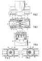
- A denotes a voltage rail which has a channel-shaped aluminium wall.
- the rail comprises a bottom part 1 with two parallel side walls 2 and 3. Longitudinally extending ribs 4 and 5 are provided on the inner side of the side walls. In the- proximity of the rib 4 is arranged a conductor 4a, which is intended to connect the voltage rail to earth.
- the bottom part 1 is further provided with an opening 12 to secure the rail to a wall or a ceiling.
- the letter B indicates a housing of electrically- insulative synthetic material of a current collector .device according to the invention.
- the housing is shaped so that it can be pressed into the opening formed by the side walls 2 and 3 of the rail.
- the housing is provided on the side facing the rail with a carriage 13 which carries the blade shaped contact members 14 and 15.
- a carriage 13 which carries the blade shaped contact members 14 and 15.
- the housing can be detachably secured in the rail by means of laterally projecting edges acting as latches present at its side cooperating with the ribs 4 and 5 present in the side wall of the rail. These edges are located on the outer side of four upright resilient tongues 16, 17, 18 and 19 located on either side of the carriage 13.
- the said edges for the tongues 16 and 17 are designated by reference numerals 20 and 21.
- the resilient tongues 16 to 19 also cooperate with cams on the carriage 13.
- two cams near the resilient tongue 16 are designated by reference numerals 22 and 23 (see also Fig. 3).
- the carriage is slidable between two extreme positions, i.e. a decoupling position and a coupling position.
- the cams (22, 23) substantially do not touch the resilient tongues (such as 16).
- this position is shown.
- a user moves the carriage 13 into the coupling position, i.e. the carriage shown in the drawing is pressed to the right until the cams 22 and 23 on the carriage are located opposite to cams (such as 24 and 25) on the inner wall of a tongue (such as 16).
- the tongues are then pressed slightly outwards in a manner such that, when inserted in the rail, the edges (such as 20, 21) located on the other side of the tongue are pressed behind the ribs 4 and 5 of the rail.
- the housing is then locked on the rail. The locked state is also visible in Fig. 4.
- the housing is further provided with two upright walls 26 and 27 which are located on either side of the carriage 13 and cooperate on their inner side with the carriage, which due to ribs in these walls is substantially constrained from sideways movement (see Fig. 2 and 3) while they cooperate on their outer side with the side walls of the rail when the housing is placed on the rail (for simplicity not shown in Fig. 4).
- the walls then accurately fit between the ribs 4 and 5.
- the walls 26 and 27 promote a good mechanical guidance when the housing is pressed into the rail.
- the carriage is slidable between two extreme positions, (the coupling position and the decoupling position.
- the carriage is provided on each side with an additional pair of cams (13a and 13b) which abut against a protuberance (such as 26a) on the inner side of the walls 26 and 27 (see Fig. 3).
- the housing On the side remote from the carriage, the housing is provided with a collar 28, which encloses a cylindrical cavity.
- the housing is then suitable to receive a tubular wall portion of a luminaire.
- a tubular wall portion of a luminaire For a further description of such a luminaire, reference is made to the aforementioned NL-A-8104430 laid open to public inspection.
- the tubular wall portion is provided with current supply conductors, which, when placed in the cavity within collar 28 of the housing of the current collector device, cooperate with current supply members located in the cavity.
- These current supply members are electrically connected by means of slightly resilient conductors to the knife-shaped contact members (14, 15) on the carriage 13 and are located on the lower side of two coaxially arranged cylindrical walls or sleeves 29, 30 (see Figures 5 and 6) of electrically insulative synthetic material, which form an integral unit with the carriage and merce into the cavity within the collar 28.
- a first current-conveying member is located on the lower side of the sleeve 29, while a second member is located on the lower side between the walls of the sleeves 29 and 30. The said current supply members then cannot be touched.
- the centre line 31 of the sleeves (29, 30) corresponds to the centre line of the cylindrical cavity within the collar 28.
- the luminaire having the wall portion projecting in the form of a tube can then be inserted into the cavity 28.
- the housing comprises only a small number of components. It can therefore be readily assembled.
- the knife-shaped contact members and the current supply members located on the lower side of the sleeves form an integral unit, the part located between the contact members and the current supply members being folded at one point.
- a resilient action of the contact members is obtained when provided in the rail.
- the use of separate components (such as springs, clamps and the like) is then avoided.
Landscapes
- Arrangement Of Elements, Cooling, Sealing, Or The Like Of Lighting Devices (AREA)
- Details Of Connecting Devices For Male And Female Coupling (AREA)
- Pharmaceuticals Containing Other Organic And Inorganic Compounds (AREA)
- Saccharide Compounds (AREA)
- Current-Collector Devices For Electrically Propelled Vehicles (AREA)
- Driving Mechanisms And Operating Circuits Of Arc-Extinguishing High-Tension Switches (AREA)
- Relay Circuits (AREA)
- Connector Housings Or Holding Contact Members (AREA)
Claims (5)
Priority Applications (1)
| Application Number | Priority Date | Filing Date | Title |
|---|---|---|---|
| AT85200476T ATE39794T1 (de) | 1984-04-02 | 1985-03-29 | Vorrichtung zur stromentnahme an einer spannungsschiene. |
Applications Claiming Priority (2)
| Application Number | Priority Date | Filing Date | Title |
|---|---|---|---|
| NL8401029A NL8401029A (nl) | 1984-04-02 | 1984-04-02 | Stroomafneeminrichting voor aansluiting op een spanningsrail. |
| NL8401029 | 1984-04-02 |
Publications (2)
| Publication Number | Publication Date |
|---|---|
| EP0159078A1 EP0159078A1 (de) | 1985-10-23 |
| EP0159078B1 true EP0159078B1 (de) | 1989-01-04 |
Family
ID=19843736
Family Applications (1)
| Application Number | Title | Priority Date | Filing Date |
|---|---|---|---|
| EP85200476A Expired EP0159078B1 (de) | 1984-04-02 | 1985-03-29 | Vorrichtung zur Stromentnahme an einer Spannungsschiene |
Country Status (6)
| Country | Link |
|---|---|
| US (1) | US4778397A (de) |
| EP (1) | EP0159078B1 (de) |
| AT (1) | ATE39794T1 (de) |
| DE (1) | DE3567330D1 (de) |
| FI (1) | FI79422C (de) |
| NL (1) | NL8401029A (de) |
Cited By (1)
| Publication number | Priority date | Publication date | Assignee | Title |
|---|---|---|---|---|
| EP2091111A1 (de) | 2008-02-13 | 2009-08-19 | RIDI-LEUCHTEN GmbH | Kontaktierungssystem für Lichtbänder oder Leuchten |
Families Citing this family (19)
| Publication number | Priority date | Publication date | Assignee | Title |
|---|---|---|---|---|
| GB2238671B (en) * | 1989-12-01 | 1994-06-15 | Courtney Pope Lighting Limited | An electrical supply system |
| US4979081A (en) * | 1989-12-07 | 1990-12-18 | Courtney Pope Lighting Limited | Electrical supply system |
| GB2245698B (en) * | 1990-07-03 | 1994-08-31 | Powerlite Electrical Products | Lighting track system |
| DE4042395C2 (de) * | 1990-08-04 | 1993-09-30 | Halloform Gmbh & Co Kg | Adapter für eine Stromschiene |
| DE4024826C2 (de) * | 1990-08-04 | 1993-10-07 | Halloform Gmbh & Co Kg | Stromschienensystem |
| IT221883Z2 (it) * | 1991-05-24 | 1994-12-06 | Tekno Lit Di Zucchini E Lazzar | Apparato di distribuzione della corrente per linee elettriche del tipo a profilato in vista, particolarmente per impianti di illuminazione a bassa tensione |
| EP0573047A1 (de) * | 1992-06-05 | 1993-12-08 | Rhc/Spacemaster Corporation | Modulare Energieverteilungsvorrichtung |
| IL104618A (en) * | 1993-02-04 | 2000-10-31 | Meir Amiram | Contact rail and adapter |
| CA2150100C (en) * | 1994-10-31 | 2006-11-28 | James Kuchar | Electrical connection for track lighting |
| DE19612575C2 (de) * | 1996-03-29 | 1999-11-18 | Endress Hauser Gmbh Co | Vorrichtung zur lösbaren Befestigung von Geräten und zu deren elektrischem Anschließen |
| AT409686B (de) * | 1999-03-31 | 2002-10-25 | Otto Reinhard | Stromschienen-element, adapterfixteil, adapterdrehteil sowie steckdosenadapter |
| AT2973U3 (de) * | 1999-03-31 | 2000-02-25 | Otto Reinhard | Stromschienen-element, adapterfixteil, adapterdrehteil sowie steckdosenadapter |
| US6585529B2 (en) | 2000-07-28 | 2003-07-01 | Cooper Technologies Company | Connector for track network |
| EP1665474A1 (de) | 2003-09-09 | 2006-06-07 | Reinhard Otto | Stromschienen-system |
| US7140888B1 (en) * | 2005-07-18 | 2006-11-28 | Teng-Chiung Chan | Track lighting |
| US9360196B2 (en) * | 2012-06-15 | 2016-06-07 | Rtc Industries, Inc. | Low voltage power supply for a merchandise display system |
| US8899999B2 (en) * | 2012-09-24 | 2014-12-02 | Abl Ip Holding Llc | Track adapter and lighting fixture |
| CN111770708B (zh) | 2018-01-26 | 2022-01-04 | Rtc工业股份有限公司 | 用于商品展示装置的低压电力系统 |
| WO2024047570A1 (en) * | 2022-09-01 | 2024-03-07 | Bonfanti Gerolamo Angelo | Lighting device, coupling apparatus and lighting system |
Family Cites Families (14)
| Publication number | Priority date | Publication date | Assignee | Title |
|---|---|---|---|---|
| CA856957A (en) * | 1970-11-24 | General Electric Company | Installation assist mechanism for busway plugs | |
| US2924802A (en) * | 1951-10-20 | 1960-02-09 | Ite Circuit Breaker Ltd | Electric receptacle |
| US3531758A (en) * | 1968-03-27 | 1970-09-29 | Leon Blumkin | Bus bar assembly |
| FR2082553A5 (de) * | 1970-03-19 | 1971-12-10 | Gregoire Barilleau Ets | |
| FI46787C (fi) * | 1971-09-06 | 1973-06-11 | Nokia Oy Ab | Virranottolaite sähköistä virtalistaa varten. |
| GB1346831A (en) * | 1971-09-17 | 1974-02-13 | Thorn Lighting Ltd | Track coupling for electrical distribution tracks |
| BE789425A (nl) * | 1971-10-06 | 1973-03-29 | Ogemat N V | Stelsel voor het leggen van elektrische leidingen in een gebouw |
| DE2210516A1 (de) * | 1972-03-04 | 1973-09-13 | Staff & Schwarz Gmbh | Adapter fuer stromschienen |
| NL7217178A (de) * | 1972-12-16 | 1974-06-18 | ||
| US3813633A (en) * | 1973-02-16 | 1974-05-28 | Ite Imperial Corp | Power tap for continuous outlet duct |
| US3832503A (en) * | 1973-08-10 | 1974-08-27 | Keene Corp | Two circuit track lighting system |
| US4032208A (en) * | 1976-03-22 | 1977-06-28 | Lightcraft Of California | Connector for track lighting system |
| NL8104430A (nl) * | 1981-09-28 | 1983-04-18 | Philips Nv | Verlichtingsarmatuur. |
| US4508400A (en) * | 1982-10-18 | 1985-04-02 | Rotaflex P.L.C. | Electrical supply connector for continuous outlet track |
-
1984
- 1984-04-02 NL NL8401029A patent/NL8401029A/nl not_active Application Discontinuation
-
1985
- 1985-03-29 AT AT85200476T patent/ATE39794T1/de not_active IP Right Cessation
- 1985-03-29 EP EP85200476A patent/EP0159078B1/de not_active Expired
- 1985-03-29 FI FI851274A patent/FI79422C/fi not_active IP Right Cessation
- 1985-03-29 DE DE8585200476T patent/DE3567330D1/de not_active Expired
-
1986
- 1986-08-29 US US06/903,852 patent/US4778397A/en not_active Expired - Fee Related
Cited By (1)
| Publication number | Priority date | Publication date | Assignee | Title |
|---|---|---|---|---|
| EP2091111A1 (de) | 2008-02-13 | 2009-08-19 | RIDI-LEUCHTEN GmbH | Kontaktierungssystem für Lichtbänder oder Leuchten |
Also Published As
| Publication number | Publication date |
|---|---|
| FI851274L (fi) | 1985-10-03 |
| FI851274A0 (fi) | 1985-03-29 |
| ATE39794T1 (de) | 1989-01-15 |
| EP0159078A1 (de) | 1985-10-23 |
| US4778397A (en) | 1988-10-18 |
| FI79422C (fi) | 1989-12-11 |
| DE3567330D1 (en) | 1989-02-09 |
| NL8401029A (nl) | 1985-11-01 |
| FI79422B (fi) | 1989-08-31 |
Similar Documents
| Publication | Publication Date | Title |
|---|---|---|
| EP0159078B1 (de) | Vorrichtung zur Stromentnahme an einer Spannungsschiene | |
| AU623158B2 (en) | Electric current distribution apparatus | |
| US4655520A (en) | Electrical distribution system and connector therefor | |
| EP0156076B1 (de) | Adapter mit gleitendem Stiftenträger | |
| EP1331711B1 (de) | Elektrische Versorgungseinheit | |
| US3603918A (en) | Electric power distribution system | |
| US3496518A (en) | Electrical power distribution systems | |
| US3546367A (en) | Track for distribution of electricity | |
| JPH0226348B2 (de) | ||
| AU611790B2 (en) | Holders with power busbars for a busbar system | |
| CA2387339A1 (en) | Rail lighting system | |
| US3737834A (en) | Adapter for three conductor electrical power distribution track | |
| GB2039422A (en) | Combination of a current collector and a voltage rail | |
| EP0159145B1 (de) | Leuchtarmatur | |
| KR940012707A (ko) | 전기 접속기 장치 | |
| WO1994008362A1 (en) | Electric connector | |
| EP0271286B1 (de) | Beleuchtungsvorrichtung mit Lichtschienen | |
| GB2229588A (en) | Electrical connector | |
| US3569917A (en) | Electrical connector assembly | |
| US3475567A (en) | Electrical distribution systems | |
| EP0609917A2 (de) | Gerät für die Stromverteilung | |
| US3937544A (en) | Electric current supply conduit and a method and a device for providing same | |
| GB2169458A (en) | Connectors and lampholders with insulation displacement contacts | |
| EP0101257B1 (de) | Lampenfassung | |
| JPS62202474A (ja) | 端子板 |
Legal Events
| Date | Code | Title | Description |
|---|---|---|---|
| PUAI | Public reference made under article 153(3) epc to a published international application that has entered the european phase |
Free format text: ORIGINAL CODE: 0009012 |
|
| AK | Designated contracting states |
Designated state(s): AT BE DE FR GB IT NL SE |
|
| 17P | Request for examination filed |
Effective date: 19860421 |
|
| 17Q | First examination report despatched |
Effective date: 19870312 |
|
| GRAA | (expected) grant |
Free format text: ORIGINAL CODE: 0009210 |
|
| AK | Designated contracting states |
Kind code of ref document: B1 Designated state(s): AT BE DE FR GB IT NL SE |
|
| REF | Corresponds to: |
Ref document number: 39794 Country of ref document: AT Date of ref document: 19890115 Kind code of ref document: T |
|
| REF | Corresponds to: |
Ref document number: 3567330 Country of ref document: DE Date of ref document: 19890209 |
|
| ITF | It: translation for a ep patent filed | ||
| ET | Fr: translation filed | ||
| PLBE | No opposition filed within time limit |
Free format text: ORIGINAL CODE: 0009261 |
|
| STAA | Information on the status of an ep patent application or granted ep patent |
Free format text: STATUS: NO OPPOSITION FILED WITHIN TIME LIMIT |
|
| 26N | No opposition filed | ||
| PGFP | Annual fee paid to national office [announced via postgrant information from national office to epo] |
Ref country code: AT Payment date: 19940324 Year of fee payment: 10 |
|
| PGFP | Annual fee paid to national office [announced via postgrant information from national office to epo] |
Ref country code: SE Payment date: 19940329 Year of fee payment: 10 |
|
| PGFP | Annual fee paid to national office [announced via postgrant information from national office to epo] |
Ref country code: FR Payment date: 19940330 Year of fee payment: 10 |
|
| ITTA | It: last paid annual fee | ||
| PGFP | Annual fee paid to national office [announced via postgrant information from national office to epo] |
Ref country code: NL Payment date: 19940331 Year of fee payment: 10 |
|
| PGFP | Annual fee paid to national office [announced via postgrant information from national office to epo] |
Ref country code: DE Payment date: 19940527 Year of fee payment: 10 |
|
| EAL | Se: european patent in force in sweden |
Ref document number: 85200476.1 |
|
| PGFP | Annual fee paid to national office [announced via postgrant information from national office to epo] |
Ref country code: GB Payment date: 19950228 Year of fee payment: 11 |
|
| PGFP | Annual fee paid to national office [announced via postgrant information from national office to epo] |
Ref country code: BE Payment date: 19950307 Year of fee payment: 11 |
|
| PG25 | Lapsed in a contracting state [announced via postgrant information from national office to epo] |
Ref country code: AT Effective date: 19950329 |
|
| PG25 | Lapsed in a contracting state [announced via postgrant information from national office to epo] |
Ref country code: SE Effective date: 19950330 |
|
| ITPR | It: changes in ownership of a european patent |
Owner name: CAMBIO RAGIONE SOCIALE;PHILIPS ELECTRONICS N.V. |
|
| REG | Reference to a national code |
Ref country code: FR Ref legal event code: CD |
|
| NLT1 | Nl: modifications of names registered in virtue of documents presented to the patent office pursuant to art. 16 a, paragraph 1 |
Owner name: PHILIPS ELECTRONICS N.V. |
|
| PG25 | Lapsed in a contracting state [announced via postgrant information from national office to epo] |
Ref country code: NL Effective date: 19951001 |
|
| PG25 | Lapsed in a contracting state [announced via postgrant information from national office to epo] |
Ref country code: FR Free format text: LAPSE BECAUSE OF NON-PAYMENT OF DUE FEES Effective date: 19951130 |
|
| NLV4 | Nl: lapsed or anulled due to non-payment of the annual fee |
Effective date: 19951001 |
|
| PG25 | Lapsed in a contracting state [announced via postgrant information from national office to epo] |
Ref country code: DE Effective date: 19951201 |
|
| EUG | Se: european patent has lapsed |
Ref document number: 85200476.1 |
|
| REG | Reference to a national code |
Ref country code: FR Ref legal event code: ST |
|
| PG25 | Lapsed in a contracting state [announced via postgrant information from national office to epo] |
Ref country code: GB Effective date: 19960329 |
|
| PG25 | Lapsed in a contracting state [announced via postgrant information from national office to epo] |
Ref country code: BE Effective date: 19960331 |
|
| BERE | Be: lapsed |
Owner name: PHILIPS ELECTRONICS N.V. Effective date: 19960331 |
|
| GBPC | Gb: european patent ceased through non-payment of renewal fee |
Effective date: 19960329 |