EP0159145B1 - Leuchtarmatur - Google Patents
Leuchtarmatur Download PDFInfo
- Publication number
- EP0159145B1 EP0159145B1 EP85301840A EP85301840A EP0159145B1 EP 0159145 B1 EP0159145 B1 EP 0159145B1 EP 85301840 A EP85301840 A EP 85301840A EP 85301840 A EP85301840 A EP 85301840A EP 0159145 B1 EP0159145 B1 EP 0159145B1
- Authority
- EP
- European Patent Office
- Prior art keywords
- cartridge
- holder
- terminals
- slots
- unit according
- Prior art date
- Legal status (The legal status is an assumption and is not a legal conclusion. Google has not performed a legal analysis and makes no representation as to the accuracy of the status listed.)
- Expired
Links
- 229910052721 tungsten Inorganic materials 0.000 description 2
- 239000010937 tungsten Substances 0.000 description 2
- 229910052736 halogen Inorganic materials 0.000 description 1
- 239000002991 molded plastic Substances 0.000 description 1
- 125000006850 spacer group Chemical group 0.000 description 1
- WFKWXMTUELFFGS-UHFFFAOYSA-N tungsten Chemical compound [W] WFKWXMTUELFFGS-UHFFFAOYSA-N 0.000 description 1
- -1 tungsten halogen Chemical class 0.000 description 1
Images


Classifications
-
- F—MECHANICAL ENGINEERING; LIGHTING; HEATING; WEAPONS; BLASTING
- F21—LIGHTING
- F21V—FUNCTIONAL FEATURES OR DETAILS OF LIGHTING DEVICES OR SYSTEMS THEREOF; STRUCTURAL COMBINATIONS OF LIGHTING DEVICES WITH OTHER ARTICLES, NOT OTHERWISE PROVIDED FOR
- F21V25/00—Safety devices structurally associated with lighting devices
- F21V25/02—Safety devices structurally associated with lighting devices coming into action when lighting device is disturbed, dismounted, or broken
- F21V25/04—Safety devices structurally associated with lighting devices coming into action when lighting device is disturbed, dismounted, or broken breaking the electric circuit
-
- F—MECHANICAL ENGINEERING; LIGHTING; HEATING; WEAPONS; BLASTING
- F21—LIGHTING
- F21S—NON-PORTABLE LIGHTING DEVICES; SYSTEMS THEREOF; VEHICLE LIGHTING DEVICES SPECIALLY ADAPTED FOR VEHICLE EXTERIORS
- F21S8/00—Lighting devices intended for fixed installation
- F21S8/03—Lighting devices intended for fixed installation of surface-mounted type
- F21S8/031—Lighting devices intended for fixed installation of surface-mounted type the device consisting essentially only of a light source holder with an exposed light source, e.g. a fluorescent tube
-
- F—MECHANICAL ENGINEERING; LIGHTING; HEATING; WEAPONS; BLASTING
- F21—LIGHTING
- F21V—FUNCTIONAL FEATURES OR DETAILS OF LIGHTING DEVICES OR SYSTEMS THEREOF; STRUCTURAL COMBINATIONS OF LIGHTING DEVICES WITH OTHER ARTICLES, NOT OTHERWISE PROVIDED FOR
- F21V17/00—Fastening of component parts of lighting devices, e.g. shades, globes, refractors, reflectors, filters, screens, grids or protective cages
- F21V17/10—Fastening of component parts of lighting devices, e.g. shades, globes, refractors, reflectors, filters, screens, grids or protective cages characterised by specific fastening means or way of fastening
- F21V17/14—Bayonet-type fastening
-
- F—MECHANICAL ENGINEERING; LIGHTING; HEATING; WEAPONS; BLASTING
- F21—LIGHTING
- F21V—FUNCTIONAL FEATURES OR DETAILS OF LIGHTING DEVICES OR SYSTEMS THEREOF; STRUCTURAL COMBINATIONS OF LIGHTING DEVICES WITH OTHER ARTICLES, NOT OTHERWISE PROVIDED FOR
- F21V19/00—Fastening of light sources or lamp holders
- F21V19/0075—Fastening of light sources or lamp holders of tubular light sources, e.g. ring-shaped fluorescent light sources
- F21V19/008—Fastening of light sources or lamp holders of tubular light sources, e.g. ring-shaped fluorescent light sources of straight tubular light sources, e.g. straight fluorescent tubes, soffit lamps
-
- F—MECHANICAL ENGINEERING; LIGHTING; HEATING; WEAPONS; BLASTING
- F21—LIGHTING
- F21V—FUNCTIONAL FEATURES OR DETAILS OF LIGHTING DEVICES OR SYSTEMS THEREOF; STRUCTURAL COMBINATIONS OF LIGHTING DEVICES WITH OTHER ARTICLES, NOT OTHERWISE PROVIDED FOR
- F21V21/00—Supporting, suspending, or attaching arrangements for lighting devices; Hand grips
- F21V21/02—Wall, ceiling, or floor bases; Fixing pendants or arms to the bases
-
- F—MECHANICAL ENGINEERING; LIGHTING; HEATING; WEAPONS; BLASTING
- F21—LIGHTING
- F21V—FUNCTIONAL FEATURES OR DETAILS OF LIGHTING DEVICES OR SYSTEMS THEREOF; STRUCTURAL COMBINATIONS OF LIGHTING DEVICES WITH OTHER ARTICLES, NOT OTHERWISE PROVIDED FOR
- F21V21/00—Supporting, suspending, or attaching arrangements for lighting devices; Hand grips
- F21V21/002—Supporting, suspending, or attaching arrangements for lighting devices; Hand grips making direct electrical contact, e.g. by piercing
-
- F—MECHANICAL ENGINEERING; LIGHTING; HEATING; WEAPONS; BLASTING
- F21—LIGHTING
- F21V—FUNCTIONAL FEATURES OR DETAILS OF LIGHTING DEVICES OR SYSTEMS THEREOF; STRUCTURAL COMBINATIONS OF LIGHTING DEVICES WITH OTHER ARTICLES, NOT OTHERWISE PROVIDED FOR
- F21V23/00—Arrangement of electric circuit elements in or on lighting devices
- F21V23/04—Arrangement of electric circuit elements in or on lighting devices the elements being switches
-
- F—MECHANICAL ENGINEERING; LIGHTING; HEATING; WEAPONS; BLASTING
- F21—LIGHTING
- F21V—FUNCTIONAL FEATURES OR DETAILS OF LIGHTING DEVICES OR SYSTEMS THEREOF; STRUCTURAL COMBINATIONS OF LIGHTING DEVICES WITH OTHER ARTICLES, NOT OTHERWISE PROVIDED FOR
- F21V23/00—Arrangement of electric circuit elements in or on lighting devices
- F21V23/06—Arrangement of electric circuit elements in or on lighting devices the elements being coupling devices, e.g. connectors
-
- F—MECHANICAL ENGINEERING; LIGHTING; HEATING; WEAPONS; BLASTING
- F21—LIGHTING
- F21Y—INDEXING SCHEME ASSOCIATED WITH SUBCLASSES F21K, F21L, F21S and F21V, RELATING TO THE FORM OR THE KIND OF THE LIGHT SOURCES OR OF THE COLOUR OF THE LIGHT EMITTED
- F21Y2103/00—Elongate light sources, e.g. fluorescent tubes
Definitions
- This invention relates to lighting units of the type having a double ended straight, elongate lighting element such as a tubular tungsten or tungsten halogen lamp.
- a double ended lighting element is one in which an electrical connection is made to each end.
- the invention relates in particular to a lighting unit of this type into which an element may conveniently and safely be inserted.
- This invention provides a lighting unit of the above type in which the risk of a person inserting a new lighting element receiving an electric shock by touching a live terminal is substantially eliminated.
- DE-C-827 529 discloses a lighting unit comprising a cartridge holder having socket openings containing electrical contacts and a cartridge for engagement with the cartridge holder, the cartridge comprising a straight, elongate, double-ended lighting element and a lighting element holder having terminals in electrical contact with the lighting element and arranged for engagement with the contacts.
- the cartridge and cartridge holder have cooperating means such that the cartridge can be moved with respect to the cartridge holder in a generally lengthwise direction to secure the cartridge to the cartridge holder and connect the terminals to the contacts.
- the cooperating means extend the entire length of the cartridge and cartridge holder so that the cartridge has to be moved longitudinally to a distance equivalent to the length of the cartridge holder before it can be disengaged therefrom.
- the lighting unit cannot be used in a restricted space, such as an alcove.
- the terminals of the lighting element holder are exposed so that it is possible for them to be touched by the person inserting the cartridge in the cartridge holder at a time when the terminals are in electrical contact with the contacts in the cartridge holder.
- a lighting unit comprising a cartridge holder having socket openings containing electrical contacts and a cartridge for engagement with the cartridge holder, the cartridge comprising a straight, elongate double-ended lighting element and a lighting element holder having terminals in electrical contact with the lighting element and arranged for engagement with the contacts, the cartridge and cartridge holder being provided with co-operating means such that the cartridge can be moved with respect to the cartridge holder in a generally lengthwise direction to secure the cartridge to the cartridge holder and connect the terminals to the contacts, the cartridge having an installed position in which the terminals are connected with the contacts and a retracted position in which the terminals and contacts are disconnected, the cartridge being movable from its installed position only towards its retracted position, characterised in that the cooperating means prevent lengthwise movement of the cartridge from the installed position beyond the retracted position, in that the cartridge, when in the retracted position, can be disengaged from the holder by movement of the cartridge transverse to its length and in that the terminals are shielded when
- the co-operating means constrains the cartridge to move lengthwise between a retracted position in which the cartridge can be disengaged from the holder by movement transverse to its length and an installed position in which the terminals are connected with the contacts and from which the cartridge can only be moved towards its retracted position.
- the co-operating means may comprise a projection carried by the cartridge holder or the lighting element holder, slidable within a slot formed on the other part, the slot having an introduction opening at one end, to receive the projection.
- the opening may have a lead-in surface to guide the projection into the slot.
- the slot may be on either the cartridge or the cartridge holder, and the projection on the other part; in a preferred embodiment a plurality of slots on the cartridge holder are engageable with a corresponding number of projections on the lighting element holder of the cartridge.
- the cartridge holder may have a first pair of slots transversely spaced from one another, adjacent the contact end of the cartridge holder, and a second pair of slots, transversely spaced from one another, adjacent the other end of the cartridge holder, the lighting element holder having four projections for respective engagement in the slots.
- one pair of slots has a pair of upwardly directed guiding shoulders associated with the openings of the slots and the other pair of slots has no upstanding projections associated with its openings.
- the co-operating means is adapted to support the weight of the cartridge so that the terminals of the cartridge carry substantially none of the weight thereof in the installed position.
- a pair of guiding surfaces is provided about each socket opening to guide the cartridge terminals into the socket openings when the cartridge is slid from its retracted to its installed position.
- the terminals preferably project from one end of the cartridge.
- the cartridge holder has an elongate base member for securement to a wall and the lighting element holder has portions for engagement along the tranverse edges of the base member.
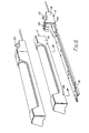
- the assembled lighting unit comprises: a cartridge 2 comprising a strip lighting element 4 and a lighting element holder 5; and a cartridge holder 6.
- the lighting element holder 5 and the cartridge holder 6 are moulded plastics articles.
- the lighting element holder. 5 may be considered as a channelled member cut away in its middle region to leave channelled end portions 8 and 10, joined by a pair of thin, parallel strips 11.
- Each end portion comprises opposed side walls 12 and 14 and an interconnecting web 16.
- the strips 11 join the parts of the side walls 12 and 14 remote from the respective webs.
- Each end portion 8 and 10 has a U-shaped, insulating spring clip (not shown) secured to the inner surface of the web.
- the clips grip the ends of the element 4 to retain it firmly within the lighting element holder 5, with the end terminals of the element in contact with leaf spring contacts (also not shown).
- Both the input terminals 20 and 22 to the cartridge 2 are at one end 10 of the lighting element holder 5 (see Fig. 4).
- One leaf spring contact is connected directly to the adjacent terminal 20 and the other is connected to the other terminal 22 via wiring trained along the inner surface of one of the strips 11.
- a cylindrical projection 24 is on the inner surface of each side wall 12 and 14 of each end 8 and 10, adjacent the free edge of the side wall (that is, remote from the web).
- the projections 24 form two pairs and the projections of each pair generally oppose each other across the channel of a respective end portion 8, 10.
- One projection is shown in Fig. 5.
- the cartridge holder 6 has a base strip 26 which is slightly narrower than the width of the channel of the cartridge.
- the base strip 26 comprises a central portion 27 with downturned edges 28 extending along its length.
- the central portion 27 carries a reflective strip.
- Each edge 28 is formed with two identical slots 30.
- the slots form two pairs transversely aligned across the base strip.
- Each slot is generally L-shaped, having a transverse opening 32 sufficiently wide to enable a projection 24 to pass through it, and a portion formed longitudinally along the edge 28 and leading to an abutment face or blind wall 34.
- the base strip 26 joins a housing 36 which contains electrical contacts with which the input terminals 20 and 22 of the plug member can connect.
- the electrical contacts are connected to a mains lead 38.
- the housing 36 has a shaver socket 40 and a cord pull switch 42.
- Slit-shaped socket openings are provided in the end 44 of the housing 36 which faces the base strip 26.
- Three spaced apart mutually parallel guide plates 46 extend from the end 44, one between the socket openings and the others on either side of the openings.
- two gaps are provided in alignment with the socket openings.
- plates could of course be used to provide the two gaps, two plates being located between the socket openings.
- the outer surface of the housing 36 is identical in profile to the outer surface of the end portion 10 of the cartridge except for a shoulder portion 48 adjacent the end 44.
- the outer surface of this shoulder portion 48 is identical in profile to the inner surface of the end portion 10.
- the cartridge holder 6 is horizontally secured in a desired position, most commonly to a wall.
- the base strip 26 has screw holes 49 and spacers (not shown) are located beneath the screw holes to prevent the central portion 27 of the base strip being deformed towards the wall.
- the former is introduced onto the latter by moving it in a direction generally perpendicular to its axis.
- the projections 24 are aligned with and pass through the openings 32 of the slots 30 and the terminals 20 and 22 each pass within the appropriate gap between the guide plates 46.
- the side walls 12 and 14 of the ends 8 and 10 and the strips 11 of the cartridge fit snugly over the edges 28 of the base strip 26.
- the cartridge is then slid towards the housing 36.
- the projections slide within the slots 30 and the inner surface of the end portion 10 slides over the shoulder portion 48.
- the terminals 20 and 22 are guided into the socket openings and into electrical contact with the contacts within the housing.
- the lighting unit is now ready for use. Even if the power is left on during this installing procedure there is no danger to the observer as all live terminals are completely shielded and cannot be touched.
- slots 30 are short in relation to the length of the unit so that the unit can be installed in places of restricted width.
- the cartridge When the unit is in its assembled condition the cartridge is secure on the cartridge holder and is restrained against movement transverse to its length.
- the weight of the cartridge is supported by the interengaging structure of the two parts and the terminals 20 and 22 bear none of the weight.
- the only direction in which it can be moved is away from the housing, and in so doing, the terminals of the cartridge are disconnected from the electrical supply.
- the cartridge To replace a spent element the cartridge is simply slid away from its installed position adjacent the housing until it reaches its fully retracted position at which it can slide no further, as a result of the abutment of the projections 24 with the ends 50 of the slots, which ends are remote from the housing. In this retracted position the cartridge 2 is electrically isolated from the cartridge holder. The cartridge is now free to move transversely to its length, by pulling it away from the cartridge holder and allowing the projections 24 to pass through the openings 32. The cartridge is now completely free of the cartridge holder and the element can be replaced.
- the second embodiment of lighting unit shown in Figs. 6 to 8 has an identical cartridge 2 to that of Fig. 1 but a modified cartridge holder 6.
- the second embodiment does not have a shaver socket, and a push button switch 52 is provided instead of a cord pull.
- the profile of the end of the housing 36 which is to adjoin the end portion 10 of the cartridge matches the profile of the cartridge but the other end of the housing is of cut-away profile.
- the end 44 of the housing again has socket openings 54 into which the terminals of the cartridge must pass but the socket openings 54 are wider than those of the first embodiment and no guide plates are used.
- a further difference is in the region of the openings of the slots 30.
- the rear slots (one of which is shown in Fig. 7), are each approached by an inclined lead-in surface 56 to guide the projection 24 into opening 32 and thence into the longitudinal portion of the slot.
- the lead-in surfaces thus form ramps dropping towards the abutment face 34 and when the projections are moved down these ramps the cartridge is moved transversely (but not perpendicularly) to the axis of the lighting element.
- the front pair of slots one of which is shown in Fig.
Landscapes
- Engineering & Computer Science (AREA)
- General Engineering & Computer Science (AREA)
- Fastening Of Light Sources Or Lamp Holders (AREA)
- Vehicle Body Suspensions (AREA)
- Fluid-Damping Devices (AREA)
- Arrangement Of Elements, Cooling, Sealing, Or The Like Of Lighting Devices (AREA)
Claims (9)
Priority Applications (1)
| Application Number | Priority Date | Filing Date | Title |
|---|---|---|---|
| AT85301840T ATE35173T1 (de) | 1984-03-15 | 1985-03-15 | Leuchtarmatur. |
Applications Claiming Priority (2)
| Application Number | Priority Date | Filing Date | Title |
|---|---|---|---|
| GB08406823A GB2156062A (en) | 1984-03-15 | 1984-03-15 | Lighting unit |
| GB8406823 | 1984-03-15 |
Publications (2)
| Publication Number | Publication Date |
|---|---|
| EP0159145A1 EP0159145A1 (de) | 1985-10-23 |
| EP0159145B1 true EP0159145B1 (de) | 1988-06-15 |
Family
ID=10558157
Family Applications (1)
| Application Number | Title | Priority Date | Filing Date |
|---|---|---|---|
| EP85301840A Expired EP0159145B1 (de) | 1984-03-15 | 1985-03-15 | Leuchtarmatur |
Country Status (5)
| Country | Link |
|---|---|
| EP (1) | EP0159145B1 (de) |
| AT (1) | ATE35173T1 (de) |
| AU (1) | AU3985985A (de) |
| DE (1) | DE3563378D1 (de) |
| GB (1) | GB2156062A (de) |
Families Citing this family (11)
| Publication number | Priority date | Publication date | Assignee | Title |
|---|---|---|---|---|
| GB2194625B (en) * | 1986-08-21 | 1990-03-28 | Crabtree Electrical Ind Ltd | Improvements relating to lamp units |
| GB2221290B (en) * | 1988-07-29 | 1992-01-15 | Crossland Rolls Limited | Light fitting |
| DE9110312U1 (de) * | 1991-08-21 | 1992-03-26 | Zumtobel Licht Gmbh, Dornbirn | Lösbare Befestigung eines Reflektors an einem Leuchten-Geräteträger |
| GB9614777D0 (en) * | 1996-07-13 | 1996-09-04 | Menvier Electronic Eng Ltd | Lamp Assemblies |
| GB2344642A (en) * | 1998-11-27 | 2000-06-14 | Ibl Lighting Limited | Lamp assembly comprising a module which is attachable to a housing |
| DE29906741U1 (de) * | 1999-04-15 | 1999-07-08 | Spectral Gesellschaft für Lichttechnik mbH, 79111 Freiburg | Leuchte |
| DE19954068B4 (de) * | 1999-11-10 | 2010-11-25 | Zumtobel Lighting Gmbh | Leuchte |
| GB2364370B (en) * | 2000-07-03 | 2004-08-18 | Eterna Lighting Ltd | A light fitting for a double-ended tubular lamp |
| DE102006005295A1 (de) * | 2006-02-06 | 2007-08-09 | BSH Bosch und Siemens Hausgeräte GmbH | Beleuchtungsbaugruppe für ein Haushaltsgerät |
| DE102014215576B4 (de) * | 2014-08-06 | 2016-07-28 | Ridi Leuchten Gmbh | Leuchte |
| EP3736488B1 (de) * | 2019-05-07 | 2021-07-21 | BEGA Gantenbrink-Leuchten KG | Rechteckförmiges gehäuse |
Family Cites Families (6)
| Publication number | Priority date | Publication date | Assignee | Title |
|---|---|---|---|---|
| US1629568A (en) * | 1920-10-27 | 1927-05-24 | Benjamin Electric Mfg Co | Combination electrical connecter device and fixture support |
| DE827529C (de) * | 1949-11-27 | 1952-01-10 | Kandem App Und Leuchtenbau G M | Einrichtung von Leuchtroehrenleuchten zwecks leichter Auswechselung der Roehren |
| US2978575A (en) * | 1958-04-09 | 1961-04-04 | Globe Lighting Products Inc | Light fixture |
| US3772527A (en) * | 1972-11-24 | 1973-11-13 | Dual Lite Co | Self-contained emergency lighting units & adjustable swivel assemblies |
| US3840735A (en) * | 1973-08-06 | 1974-10-08 | Lightolier Inc | Vandal resistant and weatherproof lighting fixture |
| GB1526447A (en) * | 1975-12-30 | 1978-09-27 | F & T Building Prod Pty Ltd | Light fittings |
-
1984
- 1984-03-15 GB GB08406823A patent/GB2156062A/en not_active Withdrawn
-
1985
- 1985-03-14 AU AU39859/85A patent/AU3985985A/en not_active Abandoned
- 1985-03-15 AT AT85301840T patent/ATE35173T1/de not_active IP Right Cessation
- 1985-03-15 EP EP85301840A patent/EP0159145B1/de not_active Expired
- 1985-03-15 DE DE8585301840T patent/DE3563378D1/de not_active Expired
Also Published As
| Publication number | Publication date |
|---|---|
| DE3563378D1 (en) | 1988-07-21 |
| ATE35173T1 (de) | 1988-07-15 |
| GB8406823D0 (en) | 1984-04-18 |
| AU3985985A (en) | 1985-09-19 |
| GB2156062A (en) | 1985-10-02 |
| EP0159145A1 (de) | 1985-10-23 |
Similar Documents
| Publication | Publication Date | Title |
|---|---|---|
| EP0159145B1 (de) | Leuchtarmatur | |
| US2042105A (en) | Movable electric receptacle | |
| EP0156076B1 (de) | Adapter mit gleitendem Stiftenträger | |
| EP0159078B1 (de) | Vorrichtung zur Stromentnahme an einer Spannungsschiene | |
| US5370543A (en) | Electrical connector | |
| US4061406A (en) | High current carrying connector | |
| US3546367A (en) | Track for distribution of electricity | |
| US11967784B2 (en) | Tamper resistance receptacle | |
| US3699500A (en) | Fuse holder assembly | |
| US5577923A (en) | 125V/250V safety electric socket devices | |
| JPH11329550A (ja) | 2つのプラグのコネクタ部材とその雄雌部材及びコネクタ装置 | |
| JPH01304674A (ja) | 電気分配システム用接続装置 | |
| US2436586A (en) | Socket plug for electrical outlets | |
| US6468111B1 (en) | Electrical plug | |
| US3339170A (en) | Pressure lock grounding outlet | |
| US2184359A (en) | Combined switch and plug receptacle | |
| US3002170A (en) | Electronic data processing machine control panel and electrical contact therefor | |
| US4568137A (en) | Electrical connector having at least one fuse cartridge | |
| GB2229588A (en) | Electrical connector | |
| US2636097A (en) | Safety fuse and adaptor plug for electrical appliances | |
| US3569917A (en) | Electrical connector assembly | |
| US4547030A (en) | Electrical distribution system | |
| US2570104A (en) | Lamp socket for elongated tubular discharge lamps | |
| US4013849A (en) | Power pack plug switch | |
| EP0125141B1 (de) | Elektrische Steckdosen |
Legal Events
| Date | Code | Title | Description |
|---|---|---|---|
| PUAI | Public reference made under article 153(3) epc to a published international application that has entered the european phase |
Free format text: ORIGINAL CODE: 0009012 |
|
| AK | Designated contracting states |
Designated state(s): AT BE CH DE FR GB IT LI LU NL SE |
|
| 17P | Request for examination filed |
Effective date: 19860219 |
|
| RAP1 | Party data changed (applicant data changed or rights of an application transferred) |
Owner name: ETERNA LIGHTING LTD. |
|
| 17Q | First examination report despatched |
Effective date: 19870604 |
|
| GRAA | (expected) grant |
Free format text: ORIGINAL CODE: 0009210 |
|
| AK | Designated contracting states |
Kind code of ref document: B1 Designated state(s): AT BE CH DE FR GB IT LI LU NL SE |
|
| PG25 | Lapsed in a contracting state [announced via postgrant information from national office to epo] |
Ref country code: NL Effective date: 19880615 Ref country code: LI Effective date: 19880615 Ref country code: IT Free format text: LAPSE BECAUSE OF FAILURE TO SUBMIT A TRANSLATION OF THE DESCRIPTION OR TO PAY THE FEE WITHIN THE PRESCRIBED TIME-LIMIT;WARNING: LAPSES OF ITALIAN PATENTS WITH EFFECTIVE DATE BEFORE 2007 MAY HAVE OCCURRED AT ANY TIME BEFORE 2007. THE CORRECT EFFECTIVE DATE MAY BE DIFFERENT FROM THE ONE RECORDED. Effective date: 19880615 Ref country code: FR Free format text: THE PATENT HAS BEEN ANNULLED BY A DECISION OF A NATIONAL AUTHORITY Effective date: 19880615 Ref country code: CH Effective date: 19880615 Ref country code: BE Effective date: 19880615 Ref country code: AT Effective date: 19880615 |
|
| REF | Corresponds to: |
Ref document number: 35173 Country of ref document: AT Date of ref document: 19880715 Kind code of ref document: T |
|
| PG25 | Lapsed in a contracting state [announced via postgrant information from national office to epo] |
Ref country code: SE Effective date: 19880630 |
|
| REF | Corresponds to: |
Ref document number: 3563378 Country of ref document: DE Date of ref document: 19880721 |
|
| REG | Reference to a national code |
Ref country code: CH Ref legal event code: PL |
|
| EN | Fr: translation not filed | ||
| NLV1 | Nl: lapsed or annulled due to failure to fulfill the requirements of art. 29p and 29m of the patents act | ||
| PG25 | Lapsed in a contracting state [announced via postgrant information from national office to epo] |
Ref country code: LU Free format text: LAPSE BECAUSE OF NON-PAYMENT OF DUE FEES Effective date: 19890331 |
|
| PLBE | No opposition filed within time limit |
Free format text: ORIGINAL CODE: 0009261 |
|
| STAA | Information on the status of an ep patent application or granted ep patent |
Free format text: STATUS: NO OPPOSITION FILED WITHIN TIME LIMIT |
|
| 26N | No opposition filed | ||
| PG25 | Lapsed in a contracting state [announced via postgrant information from national office to epo] |
Ref country code: DE Effective date: 19891201 |
|
| PGFP | Annual fee paid to national office [announced via postgrant information from national office to epo] |
Ref country code: GB Payment date: 19940314 Year of fee payment: 10 |
|
| PG25 | Lapsed in a contracting state [announced via postgrant information from national office to epo] |
Ref country code: GB Effective date: 19950315 |
|
| GBPC | Gb: european patent ceased through non-payment of renewal fee |
Effective date: 19950315 |