EP0159105A2 - System zum Regeln des Flüssigkeitsstandes - Google Patents
System zum Regeln des Flüssigkeitsstandes Download PDFInfo
- Publication number
- EP0159105A2 EP0159105A2 EP85300354A EP85300354A EP0159105A2 EP 0159105 A2 EP0159105 A2 EP 0159105A2 EP 85300354 A EP85300354 A EP 85300354A EP 85300354 A EP85300354 A EP 85300354A EP 0159105 A2 EP0159105 A2 EP 0159105A2
- Authority
- EP
- European Patent Office
- Prior art keywords
- fluid
- chamber
- turbocharger
- axle housing
- housing
- Prior art date
- Legal status (The legal status is an assumption and is not a legal conclusion. Google has not performed a legal analysis and makes no representation as to the accuracy of the status listed.)
- Ceased
Links
Images
Classifications
-
- F—MECHANICAL ENGINEERING; LIGHTING; HEATING; WEAPONS; BLASTING
- F16—ENGINEERING ELEMENTS AND UNITS; GENERAL MEASURES FOR PRODUCING AND MAINTAINING EFFECTIVE FUNCTIONING OF MACHINES OR INSTALLATIONS; THERMAL INSULATION IN GENERAL
- F16H—GEARING
- F16H57/00—General details of gearing
- F16H57/04—Features relating to lubrication or cooling or heating
- F16H57/0447—Control of lubricant levels, e.g. lubricant level control dependent on temperature
-
- F—MECHANICAL ENGINEERING; LIGHTING; HEATING; WEAPONS; BLASTING
- F16—ENGINEERING ELEMENTS AND UNITS; GENERAL MEASURES FOR PRODUCING AND MAINTAINING EFFECTIVE FUNCTIONING OF MACHINES OR INSTALLATIONS; THERMAL INSULATION IN GENERAL
- F16N—LUBRICATING
- F16N19/00—Lubricant containers for use in lubricators or lubrication systems
- F16N19/006—Maintaining oil level
-
- Y—GENERAL TAGGING OF NEW TECHNOLOGICAL DEVELOPMENTS; GENERAL TAGGING OF CROSS-SECTIONAL TECHNOLOGIES SPANNING OVER SEVERAL SECTIONS OF THE IPC; TECHNICAL SUBJECTS COVERED BY FORMER USPC CROSS-REFERENCE ART COLLECTIONS [XRACs] AND DIGESTS
- Y10—TECHNICAL SUBJECTS COVERED BY FORMER USPC
- Y10T—TECHNICAL SUBJECTS COVERED BY FORMER US CLASSIFICATION
- Y10T74/00—Machine element or mechanism
- Y10T74/19—Gearing
- Y10T74/19991—Lubrication
Definitions
- This invention relates to a fluid level control system which regulates the level of fluid in a first chamber, such as an axle housing, for returning excess fluid from the first chamber to a second chamber, such as a main transmission housing.
- a hydraulic actuator such as a -_ differential clutch located within the axle assembly.
- the differential When the clutch is engaged, the differential is locked up and both axles are driven as one and when the clutch is released, both axles can be driven independently.
- Such hydraulic actuators are liable to leak at various joints or seals during operation and this leaked oil can increase the oil level within the axle housing. This presents a problem in that as the oil level increases, the efficiency of the axle decreases, greater cavitation can occur, and a larger quantity of oil is heated which can result in overheating of the axle assembly.
- the object of the present invention is to provide a fluid level control system which solves the above-identified problems in an efficient and economical manner.
- the invention is defined in the appended claims.
- the preferred embodiment uses pressurized air from a turbocharger to regulate the level of fluid in an axle housing by returning excess fluid from the axle housing to a transmission housing.
- the system includes a fluid supply line and a fluid return line connected between the transmission housing and the axle housing for circulating oil therebetween.
- a pump is connected in the supply line for supplying pressurized fluid to a hydraulic actuator which is positioned within the axle housing. This hydraulic actuator tends to leak fluid which can raise the level within the axle housing.
- a standpipe is positioned within the axle housing and has one end connected to the return line and a second open end located at a predetermined static fluid level.
- the system also includes an air intake line which connects the turbocharger to the axle housing via an orifice for limiting the rate of flow of pressurized air which can be directed to the axle housing.
- the pressurized air is of a sufficient value to overcome any head difference between the fluid level at the second end of the standpipe and the outlet of the return line as well as for overcoming any restrictions in the return line.
- This fluid level control system ensures that as the oil level increases above a predetermined static fluid level within the axle assembly, that the fluid can be recirculated to the transmission housing to be cooled.
- the orifice ensures that the efficiency of the turbocharger is reduced to a negligible extent.
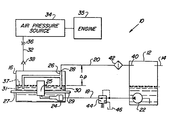
- the fluid level control system 10 can be utilized on off road equipment such as agricultural and industrial tractors or crawlers. Equally, the system 10 can easily be incorporated into stationary engines which incorporates drive mechanisms for rotating a drive shaft.
- the system 10 includes a transmission housing or case 12 which is vented to the atmosphere by a vent line 14.
- the transmission case 12 is connected to an axle housing 16 by a fluid supply line 18 and by a return line 20.
- a pump 22 feeds the supply line 18 for supplying pressurized fluid to a hydraulic actuator 24 located within the axle housing 16.
- the hydraulic actuator 24 can be a multiple disc clutch which is selectively engageable and disengageable to control a differential 25.
- the hydraulic actuator 24 tends to leak fluid especially during operation and this leaked fluid can raise the level within the axle housing 16.
- the static fluid level within the axle housing 16 should be set at approximately the horizontal centreline of the axle housing.
- the efficiency of the axle housing 16 decreases due to the fact that the gears in the differential 25 churn a greater quantity of oil as they rotate.
- the excess oil will result in increased cavitation and in the generation of a greater quantity of heat within the axle housing 16.
- a standpipe 26 is also positioned in the axle housing 16 and is connected at a first end 28 to the return line 20 and has a second open end 30 which is located at a predetermined static fluid level 31 in the axle housing 16.
- the fluid level control system 10 further includes an air intake line 32 which connects a source of pressurized air 34, for example a turbocharger, which is associated with an engine 35. Positioned in the air intake line 32 is an orifice 36 which limits the rate of flow of pressurized air which can be drawn from the turbocharger 34, without decreasing its efficiency by more than one percent. Preferably, the efficiency of the turbocharger 34 is not decreased by more than 0.5 percent, and most preferably by no more than 0.1 percent.
- the orifice 36 can be either a fixed or variable orifice.
- the size of the orifice 36 is adjusted to ensure that a rate of air flow at a sufficient pressure, is directed into the axle assembly 16.
- the pressurized air should be sufficient to cause any excess fluid above a predetermined working level 37 to be forced through the standpipe 26 and the return line 20 to the transmission case 12.
- the level 37 will be slightly higher than the static fluid level 31 due to cavitation and oil splashing.
- a non-return check valve 38 which is preferably a spring loaded check ball.
- the check valve 38 will open as pressurized air is routed from the turbocharger 34 into the axle housing 16 but will close should a situation arise wherein fluid and/or air pressure within the axle housing 16 rises and tries to flow upwards through the air intake line 32.
- the turbocharger 34 is operating at a low boost pressure and the oil is very cold, it is conceivable that the oil level will continue to rise above the predetermined working level 37 since the air pressure will be insufficient to cause it to recirculate back to the transmission case 12.
- the air pressure trapped therein will increase to the point where it would equalize the air pressure from the turbocharger 34 and therefore keep the check valve 38 closed.
- the pressure from the turbocharger 34 will increase, thereby opening the check valve 38 and causing the excess fluid within the axle housing 16 to be returned to the transmission case 12.
- the air pressure directed from the turbocharger 34 should be sufficient to overcome any head difference (AP) which is present between the predetermined working level 37 and an outlet opening 40 of the return line 20.
- the pressurized air in the axle housing 16 should-also be sufficient to overcome any restrictions which may exist in the return line 20, such as can be created by a filter 42.
- the fluid level control system 10 can also include a relief valve 44 in the supply line 18, to ensure that excess fluid can be returned to a reservoir 46 before any damage occurs to the hydraulic actuator 24.
Landscapes
- Engineering & Computer Science (AREA)
- General Engineering & Computer Science (AREA)
- Mechanical Engineering (AREA)
- Supercharger (AREA)
- Lubrication Details And Ventilation Of Internal Combustion Engines (AREA)
- Auxiliary Drives, Propulsion Controls, And Safety Devices (AREA)
- Arrangement Of Transmissions (AREA)
- Motor Power Transmission Devices (AREA)
- General Details Of Gearings (AREA)
- Retarders (AREA)
Applications Claiming Priority (2)
| Application Number | Priority Date | Filing Date | Title |
|---|---|---|---|
| US06/573,235 US4529061A (en) | 1984-01-23 | 1984-01-23 | Fluid level control system |
| US573235 | 1984-01-23 |
Publications (2)
| Publication Number | Publication Date |
|---|---|
| EP0159105A2 true EP0159105A2 (de) | 1985-10-23 |
| EP0159105A3 EP0159105A3 (de) | 1986-02-05 |
Family
ID=24291170
Family Applications (1)
| Application Number | Title | Priority Date | Filing Date |
|---|---|---|---|
| EP85300354A Ceased EP0159105A3 (de) | 1984-01-23 | 1985-01-21 | System zum Regeln des Flüssigkeitsstandes |
Country Status (10)
| Country | Link |
|---|---|
| US (1) | US4529061A (de) |
| EP (1) | EP0159105A3 (de) |
| JP (1) | JPS60169331A (de) |
| AR (1) | AR241324A1 (de) |
| AU (1) | AU566194B2 (de) |
| BR (1) | BR8500235A (de) |
| CA (1) | CA1221892A (de) |
| DK (1) | DK29085A (de) |
| ES (1) | ES8606682A1 (de) |
| ZA (1) | ZA85493B (de) |
Cited By (2)
| Publication number | Priority date | Publication date | Assignee | Title |
|---|---|---|---|---|
| EP0406649A1 (de) * | 1989-07-03 | 1991-01-09 | Deere & Company | Einrichtung zur Einstellung des Olstandes in einem Getriebe |
| EP1273829A3 (de) * | 2001-07-05 | 2005-06-29 | Deere & Company | Entlüftungseinrichtung für ein Getriebegehäuse |
Families Citing this family (14)
| Publication number | Priority date | Publication date | Assignee | Title |
|---|---|---|---|---|
| CH675758A5 (de) * | 1987-04-02 | 1990-10-31 | Walter Baiker Dipl Ing | |
| US5400889A (en) * | 1993-09-21 | 1995-03-28 | Agco Corporation | Clutch assembly with automatic oil level control system |
| DE19823524A1 (de) * | 1998-05-26 | 1999-12-02 | Linde Ag | Verbund(kälte)anlage und Verfahren zum Betreiben einer Verbund(kälte)anlage |
| US20040140162A1 (en) * | 2003-01-22 | 2004-07-22 | Celini Dean A. | Apparatus for setting fluid level in an automatic transmission |
| DE102008055632B4 (de) * | 2008-11-03 | 2012-05-16 | Aerodyn Engineering Gmbh | Verfahren zur Schmierung eines Getriebes |
| DE102009045426A1 (de) * | 2009-10-07 | 2011-04-14 | Zf Friedrichshafen Ag | Anordnung zum Ausgleich von Ölniveaus in Gehäuseteilen eines Getriebes |
| US20120180482A1 (en) * | 2011-01-19 | 2012-07-19 | Davorin Kapich | Hydraulic turbine-pump hybrid turbocharger system |
| DE102011012863A1 (de) * | 2011-03-03 | 2012-09-06 | Rolls-Royce Deutschland Ltd & Co Kg | Ölversorgungssystem für ein Flugtriebwerk |
| DE102011088363A1 (de) * | 2011-12-13 | 2013-06-13 | Zf Friedrichshafen Ag | Vorrichtung zum Einstellen eines Fluidfüllstandes in einem Gehäusebereich |
| US20160017981A1 (en) * | 2014-07-17 | 2016-01-21 | Baldor Electric Company | Gear Box Grease Seal System |
| US10124844B2 (en) * | 2015-04-28 | 2018-11-13 | Cnh Industrial America Llc | System and method for supplying fluid to a track drive box of a work vehicle |
| GB201611779D0 (en) * | 2016-07-06 | 2016-08-17 | Agco Int Gmbh | Utility vehicle lubrication and cooling |
| DE102020123621A1 (de) * | 2020-09-10 | 2022-03-10 | Deere & Company | Oelmanagementsystem |
| DE102020123650A1 (de) | 2020-09-10 | 2022-03-10 | Deere & Company | Getriebeschmiersystem |
Family Cites Families (9)
| Publication number | Priority date | Publication date | Assignee | Title |
|---|---|---|---|---|
| US2617495A (en) * | 1950-05-04 | 1952-11-11 | Westinghouse Electric Corp | Lubrication apparatus |
| US3241746A (en) * | 1965-02-08 | 1966-03-22 | Carrier Corp | Compressor lubricant equalizing pump |
| US3458011A (en) * | 1967-12-22 | 1969-07-29 | Gen Electric | Lubrication - supply system utilizing blow-by gases to maintain a generally constant oil level |
| US3913414A (en) * | 1972-09-29 | 1975-10-21 | Deere & Co | Differential structure for preventing leakage of differential lock actuating fluid to the differential housing |
| US3862672A (en) * | 1973-07-12 | 1975-01-28 | Eaton Corp | Quick-change drive unit |
| US4184858A (en) * | 1975-02-28 | 1980-01-22 | Walker Robert A | Engine emission control device |
| US4235307A (en) * | 1978-10-27 | 1980-11-25 | Deere & Company | Remote transmission lubrication system |
| CA1098843A (en) * | 1978-10-31 | 1981-04-07 | Versatile Manufacturing Company, A Division Of Versatile Cornat Corporation | Lubrication pump and filter for axle assemblies |
| DE3129119C1 (de) * | 1981-07-23 | 1982-11-11 | Bayerische Motoren Werke AG, 8000 München | Vorrichtung zum Ergänzen des Schmieröls einer Brennkraftmaschine |
-
1984
- 1984-01-23 US US06/573,235 patent/US4529061A/en not_active Expired - Fee Related
- 1984-11-20 CA CA000468259A patent/CA1221892A/en not_active Expired
- 1984-12-21 AU AU37050/84A patent/AU566194B2/en not_active Withdrawn - After Issue
-
1985
- 1985-01-18 AR AR85299295A patent/AR241324A1/es active
- 1985-01-18 BR BR8500235A patent/BR8500235A/pt unknown
- 1985-01-21 EP EP85300354A patent/EP0159105A3/de not_active Ceased
- 1985-01-22 ZA ZA85493A patent/ZA85493B/xx unknown
- 1985-01-22 DK DK29085A patent/DK29085A/da not_active Application Discontinuation
- 1985-01-22 ES ES539733A patent/ES8606682A1/es not_active Expired
- 1985-01-23 JP JP60010727A patent/JPS60169331A/ja active Pending
Cited By (2)
| Publication number | Priority date | Publication date | Assignee | Title |
|---|---|---|---|---|
| EP0406649A1 (de) * | 1989-07-03 | 1991-01-09 | Deere & Company | Einrichtung zur Einstellung des Olstandes in einem Getriebe |
| EP1273829A3 (de) * | 2001-07-05 | 2005-06-29 | Deere & Company | Entlüftungseinrichtung für ein Getriebegehäuse |
Also Published As
| Publication number | Publication date |
|---|---|
| EP0159105A3 (de) | 1986-02-05 |
| ES539733A0 (es) | 1986-04-16 |
| JPS60169331A (ja) | 1985-09-02 |
| CA1221892A (en) | 1987-05-19 |
| BR8500235A (pt) | 1985-08-27 |
| AU3705084A (en) | 1985-08-01 |
| ZA85493B (en) | 1986-09-24 |
| US4529061A (en) | 1985-07-16 |
| AU566194B2 (en) | 1987-10-08 |
| DK29085A (da) | 1985-07-24 |
| ES8606682A1 (es) | 1986-04-16 |
| AR241324A1 (es) | 1992-05-29 |
| DK29085D0 (da) | 1985-01-22 |
Similar Documents
| Publication | Publication Date | Title |
|---|---|---|
| EP0159105A2 (de) | System zum Regeln des Flüssigkeitsstandes | |
| CA2372296C (en) | Vehicle lubricant temperature control | |
| US4434934A (en) | System for heating the operators cabin of a machine powered by an internal combustion engine | |
| US7549848B2 (en) | Device for adjusting the pumping capacity of a lubricant pump for an internal combustion engine | |
| DE69010127T2 (de) | Ausgleichskolben und Dichtungsanordnung. | |
| US5551384A (en) | System for heating temperature control fluid using the engine exhaust manifold | |
| DE4420841A1 (de) | Heizvorrichtung für Kraftfahrzeuge | |
| US5992515A (en) | Transmission fluid cooler-bypass unit for a transmission fluid cooling system | |
| DE60120629T2 (de) | Wassergekühlter Lüfterantrieb | |
| JPH0483955A (ja) | 自動変速機の作動圧回路 | |
| EP0964983B1 (de) | Hydraulisch angetriebener kühlventilator für fahrzeuge | |
| DE19902408C2 (de) | Automatgetriebe für Fahrzeuge mit einem hydrodynamischen Wandler | |
| US5564317A (en) | One-piece pressure relief valve for transmission cooling system | |
| DE60123001T2 (de) | Wasserpumpe, getrieben durch eine Flüssigkeitsreibungskupplung | |
| EP0179210B1 (de) | Lüfterkupplung | |
| US2530241A (en) | Power transmission for refrigerated motor vehicles | |
| US4487364A (en) | Arrangement for heating the operator's cabin of a machine driven by an internal combustion engine | |
| US7611002B2 (en) | Apparatus for the operation of a hydrodynamic torque converter and a therewith corresponding converter bypassing clutch of a transmission apparatus | |
| DE102008034973A1 (de) | Kühlsystem, insbesondere eines Kraftfahrzeuges | |
| US11105419B2 (en) | Transmission torque converter | |
| US4096693A (en) | Torque converter fluid control system for power transmission system | |
| US12169017B2 (en) | Vehicle transmission with a power take-off, vehicle and working machine arrangement | |
| US20050060078A1 (en) | Automatic fluid draining from a hydraulic system component of an automatic transmission | |
| US20060016186A1 (en) | Hydrostatic transmission with bypass valve | |
| JPS6310290B2 (de) |
Legal Events
| Date | Code | Title | Description |
|---|---|---|---|
| PUAI | Public reference made under article 153(3) epc to a published international application that has entered the european phase |
Free format text: ORIGINAL CODE: 0009012 |
|
| AK | Designated contracting states |
Designated state(s): AT BE CH DE FR GB IT LI NL SE |
|
| PUAL | Search report despatched |
Free format text: ORIGINAL CODE: 0009013 |
|
| RHK1 | Main classification (correction) |
Ipc: F16H 57/04 |
|
| AK | Designated contracting states |
Designated state(s): AT BE CH DE FR GB IT LI NL SE |
|
| 17P | Request for examination filed |
Effective date: 19860312 |
|
| 17Q | First examination report despatched |
Effective date: 19870507 |
|
| STAA | Information on the status of an ep patent application or granted ep patent |
Free format text: STATUS: THE APPLICATION HAS BEEN REFUSED |
|
| 18R | Application refused |
Effective date: 19880331 |
|
| RIN1 | Information on inventor provided before grant (corrected) |
Inventor name: GLASRUD, PENDER ANTON Inventor name: SULLIVAN, THOMAS MILO |