EP0159177A2 - Appareil pour la séparation et l'alimentation en disques d'une machine à copier des disques - Google Patents
Appareil pour la séparation et l'alimentation en disques d'une machine à copier des disques Download PDFInfo
- Publication number
- EP0159177A2 EP0159177A2 EP85302504A EP85302504A EP0159177A2 EP 0159177 A2 EP0159177 A2 EP 0159177A2 EP 85302504 A EP85302504 A EP 85302504A EP 85302504 A EP85302504 A EP 85302504A EP 0159177 A2 EP0159177 A2 EP 0159177A2
- Authority
- EP
- European Patent Office
- Prior art keywords
- disc
- sliding
- plate
- uppermost
- feeding
- Prior art date
- Legal status (The legal status is an assumption and is not a legal conclusion. Google has not performed a legal analysis and makes no representation as to the accuracy of the status listed.)
- Granted
Links
- 238000004804 winding Methods 0.000 claims description 8
- 238000004891 communication Methods 0.000 claims description 2
- 238000000034 method Methods 0.000 claims description 2
- 238000012840 feeding operation Methods 0.000 description 2
- 230000003287 optical effect Effects 0.000 description 2
- 238000010276 construction Methods 0.000 description 1
- 238000005192 partition Methods 0.000 description 1
- 238000000926 separation method Methods 0.000 description 1
Images

Classifications
-
- G—PHYSICS
- G11—INFORMATION STORAGE
- G11B—INFORMATION STORAGE BASED ON RELATIVE MOVEMENT BETWEEN RECORD CARRIER AND TRANSDUCER
- G11B17/00—Guiding record carriers not specifically of filamentary or web form, or of supports therefor
- G11B17/08—Guiding record carriers not specifically of filamentary or web form, or of supports therefor from consecutive-access magazine of disc records
- G11B17/10—Guiding record carriers not specifically of filamentary or web form, or of supports therefor from consecutive-access magazine of disc records with horizontal transfer to the turntable from a stack arranged with a vertical axis
-
- G—PHYSICS
- G11—INFORMATION STORAGE
- G11B—INFORMATION STORAGE BASED ON RELATIVE MOVEMENT BETWEEN RECORD CARRIER AND TRANSDUCER
- G11B5/00—Recording by magnetisation or demagnetisation of a record carrier; Reproducing by magnetic means; Record carriers therefor
- G11B5/86—Re-recording, i.e. transcribing information from one magnetisable record carrier on to one or more similar or dissimilar record carriers
Definitions
- the present invention relates 'to an automatic magnetic disc separating and feeding apparatus for a magnetic disc copying machine, for example a copying machine which is adapted to be loaded with the magnetic disc, to read and record on the disc, or only to copy the disc according to a command from a computer connected thereto, and then to have the disc removed therefrom.
- a magnetic disc copying machine for example a copying machine which is adapted to be loaded with the magnetic disc, to read and record on the disc, or only to copy the disc according to a command from a computer connected thereto, and then to have the disc removed therefrom.
- An apparatus for feeding a magnetic disc (hereinafter referred to as a "disc") for a disc copying machine is conventionally adapted to push out the lowermost one of stacked discs in order towards the copying machine.
- this action causes the envelope containing the lowermost disc to rub against that of the disc above which frequently causes the envelope of the lowermost disc to be caught by the flap of the envelope of the upper disc, resulting in many problems occurring in the disc feeding operation.
- the machanism for pushing out the disc to the copying machine is generally arranged to carry out the operation by inserting a pawl into a E pindle hole provided in the disc or the outer edge of the envelope. This not only leads to the damage of the envelope but can render the disc unserviceable.
- an object of the present invention to provide an automatic disc separating and feeding apparatus for a disc copying machine which is capable of effectively preventing damage to the disc and/or to its envelope.
- a disc separating and feeding apparatus for a disc copying machine comprising a support member arranged to support a stack of discs, a feeding device arranged to feed a disc to an operation station, and transfer means arranged to transfer the disc from the stack to the feeding device, characterised in that the transfer means comprises a suction mechanism arranged to remove by suction the uppermost disc, and a drive mechanism to move the removed disc to the feeding device.
- a method for separating and feeding a disc for use in a disc copying machine which comprises removing a disc from a stack of discs, and transferring the disc to an operation station characterised in that the uppermost disc of the stack is removed by suction, and subsequently transfered to a feeding device which feeds the removed disc to the operation station.
- an automatic disc'separating and feeding apparatus for a disc copying machine accoridng to the present invention is constructed to suck upwardly the uppermost one of a stack of discs to separate the uppermost disc from the stack and to moving the disc without applying to the disc any force that might cause rubbing or friction between the discs or their envelopes, to transfer it to a transport device such as a belt conveyor or the like.
- the apparatus includes a lifting device arranged to lift the support member to maintain the uppermost disc at a predetermined position.
- the lifting device may include a winding device, a wire connected between the winding device and the support member, and a position sensor.
- the suction mechanism comprises a reduced pressure source, a fixed plate and a sliding plate, the two plates being in sliding contact and having co-operating through-holes which are in communication with the reduced pressure source and which face the uppermost disc, whereby relative movement of the two plates varies the size of air vents formed by the co-operation of the through-holes.
- the drive mechanism includes a pin which passes through a slot in the stationary plate, which has one end fixed to the sliding plate and the other end fixed to a reciprocating device.
- an automatic disc separating and feeding apparatus for a disc copying machine comprising a receiving chamber for receiving discs therein; a supporting plate arranged in the receiving chamber to support a plurality of stacked discs thereon; a lifting device for constantly keeping uppermost one of the stacked discs at a predetermined position; a disc sucking and sliding device provided on the receiving chamber, the disc sucking and sliding device comprising a stationary plate formed with a plurality of through-holes and a sliding plate formed with a plurality of through-holes and arranged to intimately contact with the lower surface of the stationary plate; the through-holes of the stationary plate and sliding plate forming together air vents varied in size depending upon the sliding of the sliding plate; a negative pressure chamber provided through the disc sucking and sliding device on the receiving chamber; a mechanism for reciprocating the sliding plate; and a transport device positioned opposite to the disc sucking and sliding device.
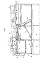
- reference numeral 1 designates a disc copying machine, which includes an automatic disc separating and feeding apparatus generally designated by reference numeral 2.
- the apparatus 2 includes a disc receiving chamber 3 for receiving discs 4 therein, a lifting device having a supporting plate 5, and a device 6 for carrying out the suction and sliding of each disc 4 which comprises a perforated stationary plate 7 and a perforated sliding plate 8.
- the sliding plate 8 has a pin 9 whose lower end is fixedly embedded therein so that it extends through the stationary plate 7 and has its upper end connected to a sliding drive mechanism 10.
- the apparatus 2 of the illustrated embodiment also includes a motor 11, a negative pressure chamber 12 and a blower 13 such as a sirocco fan or the like which serves to generate negative pressure in the chamber 12.
- the discs 4 stacked on the supporting plate 5 are positionally controlled to allow the uppermost disc 4b to be constantly at a predeterminded position.
- the lifting device comprises a lifting wire 14 connected to the supporting plate 5, a winding device 15 for winding up the lifting wire 14 and an optical sensor 16 for carrying out the on-off control of the winding device 15.
- Reference numeral 37 designates a limit switch for stopping the lowering of the supporting plate 5.
- the lifting device is adapted to keep the uppermost sidc 4b at a position directly beneath the sliding plate 8 and spaced from it by a distance of about 5-8mm.
- the uppermost disc 4b can be sucked onto the lower surface of the sucking and sliding plate 8 so that it takes up the position indicated by reference numeral 4a in FIGURE 1 when the negative pressure chamber 12 is under negative pressure.
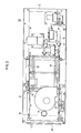
- FIGURES 3A and 3B The construction of the stationary plate 7 and sliding plate 8 of the disc sucking and sliding device 6 and the relationship in movement between both plates are shown in FIGURES 3A and 3B.
- the stationary plate 7 is arranged between side walls 18 and 19 of the apparatus 2 to serve as a partition plate and is provided with a plurality of through-holes 22 in two side portions between which a central hole 20 and a head hole 21 of a disc 4 would be located.
- the sliding plate 8 is supported below the stationary plate 7 in intimate contact with the plate 7 and is connected to the sliding drive mechanism 10.
- the sliding plate 8 is provided with a plurality of through-holes 23 at positions corresponding to the through-holes 22 of the stationary plate 7, through-holes 23 are larger than the through-holes 22 and elongated in the direction of movement of the sliding plate 8.
- the stationary plate 7 is at a suction position (the position shown in FIGURE 3A)
- the through-holes 22 and we are aligned with one another to form air vents 23a to allow a large suction force to be applied therethrough to the uppermost disc 4a, to suck the disc.
- the air vents 23a are constricted as indicated by 23b to weaken the suction force (as shown in FIGURE 3B).
- reference numeral 27 designates a door plate, and 28 and 29 each indicate an air suction port.
- the sliding plate 8 is adapted to be slided by a rectilinear reciprocating motion mechanism such as a cam, a groove crank or the like.
- the apparatus 2 further includes a sensor 25 for sensing the sucked disc 4a; and a slit 26 adjacent the sucked disc 4a, 2.5-3mm in height i.e. a size sufficient to allow only one disc to pass.
- the uppermost disc 4b located in a suction area of the apparatus is sucked up onto the lower surface of the sliding plate 8 so that it is separated upwards from the stacked discs 4.
- the uppermost disc can be smoothly separated without any harmful external force such as friction being applied thereto, and is ready for the subsequent feeding operation.
- the suction of the disc 4b onto the sliding plate 8 actuates the optical sensor 16 to drive the winding device 15, so that the uppermost disc of the stack may be kept at a predetermined position.
- any suitable discriminating device (not shown) confirms that there is no disc in the disc driving device (indicated 30) and that a transport and discharge device 31 is being driven, the sliding drive mechanism 10 is actuated to move the sliding plate 8 to the position shown in FIGURE 3B.
- the discriminating device is not included in the scope of the present invention and for the sake of brevity will not be discussed herein.
- the automatic disc separating and feeding apparatus of the illustrated embodiment is adapted to carry out the operation described above repeatedly.
- the apparatus of the present invention utilizes suction due to negative pressure to accomplish positively and safely the separation of a disc, thereby effectively preventing the disc and/or its envolope from being damaged. Also, the apparatus of the present invention performs the automatic loading of the disc to the driving device smoothly and without any harmful external force being applied to the disc, because the transfer of the disc to the transport device is carried out when the suction force is automatically substantially weakened.
Landscapes
- Sheets, Magazines, And Separation Thereof (AREA)
- Feeding And Guiding Record Carriers (AREA)
- Automatic Disk Changers (AREA)
Priority Applications (1)
| Application Number | Priority Date | Filing Date | Title |
|---|---|---|---|
| AT85302504T ATE69327T1 (de) | 1984-04-07 | 1985-04-09 | Plattentrennungs- und -speisungsgeraet fuer ein plattenkopiergeraet. |
Applications Claiming Priority (2)
| Application Number | Priority Date | Filing Date | Title |
|---|---|---|---|
| JP51287/84U | 1984-04-07 | ||
| JP1984051287U JPS60163551U (ja) | 1984-04-07 | 1984-04-07 | オ−トロ−ダにおける磁気デイスク自動分離供給装置 |
Publications (3)
| Publication Number | Publication Date |
|---|---|
| EP0159177A2 true EP0159177A2 (fr) | 1985-10-23 |
| EP0159177A3 EP0159177A3 (en) | 1988-12-07 |
| EP0159177B1 EP0159177B1 (fr) | 1991-11-06 |
Family
ID=12882712
Family Applications (1)
| Application Number | Title | Priority Date | Filing Date |
|---|---|---|---|
| EP85302504A Expired - Lifetime EP0159177B1 (fr) | 1984-04-07 | 1985-04-09 | Appareil pour la séparation et l'alimentation en disques d'une machine à copier des disques |
Country Status (5)
| Country | Link |
|---|---|
| US (1) | US4747005A (fr) |
| EP (1) | EP0159177B1 (fr) |
| JP (1) | JPS60163551U (fr) |
| AT (1) | ATE69327T1 (fr) |
| DE (1) | DE3584577D1 (fr) |
Families Citing this family (2)
| Publication number | Priority date | Publication date | Assignee | Title |
|---|---|---|---|---|
| US5019929A (en) * | 1988-09-01 | 1991-05-28 | Trace, Inc. | Magnetic media duplication system |
| WO2001077750A1 (fr) * | 2000-04-11 | 2001-10-18 | Drs Digitale Repro-Systeme Gmbh | Procede et dispositif destine a l'introduction automatique de documents a afficher sur une unite de visualisation et/ou a photographier dans un appareil de numerisation |
Family Cites Families (13)
| Publication number | Priority date | Publication date | Assignee | Title |
|---|---|---|---|---|
| US1906620A (en) * | 1928-07-12 | 1933-05-02 | Rca Corp | Talking machine |
| US2386166A (en) * | 1943-01-01 | 1945-10-02 | Internat Mutoscope Corp | Suction head |
| US2523257A (en) * | 1947-05-16 | 1950-09-19 | Supreme Enterprise Inc | Rotatable target for pin ball game apparatus |
| GB943359A (en) * | 1961-11-11 | 1963-12-04 | Deritend Eng Co | Improvements relating to suction feed mechanism for corrugated and like cardboard |
| US3341070A (en) * | 1964-12-17 | 1967-09-12 | Ibm | Record member guide device |
| GB1416727A (en) * | 1971-12-27 | 1975-12-03 | Ricoh Kk | Magnetic induction apparatus |
| US3782716A (en) * | 1972-06-29 | 1974-01-01 | Digi Data Corp | Device for selecting data cards |
| US4020504A (en) * | 1975-03-24 | 1977-04-26 | Minnesota Mining And Manufacturing Company | Automatic magnetic record sheet copying apparatus |
| JPS5276018A (en) * | 1975-12-22 | 1977-06-25 | Ricoh Co Ltd | Method of and device for preventing copying noise in magnetic copying apparatus |
| US4106062A (en) * | 1976-05-12 | 1978-08-08 | Addressograph Multigraph Corp. | Apparatus for producing magnetically encoded articles |
| US4206465A (en) * | 1977-02-08 | 1980-06-03 | Konishiroku Photo Industry Co., Ltd. | Photographically recording apparatus |
| EP0094240A3 (fr) * | 1982-05-11 | 1985-08-28 | Media Systems Technology Inc. | Dispositif de chargement automatique pour disques flexibles |
| CH651807A5 (fr) * | 1983-03-31 | 1985-10-15 | Bobst Sa | Dispositif d'asservissement des organes delivrant des feuilles prises dans une pile a une machine les travaillant. |
-
1984
- 1984-04-07 JP JP1984051287U patent/JPS60163551U/ja active Granted
-
1985
- 1985-04-05 US US06/720,269 patent/US4747005A/en not_active Expired - Fee Related
- 1985-04-09 EP EP85302504A patent/EP0159177B1/fr not_active Expired - Lifetime
- 1985-04-09 AT AT85302504T patent/ATE69327T1/de not_active IP Right Cessation
- 1985-04-09 DE DE8585302504T patent/DE3584577D1/de not_active Expired - Fee Related
Also Published As
| Publication number | Publication date |
|---|---|
| EP0159177B1 (fr) | 1991-11-06 |
| US4747005A (en) | 1988-05-24 |
| ATE69327T1 (de) | 1991-11-15 |
| JPS60163551U (ja) | 1985-10-30 |
| DE3584577D1 (de) | 1991-12-12 |
| EP0159177A3 (en) | 1988-12-07 |
| JPH026541Y2 (fr) | 1990-02-16 |
Similar Documents
| Publication | Publication Date | Title |
|---|---|---|
| EP1055621B1 (fr) | Système d'alimentation automatique de plaques | |
| EP0045436B1 (fr) | Dispositif à aspiration pour l'alimentation en documents | |
| US3971554A (en) | Sheet stacker | |
| JP2003015312A (ja) | 印刷版選別搬送装置 | |
| CN1325346C (zh) | 纸张类取出装置 | |
| US20030017035A1 (en) | Automatic printing plate feeding system | |
| CN1439143A (zh) | 卡片摞提升器和特殊输送 | |
| US4854569A (en) | Apparatus for taking out flexible work | |
| US7044056B2 (en) | Interleaf removal apparatus, plate feed apparatus and image recording system | |
| EP0159177B1 (fr) | Appareil pour la séparation et l'alimentation en disques d'une machine à copier des disques | |
| US4768769A (en) | Low cost rear air knife top vacuum corrugation feeder | |
| US5284334A (en) | Sheet feeding device | |
| US3917258A (en) | Sheet feeding equipment | |
| US6142462A (en) | Horizontal feed table and method | |
| US20030170099A1 (en) | Image recording material separating/removing device | |
| US20040216674A1 (en) | Wafer jar loader method, system and apparatus | |
| EP0110649B1 (fr) | Dispositif manipulateur de feuilles pour copieur | |
| JPS59186832A (ja) | 紙葉類移載機構 | |
| US4946157A (en) | Sheet loading and unloading mechanism | |
| US7168698B2 (en) | Sheet sucking/removing method and sheet sucking/removing device | |
| JP3841574B2 (ja) | 板ばね供給装置 | |
| JPH10120277A (ja) | 短冊状金属板の積載装置 | |
| JP2687318B2 (ja) | 密着板の分離装置 | |
| JPH09118446A (ja) | 上部供給形吸引式波形フィーダにおけるタブ付シートの取扱を容易にする装置 | |
| JPH08192930A (ja) | 板材の一枚取り方法およびその装置 |
Legal Events
| Date | Code | Title | Description |
|---|---|---|---|
| PUAI | Public reference made under article 153(3) epc to a published international application that has entered the european phase |
Free format text: ORIGINAL CODE: 0009012 |
|
| AK | Designated contracting states |
Designated state(s): AT BE CH DE FR GB IT LI LU NL SE |
|
| PUAL | Search report despatched |
Free format text: ORIGINAL CODE: 0009013 |
|
| AK | Designated contracting states |
Kind code of ref document: A3 Designated state(s): AT BE CH DE FR GB IT LI LU NL SE |
|
| 17P | Request for examination filed |
Effective date: 19890130 |
|
| 17Q | First examination report despatched |
Effective date: 19900516 |
|
| GRAA | (expected) grant |
Free format text: ORIGINAL CODE: 0009210 |
|
| AK | Designated contracting states |
Kind code of ref document: B1 Designated state(s): AT BE CH DE FR GB IT LI LU NL SE |
|
| REF | Corresponds to: |
Ref document number: 69327 Country of ref document: AT Date of ref document: 19911115 Kind code of ref document: T |
|
| ITF | It: translation for a ep patent filed | ||
| REF | Corresponds to: |
Ref document number: 3584577 Country of ref document: DE Date of ref document: 19911212 |
|
| ET | Fr: translation filed | ||
| PLBE | No opposition filed within time limit |
Free format text: ORIGINAL CODE: 0009261 |
|
| STAA | Information on the status of an ep patent application or granted ep patent |
Free format text: STATUS: NO OPPOSITION FILED WITHIN TIME LIMIT |
|
| 26N | No opposition filed | ||
| PGFP | Annual fee paid to national office [announced via postgrant information from national office to epo] |
Ref country code: GB Payment date: 19930326 Year of fee payment: 9 |
|
| PGFP | Annual fee paid to national office [announced via postgrant information from national office to epo] |
Ref country code: FR Payment date: 19930408 Year of fee payment: 9 |
|
| PGFP | Annual fee paid to national office [announced via postgrant information from national office to epo] |
Ref country code: AT Payment date: 19930415 Year of fee payment: 9 |
|
| PGFP | Annual fee paid to national office [announced via postgrant information from national office to epo] |
Ref country code: SE Payment date: 19930419 Year of fee payment: 9 |
|
| PGFP | Annual fee paid to national office [announced via postgrant information from national office to epo] |
Ref country code: CH Payment date: 19930420 Year of fee payment: 9 |
|
| PGFP | Annual fee paid to national office [announced via postgrant information from national office to epo] |
Ref country code: DE Payment date: 19930421 Year of fee payment: 9 |
|
| PGFP | Annual fee paid to national office [announced via postgrant information from national office to epo] |
Ref country code: NL Payment date: 19930430 Year of fee payment: 9 |
|
| PGFP | Annual fee paid to national office [announced via postgrant information from national office to epo] |
Ref country code: LU Payment date: 19930510 Year of fee payment: 9 |
|
| PGFP | Annual fee paid to national office [announced via postgrant information from national office to epo] |
Ref country code: BE Payment date: 19930513 Year of fee payment: 9 |
|
| EPTA | Lu: last paid annual fee | ||
| PG25 | Lapsed in a contracting state [announced via postgrant information from national office to epo] |
Ref country code: LU Free format text: LAPSE BECAUSE OF NON-PAYMENT OF DUE FEES Effective date: 19940409 Ref country code: GB Effective date: 19940409 Ref country code: AT Effective date: 19940409 |
|
| PG25 | Lapsed in a contracting state [announced via postgrant information from national office to epo] |
Ref country code: SE Effective date: 19940410 |
|
| PG25 | Lapsed in a contracting state [announced via postgrant information from national office to epo] |
Ref country code: LI Effective date: 19940430 Ref country code: CH Effective date: 19940430 Ref country code: BE Effective date: 19940430 |
|
| BERE | Be: lapsed |
Owner name: GRAPHICO K.K. Effective date: 19940430 |
|
| PG25 | Lapsed in a contracting state [announced via postgrant information from national office to epo] |
Ref country code: NL Effective date: 19941101 |
|
| GBPC | Gb: european patent ceased through non-payment of renewal fee |
Effective date: 19940409 |
|
| NLV4 | Nl: lapsed or anulled due to non-payment of the annual fee | ||
| PG25 | Lapsed in a contracting state [announced via postgrant information from national office to epo] |
Ref country code: FR Effective date: 19941229 |
|
| REG | Reference to a national code |
Ref country code: CH Ref legal event code: PL |
|
| PG25 | Lapsed in a contracting state [announced via postgrant information from national office to epo] |
Ref country code: DE Effective date: 19950103 |
|
| EUG | Se: european patent has lapsed |
Ref document number: 85302504.7 Effective date: 19941110 |
|
| REG | Reference to a national code |
Ref country code: FR Ref legal event code: ST |