EP1055621B1 - Système d'alimentation automatique de plaques - Google Patents
Système d'alimentation automatique de plaques Download PDFInfo
- Publication number
- EP1055621B1 EP1055621B1 EP00304201A EP00304201A EP1055621B1 EP 1055621 B1 EP1055621 B1 EP 1055621B1 EP 00304201 A EP00304201 A EP 00304201A EP 00304201 A EP00304201 A EP 00304201A EP 1055621 B1 EP1055621 B1 EP 1055621B1
- Authority
- EP
- European Patent Office
- Prior art keywords
- trays
- plates
- loading
- plate
- arm
- Prior art date
- Legal status (The legal status is an assumption and is not a legal conclusion. Google has not performed a legal analysis and makes no representation as to the accuracy of the status listed.)
- Expired - Lifetime
Links
- 238000011068 loading method Methods 0.000 claims description 41
- 238000003384 imaging method Methods 0.000 claims description 26
- 238000000926 separation method Methods 0.000 claims description 26
- 230000007246 mechanism Effects 0.000 claims description 21
- 238000000034 method Methods 0.000 claims description 7
- 230000003213 activating effect Effects 0.000 claims 2
- 238000007664 blowing Methods 0.000 description 1
- 230000001143 conditioned effect Effects 0.000 description 1
- 239000000463 material Substances 0.000 description 1
- 239000002184 metal Substances 0.000 description 1
Images




Classifications
-
- B—PERFORMING OPERATIONS; TRANSPORTING
- B65—CONVEYING; PACKING; STORING; HANDLING THIN OR FILAMENTARY MATERIAL
- B65H—HANDLING THIN OR FILAMENTARY MATERIAL, e.g. SHEETS, WEBS, CABLES
- B65H3/00—Separating articles from piles
- B65H3/08—Separating articles from piles using pneumatic force
- B65H3/0808—Suction grippers
- B65H3/0816—Suction grippers separating from the top of pile
- B65H3/0833—Suction grippers separating from the top of pile and acting on the front part of the articles relatively to the final separating direction
-
- B—PERFORMING OPERATIONS; TRANSPORTING
- B65—CONVEYING; PACKING; STORING; HANDLING THIN OR FILAMENTARY MATERIAL
- B65H—HANDLING THIN OR FILAMENTARY MATERIAL, e.g. SHEETS, WEBS, CABLES
- B65H3/00—Separating articles from piles
- B65H3/44—Simultaneously, alternately, or selectively separating articles from two or more piles
-
- B—PERFORMING OPERATIONS; TRANSPORTING
- B65—CONVEYING; PACKING; STORING; HANDLING THIN OR FILAMENTARY MATERIAL
- B65H—HANDLING THIN OR FILAMENTARY MATERIAL, e.g. SHEETS, WEBS, CABLES
- B65H2701/00—Handled material; Storage means
- B65H2701/10—Handled articles or webs
- B65H2701/17—Nature of material
- B65H2701/171—Physical features of handled article or web
- B65H2701/1719—Photosensitive, e.g. exposure, photographic or phosphor
-
- B—PERFORMING OPERATIONS; TRANSPORTING
- B65—CONVEYING; PACKING; STORING; HANDLING THIN OR FILAMENTARY MATERIAL
- B65H—HANDLING THIN OR FILAMENTARY MATERIAL, e.g. SHEETS, WEBS, CABLES
- B65H2701/00—Handled material; Storage means
- B65H2701/10—Handled articles or webs
- B65H2701/18—Form of handled article or web
- B65H2701/182—Piled package
- B65H2701/1826—Arrangement of sheets
- B65H2701/18264—Pile of alternate articles of different properties, e.g. pile of working sheets with intermediate sheet between each working sheet
Definitions
- the present invention generally relates to a system for loading a printing plate into a plate imaging device and specifically to a system for automatic loading of plates of various sizes into a plate setter or a printing plate imaging device.
- Plates are typically stacked in a cassette or similar container which houses the plates and facilitates their protection, transportation and handling.
- a specific system will using plates generally use trays having specific dimensions. Trays can usually be set to contain plates of various sizes, but all plates in the same tray are of one size. Usually the plates are manually removed from the cassette or the shipping container and inserted into the trays for use by the system, for example, a plate imaging system.
- Plates are usually packed in the cassette with intermediate paper sheets, hereinafter referred to as 'separation paper'.
- the separation papers are disposed during loading into the imaging device by a mechanism such as described in US-A-6164637 (published 26 December 2000) assigned to the common assignee of the present invention.
- FIG. 1 A typical conventional plate feeding system from a tray is shown schematically in Fig. 1. Plates 12 are supplied, within a tray 14, stacked one on top of the other with separation papers 16 between the plates.
- the feeding system includes a mechanism for disposing of the separation paper 16 into a paper bin 22 illustrated, for example.
- U.S Patent No. 5,367,360 to Mcllwraith et al. describes a method for loading plates from a single tray.
- the cardboard shipping container is used as a tray and the plates are lifted and loaded vertically by a vacuum system.
- US Patents 5,655,452, 5,738,014 5,791,250, 5,788,455 describe an apparatus and method of loading plates from a plurality of trays into an imaging device.
- the trays are stacked one on top of the other and moved by an elevator mechanism to allow a loading arm to enter between the trays and pick-up a specific plate.
- US-A-4483527 discloses a sheet-handling device including sheet boxes for processed and unprocessed boxes stacked vertically.
- a suction device having suction cups provided on a lower surface and being movable telescopically between the storage boxes and a worktable.
- the suction cups have nozzles for blowing air over the sheet material in transit.
- the present invention discloses a relatively compact system for automatically feeding plates of various sizes from a group of staggered trays.
- the present invention provides an automatic plate feeding system, which can be used to automatically feed plates of various sizes into a printing plate imaging device.
- the invention provides an apparatus for automatically loading printing plates into an imaging device, the apparatus comprising a plurality of trays for receiving printing plates of at least two different sizes and having separation paper interposed therebetween; an arm mechanism for loading plates from said plurality of trays and feeding said loaded plates to said imaging device; a loading plane positioned between the plurality of trays and the imaging device; and a control unit coupled to the arm mechanism and the imaging device, characterized in that the arm mechanism includes a motorized X-Y arm and is equipped with an array of suction cups mounted on a bar attached to a Y arm, and at least one sensor for distinguishing between plates and separation papers, and at least one paper removal gripper for gripping said separation papers, said sensor and said grippers being installed on the bar next to the suction cups, and said plurality of trays are staggered one on top of the other and each of the plurality of staggered trays and loading plane are equipped with at least one row of rollers, and the apparatus is operative to load plates from trays to loading plane by lifting and dragging plate over roller
- the arm mechanism includes a plate grasping member for grasping the plate and a separation paper disposing system.
- the grasping mechanism is movable perpendicularly to the arm by a vertical rod which is movable by the carriage.
- the carriage is movable along the arm which is typically parallel to the plates.
- the trays are staggered in a way that the grasping mechanism can be brought to each of the trays openings, grasp a plate and feed it to the imagesetter, or grasp a separation sheet and dispose it into the paper bin.
- the plate grasping member is an array of suction cups.
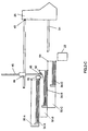
- Figs. 2A-2D illustrate the multi-tray plate loading system, generally designated 30, constructed and operative in accordance with an embodiment of the present invention.
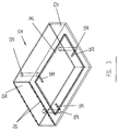
- Fig. 3 schematically illustrates a typical tray 32, for use with the multi-tray plate loading system of Fig. 2. Each tray 32 is shown containing a plurality of plates 34.
- the multi-tray plate loading system 30 is especially suitable for the automatic loading of plates of various sizes into a plate setter or a printing plate imaging device, schematically illustrated, referenced 25.
- the multi-tray plate loading system 30 includes a motorized arm mechanism, generally designated 36, pivotally connected to imaging device 25, for loading plates 34 from the trays 32 and feeding them to imaging device 25.
- a motorized arm mechanism generally designated 36, pivotally connected to imaging device 25, for loading plates 34 from the trays 32 and feeding them to imaging device 25.
- the multi-tray plate loading system 30 comprises a plurality of trays, referenced 32A, 32B and 32C holding stacks of plates referenced 34A, 34B and 34C respectively, of different sizes. Separation papers 38 are inserted to keep the plates apart from each other.
- the trays 32 are staggered one on top of the other.
- Arm mechanism 36 is pivotal about a pivot point 40. During the plate feeding/loading operation, arm mechanism 36 is substantially parallel to the stack of plates 34 in the trays 32. The arm mechanism 36 is tiltable so as to allow access to the trays 32.
- Arm mechanism 36 comprises an arm 42, a motorized carriage 44, which can be activated to move along the arm 42, and a vertical rod 46 connected to motorized carriage 44.
- the motorized carriage 44 can be stopped automatically at any desired position along arm 42.
- Vertical rod 46 is movable vertically (perpendicular to arm 42) through motorized carriage 44, and can be stopped automatically at any desired position.
- Vertical rod 46 comprises a bar 48 suitably attached to rod 46 at its lower end, and an array of suction cups 50 attached to bar 48.
- the bar 48 also carries separation grippers, (not shown) and sensors (not shown) which enable distinction between plate 34 and separation paper 38.
- the separation paper grippers may be any suitable known in the art devices, such as those described in US-A-6164637 (published 26 December 2000), assigned to the common assignee of the present invention, described hereinabove.
- the sensors may be any suitable known in the art devices and will not be further described.
- the distinguishing sensors are preferably of the electrical contact type, as known in the art.
- Motorized carriage 44 is coupled to a control unit 52, which is preferably coupled to the control unit of imaging device 25.
- Motorized carriage 44 is any suitable device, such as the commercially available model 2EC " Powerslide” of Thomson Ind. Industries, of New York, USA.
- loading plane 54 for receiving the plates being fed to imaging device 25.
- Fig. 3 illustrates a typical tray 32.
- the base of the tray 32 comprises three adjustable pins 58, located in slots 56, the adjustment of which defines the overall dimensions of the plate 34 being stored.
- Two pins are located proximal to an open end, referenced 60, and one of the pins is located approximately in the center and proximal to the other end, referenced 62.
- the pins 58 are inserted in the required slot 56, prior to loading the tray 32 with plates 34.
- the tray 32 is open at the top, thus allowing for easy loading of plates 34.
- the plates 34 are stacked with their imaging sensitive layer facing downwards.
- two rows of rollers 64 for guiding the plates 34 being fed, are suitably fitted.
- the dimensions of the tray 32 are determined by the maximum size of plates to be loaded and the maximum number of plates to be stacked.
- Fig. 4 is a flow chart illustration of a typical operation cycle of feeding a plate 34 to the imaging device 25.
- trays 32 are stacked one on top of the other, and offset a distance W, as shown.
- the motorized carriage 44 In the initial, non-activated mode, the motorized carriage 44 is located at its default position, that is at one end of arm 42, proximal to imaging device 25 (step 202). Vertical rod 46 is shown positioned at its highest point.
- step 204 Upon receiving a command from control unit 52 (Fig. 2B), to load a plate of a specific size (step 204), the motorized carriage 44 is activated to move along the arm 42 towards the tray containing the required plate (say plate 34B in tray 32B) - (step 206).
- step 208 Upon reaching the designated feeding position, motorized carriage 44 stops and vertical rod 46 descends until the suction cups 50 (together with separation paper grippers and distinguishing sensors (not shown)), are in contact with the uppermost plate in the tray (step 208).
- the following step is conditioned by the existence of separation paper between the plates, which might not exist for certain plates.
- the distinguishing sensors indicate to the computerized control unit 52, whether the top layer is a separation paper 38 or a plate 34 (query box 210). Accordingly, depending. on the upper layer, the computerized control unit 52 either activates the suction cups 50 (step 212) or the separation paper grippers (step 214).
- step 212 On sensing contact with a plate 34, arm 42 is tilted so that the suction cups 50 are perpendicular to the plate 34. The suction cups 50 are then operated to grasp the plate 34 (step 212).
- control unit 52 will activate the separation paper grippers (step 214) to grip the separation paper 38 and then dispose of it into the paper bin 22 (step 218).
- the plate loading sequence commences. As shown in Fig. 2C, vertical rod 46 is activated to move upwards a pre-determined amount, thus causing the suction cups 50 to lift the end of the plate 34 from the tray 32 (step 216).
- the motorized carriage 44 is then activated to move (step 220) towards the loading plane 54 of the imaging device 25, dragging the plate 34 out of tray 32.
- the rollers 64 facilitate the smooth movement of the plates 34 over the edge of the tray 32.
Landscapes
- Engineering & Computer Science (AREA)
- Mechanical Engineering (AREA)
- Sheets, Magazines, And Separation Thereof (AREA)
Claims (5)
- Appareil (30) pour le chargement automatique de plaques d'impression (34) dans un dispositif d'imagerie (25), l'appareil comprenant :caractérisé en ce que le mécanisme de bras (36) comprend un bras motorisé en X-Y (42, 44, 46) et est muni d'une rangée de coupelles d'aspiration (50) montées sur un bras (48) fixé à un bras en Y (46) ; etune pluralité de plateaux (32) pour recevoir des plaques d'impression (34) d'au moins deux dimensions différentes et possédant une feuille de papier de séparation (38) interposée entre elles ;un mécanisme de bras (36) pour charger les plaques (34) à partir de ladite pluralité de plateaux (32) et pour alimenter lesdites plaques chargées vers ledit dispositif d'imagerie (25) ;un plan de chargement (54) positionné entre la pluralité de plateaux (32) et le dispositif d'imagerie (25) ; etune unité de commande (52) couplée au mécanisme de bras (36) et au dispositif d'imagerie (25) ;
au moins un détecteur pour effectuer une discrimination entre les plaques (34) et les feuilles de papier de séparation (38), et au moins un moyen de prélèvement de feuille de papier pour saisir lesdites feuilles de papier de séparation (38), ledit détecteur et lesdits moyens de saisie étant placés sur la barre (48) à côté des coupelles d'aspiration (50) ; et
en ce que ladite pluralité de plateaux sont décalés l'un au-dessus de l'autre et chaque plateau de la pluralité de plateaux échelonnés (32) et le plan de chargement (54) sont équipés d'au moins une rangée de rouleaux (64) ; et
en ce que l'appareil est prévu pour charger des plaques (34) à partir des plateaux (32) vers le plan de chargement (54) en soulevant et en traínant la plaque (34) au-dessus des rouleaux (64) sur une distance de décalage (W) séparant les plateaux (32). - Appareil selon la revendication 1, dans lequel la distance de décalage (W) séparant les plateaux (32) est de 70 mm.
- Appareil selon la revendication 1, dans lequel les plateaux (32) sont équipés de broches réglables (58) permettant le chargement de plateaux (34) de diverses dimensions.
- Procédé pour le chargement de plaques (34) dans un appareil selon l'une quelconque des revendications précédentes, le procédé comprenant :a) le positionnement du bras motorisé en X-Y (36) au-dessus du plateau sélectionné (32) ;b) l'abaissement de la barre (48) pour entrer en contact avec la plaque supérieure (34) empilée dans le plateau sélectionné (32) ;c) l'activation du détecteur de papier pour déterminer la présence de la feuille de papier de séparation (38) ;d) l'enlèvement de la feuille de papier de séparation (38) à l'aide du moyen de saisie, au nombre minimum d'un ;e) l'activation des coupelles d'aspiration (50) et le soulèvement d'une seule plaque (34) en dehors du plateau (32) par l'intermédiaire du décalage W ;f) le traínage de la plaque soulevée (34) au-dessus des rouleaux (64) vers le plan de chargement (54) ;g) le relâchement de la plaque (34) et le retour du bras X-Y (36) vers sa position par défaut.
- Procédé selon la revendication 4, selon lequel les étapes a) à g) sont commandées par une unité de commande (52).
Applications Claiming Priority (2)
| Application Number | Priority Date | Filing Date | Title |
|---|---|---|---|
| IL13001899A IL130018A (en) | 1999-05-18 | 1999-05-18 | Automatic plate feeding system |
| IL13001899 | 1999-05-18 |
Publications (3)
| Publication Number | Publication Date |
|---|---|
| EP1055621A2 EP1055621A2 (fr) | 2000-11-29 |
| EP1055621A3 EP1055621A3 (fr) | 2001-10-31 |
| EP1055621B1 true EP1055621B1 (fr) | 2004-09-08 |
Family
ID=11072817
Family Applications (1)
| Application Number | Title | Priority Date | Filing Date |
|---|---|---|---|
| EP00304201A Expired - Lifetime EP1055621B1 (fr) | 1999-05-18 | 2000-05-18 | Système d'alimentation automatique de plaques |
Country Status (4)
| Country | Link |
|---|---|
| US (1) | US6422801B1 (fr) |
| EP (1) | EP1055621B1 (fr) |
| DE (1) | DE60013500T2 (fr) |
| IL (1) | IL130018A (fr) |
Families Citing this family (34)
| Publication number | Priority date | Publication date | Assignee | Title |
|---|---|---|---|---|
| JP3491557B2 (ja) * | 1999-04-22 | 2004-01-26 | 松下電器産業株式会社 | 電子部品供給用のトレイフィーダ |
| US20030017035A1 (en) * | 2000-05-15 | 2003-01-23 | Solomon Yehuda Barnes | Automatic printing plate feeding system |
| KR100311747B1 (ko) * | 1999-08-20 | 2001-10-18 | 정문술 | 표면실장기의 인쇄회로기판 이송장치 |
| JP2002316736A (ja) * | 2001-04-23 | 2002-10-31 | Fuji Photo Film Co Ltd | 印刷版枚葉搬送装置 |
| JP2002321840A (ja) * | 2001-04-25 | 2002-11-08 | Fuji Photo Film Co Ltd | 印刷版の枚葉装置 |
| JP2003015312A (ja) * | 2001-07-03 | 2003-01-17 | Fuji Photo Film Co Ltd | 印刷版選別搬送装置 |
| DE10134151B4 (de) * | 2001-07-13 | 2005-05-25 | Heidelberger Druckmaschinen Ag | Vorrichtung zum Vereinzeln von Druckplatten |
| JP3912665B2 (ja) * | 2002-03-06 | 2007-05-09 | 富士フイルム株式会社 | 画像記録材料枚葉装置 |
| JP4328075B2 (ja) * | 2002-04-22 | 2009-09-09 | 富士フイルム株式会社 | 感光性平版印刷版の製版システム及び製版方法 |
| JP2004018180A (ja) * | 2002-06-17 | 2004-01-22 | Dainippon Screen Mfg Co Ltd | 合紙取出装置 |
| US6776097B2 (en) * | 2002-10-02 | 2004-08-17 | Dainippon Screen Mfg. Co., Ltd. | Plate supplying apparatus |
| JP2004149313A (ja) | 2002-11-01 | 2004-05-27 | Fuji Photo Film Co Ltd | 搬送装置 |
| JP3897256B2 (ja) * | 2003-03-25 | 2007-03-22 | 富士フイルム株式会社 | 印刷版枚葉供給装置 |
| US7000543B2 (en) * | 2003-04-09 | 2006-02-21 | Esko-Graphics A/S | Method and apparatus for loading and unloading flexographic plates for computer-to-plate imaging |
| US6981447B2 (en) * | 2003-04-09 | 2006-01-03 | Esko-Graphics A/S | Method and apparatus for loading and unloading flexographic plates for computer-to-plate imaging |
| DE10330010B4 (de) * | 2003-07-03 | 2006-09-07 | Heidelberger Druckmaschinen Ag | Vorrichtung zum Anheben von einzelnen flächigen Objekten, insbesondere von zu belichtenden Druckplatten |
| DE102004020693A1 (de) * | 2004-04-28 | 2005-11-24 | Heidelberger Druckmaschinen Ag | Verfahren und Vorrichtung zur Bereitstellung und Übergabe von Kassetten für Druckplatten |
| US20060187287A1 (en) * | 2005-02-18 | 2006-08-24 | Lexmark International, Inc. | Method of printing with overlapping paper feed |
| US7861940B2 (en) | 2005-02-22 | 2011-01-04 | Eastman Kodak Company | Plate handling system |
| US7540372B2 (en) * | 2006-01-05 | 2009-06-02 | Ecrm, Inc. | Belt driven and roller assisted media transport |
| US7744078B2 (en) * | 2007-01-30 | 2010-06-29 | Eastman Kodak Company | Methods and apparatus for storing slip-sheets |
| US8167523B2 (en) * | 2007-07-12 | 2012-05-01 | Asm Assembly Automation Ltd | Singulation handler comprising vision system |
| US7806399B2 (en) * | 2007-12-12 | 2010-10-05 | Hewlett-Packard Development Company, L.P. | Media support pick device |
| CH710725B1 (de) * | 2008-04-17 | 2016-08-15 | Soudronic Ag | Hubtischabstapler sowie Behälterzargenschweissvorrichtung mit einem solchen. |
| US8235146B2 (en) * | 2009-12-11 | 2012-08-07 | Schlumberger Technology Corporation | Actuators, actuatable joints, and methods of directional drilling |
| US20110189600A1 (en) | 2010-01-29 | 2011-08-04 | Lars Plumer | Method for automated control of processing parameters |
| US20110188066A1 (en) | 2010-01-29 | 2011-08-04 | Lars Plumer | Processor system with provision for automated control of processing parameters |
| US8695960B2 (en) * | 2011-12-20 | 2014-04-15 | Xerox Corporation | Automatic media loading and unloading system for producing dimensional documents |
| US8826787B2 (en) * | 2012-08-22 | 2014-09-09 | Xerox Corporation | Cutting machine media feeder system with fixed in-feed and out-feed trays |
| CN104626765A (zh) * | 2013-11-13 | 2015-05-20 | 玉田元创包装机械制造有限公司 | 蓝图自动喷印机多路走纸系统 |
| US9227392B2 (en) * | 2014-05-21 | 2016-01-05 | Eastman Kodak Company | Slip sheet removal |
| KR101683490B1 (ko) * | 2014-08-12 | 2016-12-07 | 현대자동차 주식회사 | 연료전지 스택 제조 장치 및 방법 |
| JP6921673B2 (ja) * | 2017-07-25 | 2021-08-18 | Pacraft株式会社 | ピックアップ方法及びピックアップ装置 |
| WO2019155460A1 (fr) * | 2018-02-06 | 2019-08-15 | Assembrix Ltd. | Impression tridimensionnelle à étagères multiples |
Family Cites Families (17)
| Publication number | Priority date | Publication date | Assignee | Title |
|---|---|---|---|---|
| US4212263A (en) | 1978-11-15 | 1980-07-15 | Tasope' Limited | Printing plate processing machine |
| JPS58220030A (ja) | 1982-06-15 | 1983-12-21 | Dainippon Screen Mfg Co Ltd | シ−ト材の自動給排装置 |
| DE3440909A1 (de) | 1984-11-09 | 1986-05-15 | Dr.-Ing. Rudolf Hell Gmbh, 2300 Kiel | Vorrichtung zum vereinzeln von offset-druckplatten und entfernen von papierzwischenlagen |
| JPS62215444A (ja) * | 1986-03-14 | 1987-09-22 | Hitachi Ltd | Fic充▲てん▼用トレイの供給装置 |
| CA1311508C (fr) | 1987-01-07 | 1992-12-15 | Izumi Seto | Machine de debobinage automatique de pellicules photographiques |
| DE3705851A1 (de) * | 1987-02-24 | 1988-09-01 | Kodak Ag | Automatische filmeinlegevorrichtung fuer blattfilm-kassetten |
| JPH01154041A (ja) * | 1987-12-11 | 1989-06-16 | Toshiba Corp | 放射線診断装置 |
| DE4038544A1 (de) | 1990-12-04 | 1992-06-11 | Krause Biagosch Gmbh | Vorrichtung zur herstellung von druckplatten |
| IL106243A (en) | 1993-07-05 | 1996-01-31 | Scitex Corp Ltd | Inner beach type printer for printing plates |
| US5368284A (en) | 1993-08-30 | 1994-11-29 | I G Incorporated | Roll feed apparatus |
| US5367360A (en) | 1993-10-25 | 1994-11-22 | Creo Products Inc. | Automatic loader for unexposed printing plates |
| IL110467A (en) | 1994-07-26 | 1996-07-23 | Scitex Corp Ltd | System and method of conveying printing plates |
| US5788455A (en) | 1996-07-31 | 1998-08-04 | Agfa Divison, Bayer Corporation | Method and apparatus for picking and transporting plates in an automated platesetter |
| US5738014A (en) | 1996-07-31 | 1998-04-14 | Agfa Division, Bayer Corporation | Method and apparatus for making lithographic printing plates in an automated computer to plate imaging system |
| US5655452A (en) | 1996-08-07 | 1997-08-12 | Agfa Division, Bayer Corp. | Method and apparatus for an automated plate handler with slip sheet removal mechanism |
| US5809360A (en) | 1996-08-07 | 1998-09-15 | Agfa Division - Bayer Corporation | Cassette for storing and accessing plates within an automated plate handler |
| IL121699A (en) | 1997-09-03 | 2002-12-01 | Creoscitex Corp Ltd | Removes sheets with improved latch |
-
1999
- 1999-05-18 IL IL13001899A patent/IL130018A/xx not_active IP Right Cessation
-
2000
- 2000-05-15 US US09/571,325 patent/US6422801B1/en not_active Expired - Lifetime
- 2000-05-18 DE DE60013500T patent/DE60013500T2/de not_active Expired - Lifetime
- 2000-05-18 EP EP00304201A patent/EP1055621B1/fr not_active Expired - Lifetime
Also Published As
| Publication number | Publication date |
|---|---|
| US6422801B1 (en) | 2002-07-23 |
| EP1055621A3 (fr) | 2001-10-31 |
| IL130018A0 (en) | 2000-02-29 |
| DE60013500D1 (de) | 2004-10-14 |
| EP1055621A2 (fr) | 2000-11-29 |
| DE60013500T2 (de) | 2005-01-20 |
| IL130018A (en) | 2003-04-10 |
Similar Documents
| Publication | Publication Date | Title |
|---|---|---|
| EP1055621B1 (fr) | Système d'alimentation automatique de plaques | |
| US7229241B2 (en) | Automatic printing plate feeding system | |
| US8826787B2 (en) | Cutting machine media feeder system with fixed in-feed and out-feed trays | |
| JP2003015312A (ja) | 印刷版選別搬送装置 | |
| US5769413A (en) | Process and apparatus for automatic stack changing | |
| US5785309A (en) | Automatic plate feeding system and method | |
| CN113840789B (zh) | 具有机器人单元的基材处理系统及其运行方法 | |
| JPH06227692A (ja) | 積層板状物分離搬送装置 | |
| JP2662347B2 (ja) | シート積重ね装置 | |
| JPH05246606A (ja) | ソーターのシート搬送装置 | |
| US6524058B1 (en) | Assembly and method for stacking, conveying and lifting lids | |
| US7861940B2 (en) | Plate handling system | |
| EP1853501B1 (fr) | Systeme de manipulation de plaque | |
| US4946157A (en) | Sheet loading and unloading mechanism | |
| JP3325193B2 (ja) | ソータ | |
| JP2003012165A (ja) | 印刷版枚葉搬送装置用合紙排除機構 | |
| US12404123B2 (en) | Printing plate picking system and process | |
| US6817294B2 (en) | Plate storage and loading | |
| JP2521161Y2 (ja) | 給紙装置 | |
| EP0159177B1 (fr) | Appareil pour la séparation et l'alimentation en disques d'une machine à copier des disques | |
| US20040151571A1 (en) | Plate loader | |
| JP2003252460A (ja) | 画像記録装置 | |
| JPH06100184A (ja) | 画像形成装置のトレイ装置 | |
| WO2007136242A1 (fr) | Procédé et dispositif pour défaire une pile de feuilles souples | |
| JP2008094584A (ja) | シート集積装置及びこれを備えた画像形成装置 |
Legal Events
| Date | Code | Title | Description |
|---|---|---|---|
| PUAI | Public reference made under article 153(3) epc to a published international application that has entered the european phase |
Free format text: ORIGINAL CODE: 0009012 |
|
| AK | Designated contracting states |
Kind code of ref document: A2 Designated state(s): BE DE FR GB Kind code of ref document: A2 Designated state(s): AT BE CH CY DE DK ES FI FR GB GR IE IT LI LU MC NL PT SE |
|
| AX | Request for extension of the european patent |
Free format text: AL;LT;LV;MK;RO;SI |
|
| PUAL | Search report despatched |
Free format text: ORIGINAL CODE: 0009013 |
|
| AK | Designated contracting states |
Kind code of ref document: A3 Designated state(s): AT BE CH CY DE DK ES FI FR GB GR IE IT LI LU MC NL PT SE |
|
| AX | Request for extension of the european patent |
Free format text: AL;LT;LV;MK;RO;SI |
|
| 17P | Request for examination filed |
Effective date: 20020122 |
|
| RAP1 | Party data changed (applicant data changed or rights of an application transferred) |
Owner name: CREO IL. LTD. |
|
| AKX | Designation fees paid |
Free format text: AT BE CH CY LI |
|
| RBV | Designated contracting states (corrected) |
Designated state(s): BE DE FR GB |
|
| REG | Reference to a national code |
Ref country code: DE Ref legal event code: 8566 |
|
| 17Q | First examination report despatched |
Effective date: 20030220 |
|
| GRAP | Despatch of communication of intention to grant a patent |
Free format text: ORIGINAL CODE: EPIDOSNIGR1 |
|
| GRAS | Grant fee paid |
Free format text: ORIGINAL CODE: EPIDOSNIGR3 |
|
| GRAA | (expected) grant |
Free format text: ORIGINAL CODE: 0009210 |
|
| AK | Designated contracting states |
Kind code of ref document: B1 Designated state(s): BE DE FR GB |
|
| REG | Reference to a national code |
Ref country code: GB Ref legal event code: FG4D |
|
| REF | Corresponds to: |
Ref document number: 60013500 Country of ref document: DE Date of ref document: 20041014 Kind code of ref document: P |
|
| PLBE | No opposition filed within time limit |
Free format text: ORIGINAL CODE: 0009261 |
|
| STAA | Information on the status of an ep patent application or granted ep patent |
Free format text: STATUS: NO OPPOSITION FILED WITHIN TIME LIMIT |
|
| ET | Fr: translation filed | ||
| 26N | No opposition filed |
Effective date: 20050609 |
|
| REG | Reference to a national code |
Ref country code: FR Ref legal event code: CD |
|
| PGFP | Annual fee paid to national office [announced via postgrant information from national office to epo] |
Ref country code: FR Payment date: 20090507 Year of fee payment: 10 |
|
| PGFP | Annual fee paid to national office [announced via postgrant information from national office to epo] |
Ref country code: BE Payment date: 20090619 Year of fee payment: 10 |
|
| BERE | Be: lapsed |
Owner name: *KODAK IL LTD Effective date: 20100531 |
|
| REG | Reference to a national code |
Ref country code: FR Ref legal event code: ST Effective date: 20110131 |
|
| PG25 | Lapsed in a contracting state [announced via postgrant information from national office to epo] |
Ref country code: BE Free format text: LAPSE BECAUSE OF NON-PAYMENT OF DUE FEES Effective date: 20100531 |
|
| PG25 | Lapsed in a contracting state [announced via postgrant information from national office to epo] |
Ref country code: FR Free format text: LAPSE BECAUSE OF NON-PAYMENT OF DUE FEES Effective date: 20100531 |
|
| PGFP | Annual fee paid to national office [announced via postgrant information from national office to epo] |
Ref country code: GB Payment date: 20130425 Year of fee payment: 14 |
|
| PGFP | Annual fee paid to national office [announced via postgrant information from national office to epo] |
Ref country code: DE Payment date: 20140602 Year of fee payment: 15 |
|
| GBPC | Gb: european patent ceased through non-payment of renewal fee |
Effective date: 20140518 |
|
| PG25 | Lapsed in a contracting state [announced via postgrant information from national office to epo] |
Ref country code: GB Free format text: LAPSE BECAUSE OF NON-PAYMENT OF DUE FEES Effective date: 20140518 |
|
| REG | Reference to a national code |
Ref country code: DE Ref legal event code: R119 Ref document number: 60013500 Country of ref document: DE |
|
| PG25 | Lapsed in a contracting state [announced via postgrant information from national office to epo] |
Ref country code: DE Free format text: LAPSE BECAUSE OF NON-PAYMENT OF DUE FEES Effective date: 20151201 |