EP0159403A2 - Arrangement for correcting bundle errors in reduced-cyclic block codes - Google Patents
Arrangement for correcting bundle errors in reduced-cyclic block codes Download PDFInfo
- Publication number
- EP0159403A2 EP0159403A2 EP84115564A EP84115564A EP0159403A2 EP 0159403 A2 EP0159403 A2 EP 0159403A2 EP 84115564 A EP84115564 A EP 84115564A EP 84115564 A EP84115564 A EP 84115564A EP 0159403 A2 EP0159403 A2 EP 0159403A2
- Authority
- EP
- European Patent Office
- Prior art keywords
- syndrome register
- input
- output
- polynomial
- exclusive
- Prior art date
- Legal status (The legal status is an assumption and is not a legal conclusion. Google has not performed a legal analysis and makes no representation as to the accuracy of the status listed.)
- Ceased
Links
Images
Classifications
-
- H—ELECTRICITY
- H03—ELECTRONIC CIRCUITRY
- H03M—CODING; DECODING; CODE CONVERSION IN GENERAL
- H03M13/00—Coding, decoding or code conversion, for error detection or error correction; Coding theory basic assumptions; Coding bounds; Error probability evaluation methods; Channel models; Simulation or testing of codes
- H03M13/03—Error detection or forward error correction by redundancy in data representation, i.e. code words containing more digits than the source words
- H03M13/05—Error detection or forward error correction by redundancy in data representation, i.e. code words containing more digits than the source words using block codes, i.e. a predetermined number of check bits joined to a predetermined number of information bits
- H03M13/13—Linear codes
- H03M13/17—Burst error correction, e.g. error trapping, Fire codes
Definitions
- the invention relates to an arrangement for the correction of bundle errors with a maximum of b digits according to the "error trapping" method in cyclic block codes shortened by i digits with n digits, which consist of r digits for a test part and k digits for an information part assemble, with a r-stage syndrome register, in which a total input is connected via at least one exclusive OR gate connected between these stages, the position of which is derived from the coefficients of a pre-multiplication polynomial and in which the output of the last stage is connected via a first switch the input of the first stage and, via at least one further exclusive OR gate connected between these stages, is connected to further stages, the position of which is derived from the generator polynomial of the code, with a zero detection device having rb stages and connected to stages of the syndrome register, with an n steps and to the Total input connected buffer memory, with a last exclusive OR gate, one input of which is connected to the output of the buffer memory, the other input of which is
- error trapping method error trapping method
- a cyclic block code is defined by its generator polynomial g (x).
- a test part is arranged after the information part using a syndrome register with r levels. This creates a code word that can be represented mathematically as a polynomial with binary coefficients. This code word can be falsified during transmission. On the receiving side, it is designated v (x).
- Decoding at the receiving end is likewise carried out by means of a syndrome register with r stages. After entering the received code word, it contains only zeros if there are no errors. On the other hand, if there are errors, ones also occur.
- the bit pattern in the syndrome register after entering the code word is called a syndrome.
- the n-digit reception word v (x) which is to be regarded as a polynomial, is usually pre-multiplied automatically with the polynomial x r .
- this means that the receive word is output via an exclusive OR gate after the last stage of the syndrome register. After completing the entry, error correction begins. To the content of the syndrome register is cyclically shifted with closed feedback until the first rb stages contain only zeros. The last b levels then contain the error pattern.
- the block code is to be shortened by i bits, the first i bits of the information part of each code word are set to zero and are omitted after coding.
- the abbreviated code word must be filled in again with i zeros. The addition of zeros can be avoided if an additional pre-multiplication of the received code word is carried out with the polynomial x i , ie with a shortened block code the syndrome of the polynomial of the received code word v (x) multiplied by the polynomial x r + i is usually calculated .
- the pre-multiplication polynomial p 1 (x) must first be calculated, which results as the remainder of the division when the polynomial x r + i is divided by the generator polynomial g (x):
- the coefficients of p 1 (x) determine the positions at which the receive word must be entered into the syndrome register via exclusive OR gates.
- the object of the invention is to provide a correction arrangement for the shortened block code that requires fewer exclusive-OR gates.
- this object is achieved according to the invention in that the total input to the syndrome register via at least one exclusive OR gate connected between the stages of the syndrome register, the position of which is derived from the coefficients of a pre-multiplication polynomial P2 (x) is connected that the pre-multiplication polynomial p 2 (x) is the remainder of the division when the polynomial x b + i is divided by the generator polynomial g (x), that the zero-recognition device is connected to the last (rb) stages of the syndrome register and that the exit of the syndrome register is provided after its bth stage.
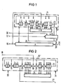
- FIG. 1 shows the basic circuit diagram of the correction arrangement according to the invention. This contains a syndrome register 15 with reset input 31, a zero detection device 24, a sequence control 25, a buffer memory 26, a switch 27, an exclusive OR gate 28, an input 16, an output 29, a synchronous signal input 17 and a clock input 30 .
- the input 16 is connected to the syndrome register 15 via the exclusive OR gate 18; the output of this syndrome register 15 leads to the switch 27.
- the switches 23 and 27 can be designed as a gate.
- FIGS. 1 and 2 Reference symbols not appearing in FIG. 1 are found in FIG. 2. The input signal is incorrect.
- the syndrome register 15 is opened Set to zero and the next code word is entered.
- An uncorrectable error is present if the error bundle is longer than b or if more than one error bundle occurs per code word.
- the synchronization signal at input 17 can be derived in any form from the code word at input 16.
- the feedbacks are from the output of stage 14, at the input of stage 1 and behind stages 2, 5, 9 and 11.
- the couplings cause exclusive-OR gates 19 to 22.
- the input 16 of the syndrome register 15 ' is therefore behind the stage 9.
- the coupling takes place via the Exclusive OR gate 18.
Landscapes
- Physics & Mathematics (AREA)
- Probability & Statistics with Applications (AREA)
- Engineering & Computer Science (AREA)
- Theoretical Computer Science (AREA)
- Error Detection And Correction (AREA)
Abstract
Die Korrekturanordnung empfängt am Eingang (16) ein Codewort. Dieses wird dem Syndromregister (15) vollständig zugeführt. Enthält das Syndromregister Fehler anzeigende Einsen, so wird sein Inhalt solange zyklisch verschoben, bis eine Nullen-Erkennungseinrichtung (24) an den höherwertigen Registerstufen eine Nullenfolge anzeigt. Die restlichen Registerstufen enthalten dann, sofern der Fehler korrigierbar ist, das Fehlermuster, das im Exklusiv-ODER-Gatter (28) mit dem aus dem Pufferspeicher (26) ausgelesenen Codewort an der Stelle des Bündelfehlers modulo-2- addiert wird, was zur Eliminierung des Fehlers führt.
Description
Die Erfindung bezieht sich auf eine Anordnung zur Korrektur von Bündelfehlern mit maximal b Stellen nach dem "Error-Trapping"-Verfahren in um i Stellen verkürzten zyklischen Blockcodes mit n Stellen, die sich aus r Stellen für einen Prüfteil und aus k Stellen für einen Informationsteil zusammensetzen, mit einem r Stufen aufweisenden Syndromregister, bei dem ein Gesamteingang über wenigstens ein zwischen diese Stufen geschaltetes Exklusiv-ODER-Gatter angeschlossen ist, dessen Lage aus den Koeffizienten eines Vormultiplikationspolynoms abgeleitet ist und bei dem der Ausgang der letzten Stufe über einen ersten Schalter mit dem Eingang der ersten Stufe und über wenigstens ein weiteres zwischen diese Stufen geschaltetes Exklusiv-ODER-Gatter mit weiteren Stufen verbunden ist, dessen Lage aus dem Generatorpolynom des Codes abgeleitet ist, mit einer r-b Stufen aufweisenden und an Stufen des Syndromregisters angeschlossenen Nullen-Erkennungseinrichtung, mit einem n Stufen aufweisenden und an den Gesamteingang angeschlossenen Pufferspeicher, mit einem letzten Exklusiv-ODER-Gatter, dessen einer Eingang mit dem Ausgang des Pufferspeichers, dessen anderer Eingang über einen zweiten Schalter mit dem Ausgang des Syndromregisters und dessen Ausgang mit einem Gesamtausgang verbunden ist, mit einer alle Schalter mit einem Synchronisierungssignal am Gesamteingang synchronisiert betätigenden Ablaufsteuerung und mit einer mit dem Bittakt des am Gesamteingang anliegenden Empfangssignals synchronisierten Taktversorgung.The invention relates to an arrangement for the correction of bundle errors with a maximum of b digits according to the "error trapping" method in cyclic block codes shortened by i digits with n digits, which consist of r digits for a test part and k digits for an information part assemble, with a r-stage syndrome register, in which a total input is connected via at least one exclusive OR gate connected between these stages, the position of which is derived from the coefficients of a pre-multiplication polynomial and in which the output of the last stage is connected via a first switch the input of the first stage and, via at least one further exclusive OR gate connected between these stages, is connected to further stages, the position of which is derived from the generator polynomial of the code, with a zero detection device having rb stages and connected to stages of the syndrome register, with an n steps and to the Total input connected buffer memory, with a last exclusive OR gate, one input of which is connected to the output of the buffer memory, the other input of which is connected to the output of the syndrome register via a second switch and the output of which is connected to an overall output, all of which have a synchronization signal at the total input synchronized sequence control and with one with the bit clock of the Synchronized clock supply present at the total input.
Eine derartige Anordnung ist aus dem Buch "Prüfbare und korrigierbare Codes" von W. Wesley Peterson, R. Oldenbourg-Verlag München und Wien, 1967, Seiten 256 bis 258, insbesondere Bild 10.4 bekannt.Such an arrangement is known from the book "Checkable and Correctable Codes" by W. Wesley Peterson, R. Oldenbourg-Verlag Munich and Vienna, 1967, pages 256 to 258, in particular Figure 10.4.
Bei zyklischen Blockcodes insbesondere zur Korrektur von Bündelfehlern der Länge b ist das sogenannte "Error-Trapping"-Verfahren (Fehler-fang-Verfahren) ein übliches Korrekturverfahren. Ein zyklischer Blockcode ist durch sein Generatorpolynom g(x) definiert.In the case of cyclic block codes, in particular for correcting bundle errors of length b, the so-called "error trapping" method (error trapping method) is a common correction method. A cyclic block code is defined by its generator polynomial g (x).
Sendeseitig wird mittels eines Syndromregisters mit r Stufen dem Informationsteil ein Prüfteil nachgeordnet. Es entsteht so ein Codewort, das sich mathematisch als Polynom mit binären Koeffizienten darstellen läßt. Dieses Codewort kann bei der Übertragung verfälscht werden. Empfangsseitig wird es mit v(x) bezeichnet.On the transmission side, a test part is arranged after the information part using a syndrome register with r levels. This creates a code word that can be represented mathematically as a polynomial with binary coefficients. This code word can be falsified during transmission. On the receiving side, it is designated v (x).
Eine empfangsseitige Decodierung erfolgt ebenfalls mittels eines Syndromregisters mit r Stufen. Nach Eingabe des empfangenen Codeworts enthält dieses bei Fehlerfreiheit ausschließlich Nullen. Sind dagegen Fehler vorhanden, dann treten auch Einsen auf. Das Bitmuster im Syndromregister nach Eingabe des Codeworts wird als Syndrom bezeichnet.Decoding at the receiving end is likewise carried out by means of a syndrome register with r stages. After entering the received code word, it contains only zeros if there are no errors. On the other hand, if there are errors, ones also occur. The bit pattern in the syndrome register after entering the code word is called a syndrome.
Um nach der Decodierung sofort mit der Fehlerkorrektur beginnen zu können, wird üblicherweise eine automatische Vormultiplikation des als Polynom aufzufassenden n-stelligen Empfangsworts v(x) mit dem Polynom xr vorgenommen. Das heißt schaltungstechnisch, daß das Empfangswort nach der letzten Stufe des Syndromregisters über ein Exklusiv-ODER-Gatter eirgegeben wird. Nach Abschluß der Eingabe beginnt die Fehlerkorrektur. Dazu wird der Inhalt des Syndromregisters bei geschlossener Rückkopplung solange zyklisch verschoben, bis die ersten r-b Stufen nur Nullen enthalten. Die letzten b Stufen enthalten dann das Fehlermuster.In order to be able to start error correction immediately after the decoding, the n-digit reception word v (x), which is to be regarded as a polynomial, is usually pre-multiplied automatically with the polynomial x r . In terms of circuitry, this means that the receive word is output via an exclusive OR gate after the last stage of the syndrome register. After completing the entry, error correction begins. To the content of the syndrome register is cyclically shifted with closed feedback until the first rb stages contain only zeros. The last b levels then contain the error pattern.
Soll der Blockcode um i Bits verkürzt werden, so werden die ersten i Bits des Informationsteils jedes Codeworts Null gesetzt und nach der Codierung weggelassen. Bei der Decodierung muß das gekürzte Codewort wieder mit i Nullen aufgefüllt werden. Das Anfügen von Nullen kann vermieden werden, wenn eine zusätzliche Vormultiplikation des empfangenen Codeworts mit dem Polynom xi vorgenommen wird, d.h. bei einem verkürzten Blockcode wird üblicherweise das Syndrom des mit dem Polynom xr+i multiplizierten Polynoms des empfangenen Codeworts v(x) berechnet. Zur Realisierung dieser Vormultiplikation muß zunächst das Vormultiplikations-Polynom p1(x) berechnet werden, das sich als Divisionsrest bei der Division des Polynoms xr+i durch das Generatorpolynom g(x) ergibt:
Die Koeffizienten von p1(x) bestimmen die Stellen, an denen das Empfangswort in das Syndromregister über Exklusiv-ODER-Gatter eingegeben werden muß.The coefficients of p 1 (x) determine the positions at which the receive word must be entered into the syndrome register via exclusive OR gates.
Bei der bekannten Korrekturanordnung für den verkürzten Blockcode sind selbst bei einer Verkürzung um nur wenige Bits gegenüber der Korrekturanordnung für den unverkürzten Code im allgemeinen mehrere zusätzliche Exklusiv-ODER-Gatter erforderlich.In the known correction arrangement for the shortened block code, even with a shortening by only a few bits compared to the correction arrangement for the unabridged code, a number of additional exclusive OR gates are generally required.
Aufgabe der Erfindung ist es, eine Korrekturanordnung für den verkürzten Blockcode anzugeben, die weniger Exklusiv-ODER-Gatter erfordert.The object of the invention is to provide a correction arrangement for the shortened block code that requires fewer exclusive-OR gates.
Ausgehend von einer Anordnung der einleitend geschilderten Art wird diese Aufgabe erfindungsgemäß dadurch gelöst, daß der Gesamteingang über wenigstens ein zwischen die Stufen des Syndromregisters geschaltetes Exklusiv-ODER-Gatter, dessen Lage aus den Koeffizienten eines Vormultiplikationspolynoms P2(x) abgeleitet ist, an das Syndromregister angeschlossen ist, daß sich das Vormultiplikationspolynom p2(x) als Divisionsrest bei der Division des Polynoms xb+i durch das Generatorpolynom g(x) ergibt, daß die Nullen-Erkennungseinrichtung an die letzten (r-b) Stufen des Syndromregisters angeschlossen ist und daß der Ausgang des Syndromregisters hinter seiner b-ten Stufe vorgesehen ist.Starting from an arrangement of the type described in the introduction, this object is achieved according to the invention in that the total input to the syndrome register via at least one exclusive OR gate connected between the stages of the syndrome register, the position of which is derived from the coefficients of a pre-multiplication polynomial P2 (x) is connected that the pre-multiplication polynomial p 2 (x) is the remainder of the division when the polynomial x b + i is divided by the generator polynomial g (x), that the zero-recognition device is connected to the last (rb) stages of the syndrome register and that the exit of the syndrome register is provided after its bth stage.
Die erfindungsgemäße Anordnung ist auch zur Korrektur von Einzelfehler korrigierenden zyklischen Blockcodes geeignet, wenn die Bündelfehlerlänge b=1 gesetzt wird.The arrangement according to the invention is also suitable for correcting cyclic block codes correcting individual errors if the bundle error length b = 1 is set.
Anhand von Ausführungsbeispielen wird die Erfindung nachstehend näher erläutert.
- Fig. 1 zeigt ein Prinzipschaltbild der erfindungsgemä-Ben Anordnung und
- Fig. 2 zeigt ein Syndromregister für einen um vier Bits verkürzten (279,265)-Fire-Code (n=279, k=265).
- 1 shows a basic circuit diagram of the arrangement and arrangement according to the invention
- FIG. 2 shows a syndrome register for a (279.265) fire code (n = 279, k = 265) shortened by four bits.
Figur 1 zeigt das Prinzipschaltbild der erfindungsgemäßen Korrekturanordnung. Diese enthält ein Syndromregister 15 mit Rücksetzeingang 31, eine Nullen-Erkennungseinrichtung 24, eine Ablaufsteuerung 25, einen Pufferspeicher 26, einen Schalter 27, ein Exklusiv-ODER-Gatter 28, einen Eingang 16, einen Ausgang 29, einen Synchronsignaleingang 17 und einen Takteingang 30.FIG. 1 shows the basic circuit diagram of the correction arrangement according to the invention. This contains a
Das Syndromregister 15 enthält ein Schieberegister mit r = n-k Stufen, das über einen Schalter 23 mit verschiedenen Stufeneingängen gekoppelt ist. Der Eingang 16 ist über das Exklusiv-ODER-Gatter 18 mit dem Syndromregister 15 verbunden; der Ausgang dieses Syndromregisters 15 führt zum Schalter 27.The
Die Schalter 23 und 27 können als Gatter ausgebildet sein.The
Für die Figuren 1 und 2 wurden dieselben Bezugszeichen gewählt. In Figur 1 nicht auftauchende Bezugszeichen finden sich in Figur 2. Das Eingangssignal sei fehlerhaft.The same reference symbols have been chosen for FIGS. 1 and 2. Reference symbols not appearing in FIG. 1 are found in FIG. 2. The input signal is incorrect.
Die Korrekturschaltung nach Figur 1 wirkt wie folgt:
- In den
Eingang 16 wird ein n-stelliges Codewort eingegeben und zwar sowohl in dasSyndromregister 15, das vor der Eingabe des Codeworts auf Null gesetzt wurde, als auch in denPufferspeicher 26. Der Inhalt desSyndromregisters 15 läuft über die Rückkopplungsschleife um, bis das gesamte Codewort eingegeben ist. Jetzt folgen über den Eingang 16 n Nullen nach. Im Syndromregister läuft der Inhalt jetzt solange um, bis die Nullen-Erkennungseinrichtung 24 in den Stufen (b+1) bis r ausschließlich Nullen erkennt. Jetzt wird über dieAblaufsteuerung 25 derSchalter 23 geöffnet und derSchalter 27 geschlossen. Vom Ausgang desSyndromregisters 15 nach der b-ten Stufe läuft jetzt der Inhalt der b Stufen, die das Fehlerbündel enthalten, über denSchalter 27 zum Exklusiv-ODER-Gatter 28, wo sie an der Fehlerstelle die aus demPufferspeicher 26 ausgelesenen Bits korrigieren.
- An n-digit code word is input into the
input 16, both in thesyndrome register 15, which was set to zero before the code word was entered, and in thebuffer memory 26. The content of the syndrome register 15 circulates through the feedback loop until the entire code word is entered. Now 16 zeros follow viainput 16. The content now circulates in the syndrome register until thezeros recognition device 24 in stages (b + 1) to r only recognizes zeros. Now theswitch 23 is opened via thesequence control 25 and theswitch 27 is closed. From the output of the syndrome register 15 after the bth stage, the content of the b stages containing the error bundle now runs via theswitch 27 to the exclusive-OR gate 28, where they correct the bits read out from thebuffer memory 26 at the error location.
Hat die Nullen-Erkennungseinrichtung 24 nach n Verschiebungen während der Korrekturphase nicht angesprochen, so lag ein nicht korrigierbarer Fehler vor. Nach der n-ten Verschiebung wird das Syndromregister 15 auf Null gesetzt und das nächste Codewort wird eingegeben.If the zero
Ein nicht korrigierbarer Fehler liegt vor, wenn das Fehlerbündel länger als b ist oder wenn mehr als ein Fehlerbündel pro Codewort auftritt.An uncorrectable error is present if the error bundle is longer than b or if more than one error bundle occurs per code word.
Wenn die Codewörter in unmittelbarer Folge übertragen werden, so sind, wenn der Schiebetakt der Register 15, 26 gleich dem Bittakt der empfangenen Codewörter ist, zwei Syndromregister erforderlich, die alternierend arbeiten.If the code words are transmitted in immediate succession, if the shift clock of the
Das Synchronisationssignal am Eingang 17 kann in irgend einer Form aus dem Codewort am Eingang 16 abgeleitet werden.The synchronization signal at input 17 can be derived in any form from the code word at
Figur 2 zeigt ein Syndromregister 15' für einen um i=4 Bits verkürzten (279,265)-Fire-Code mit dem Generatorpolynom
Entsprechend den Exponenten des Generatorpolynoms g(x) liegen die Rückkopplungen vom Ausgang der Stufe 14, am Eingang der Stufe 1 und hinter den Stufen 2, 5, 9 und 11. Die Einkopplungen bewirken Exklusiv-ODER-Gatter 19 bis 22.Corresponding to the exponents of the generator polynomial g (x), the feedbacks are from the output of stage 14, at the input of stage 1 and behind stages 2, 5, 9 and 11. The couplings cause exclusive-OR gates 19 to 22.
Für das Vormultiplikationspolynom zur Codeverkürzung gilt
Der Eingang 16 des Syndromregisters 15' liegt also hinter der Stufe 9. Die Einkopplung erfolgt über das Exklusiv-ODER-Gatter 18. Der Ausgang des Syndromregisters liegt wegen b = 5 hinter der Stufe 5.The
Claims (1)
dadurch gekennzeichnet , daß der Gesamteingang (16) über wenigstens ein zwischen die Stufen (1-14) des Syndromregisters (15, 15') geschaltetes Exklusiv-ODER-Gatter (18), dessen Lage aus den Koeffizienten eines Vormultiplikationspolynoms P2(x) abgeleitet ist, an das Syndromregister (15') angeschlossen ist,
characterized , that the total input (16) via at least one exclusive OR gate (18) connected between the stages (1-14) of the syndrome register (15, 15 '), the position of which is derived from the coefficients of a pre-multiplication polynomial P2 (x) the syndrome register (15 ') is connected,
Applications Claiming Priority (2)
| Application Number | Priority Date | Filing Date | Title |
|---|---|---|---|
| DE3415765 | 1984-04-27 | ||
| DE3415765 | 1984-04-27 |
Publications (2)
| Publication Number | Publication Date |
|---|---|
| EP0159403A2 true EP0159403A2 (en) | 1985-10-30 |
| EP0159403A3 EP0159403A3 (en) | 1987-11-11 |
Family
ID=6234539
Family Applications (1)
| Application Number | Title | Priority Date | Filing Date |
|---|---|---|---|
| EP84115564A Ceased EP0159403A3 (en) | 1984-04-27 | 1984-12-17 | Arrangement for correcting bundle errors in reduced-cyclic block codes |
Country Status (3)
| Country | Link |
|---|---|
| US (1) | US4698813A (en) |
| EP (1) | EP0159403A3 (en) |
| JP (1) | JPS617729A (en) |
Cited By (3)
| Publication number | Priority date | Publication date | Assignee | Title |
|---|---|---|---|---|
| AU583739B2 (en) * | 1986-07-21 | 1989-05-04 | Siemens Aktiengesellschaft | A method of and apparatus for data safeguarding |
| AU593870B2 (en) * | 1986-02-08 | 1990-02-22 | Sony Corporation | Apparatus for decoding a digital signal |
| WO1998026508A1 (en) * | 1996-12-12 | 1998-06-18 | Siemens Schweiz Ag | Method and circuit for decoding a cyclically coded signal |
Families Citing this family (9)
| Publication number | Priority date | Publication date | Assignee | Title |
|---|---|---|---|---|
| US4916702A (en) * | 1988-06-17 | 1990-04-10 | Cyclotomics, Inc. | Elongated burst trapping |
| US5381423A (en) * | 1989-07-25 | 1995-01-10 | Italtel Societa Italiana Telecomunicazioni S.P.A. | Process and device for the decoding of a shortened, cyclic binary code using error correction |
| US4978955A (en) * | 1989-11-09 | 1990-12-18 | Archive Corporation | Data randomizing/de-randomizing circuit for randomizing and de-randomizing data |
| US5107506A (en) * | 1990-01-25 | 1992-04-21 | Digital Equipment Corporation | Error trapping decoding method and apparatus |
| EP0611054B1 (en) * | 1993-01-22 | 1998-04-08 | Canon Kabushiki Kaisha | Polynomial-set deriving apparatus and method |
| US5473620A (en) * | 1993-09-21 | 1995-12-05 | Cirrus Logic, Inc. | Programmable redundancy/syndrome generator |
| US5936978A (en) * | 1996-12-05 | 1999-08-10 | Telefonaktiebolaget L M Ericsson (Publ) | Shortened fire code error-trapping decoding method and apparatus |
| US7155656B1 (en) * | 2003-05-01 | 2006-12-26 | Hellosoft Inc. | Method and system for decoding of binary shortened cyclic code |
| RU2251210C1 (en) * | 2003-10-06 | 2005-04-27 | Федеральное государственное унитарное предприятие "Калужский научно-исследовательский институт телемеханических устройств" | Noise-immune cyclic code codec |
Family Cites Families (7)
| Publication number | Priority date | Publication date | Assignee | Title |
|---|---|---|---|---|
| US3542756A (en) * | 1968-02-07 | 1970-11-24 | Codex Corp | Error correcting |
| US3801955A (en) * | 1971-12-13 | 1974-04-02 | Honeywell Inf Systems | Cyclic code encoder/decoder |
| US4059825A (en) * | 1976-10-12 | 1977-11-22 | Greene Edward P | Burst/slip correction decoder and method |
| EP0004718A1 (en) * | 1978-03-31 | 1979-10-17 | British Broadcasting Corporation | Method of and apparatus for decoding shortened cyclic block codes |
| JPS5546665A (en) * | 1978-09-30 | 1980-04-01 | Matsushita Electric Ind Co Ltd | Error corrector |
| DE3032468C2 (en) * | 1980-08-28 | 1986-01-23 | Siemens AG, 1000 Berlin und 8000 München | Circuit arrangement for recognizing the pattern of error bundles |
| US4488302A (en) * | 1983-02-11 | 1984-12-11 | At&T Bell Laboratories | Burst error correction using cyclic block codes |
-
1984
- 1984-12-17 EP EP84115564A patent/EP0159403A3/en not_active Ceased
-
1985
- 1985-04-26 JP JP60089149A patent/JPS617729A/en active Granted
- 1985-04-29 US US06/728,048 patent/US4698813A/en not_active Expired - Fee Related
Cited By (3)
| Publication number | Priority date | Publication date | Assignee | Title |
|---|---|---|---|---|
| AU593870B2 (en) * | 1986-02-08 | 1990-02-22 | Sony Corporation | Apparatus for decoding a digital signal |
| AU583739B2 (en) * | 1986-07-21 | 1989-05-04 | Siemens Aktiengesellschaft | A method of and apparatus for data safeguarding |
| WO1998026508A1 (en) * | 1996-12-12 | 1998-06-18 | Siemens Schweiz Ag | Method and circuit for decoding a cyclically coded signal |
Also Published As
| Publication number | Publication date |
|---|---|
| JPS617729A (en) | 1986-01-14 |
| JPH0221180B2 (en) | 1990-05-14 |
| US4698813A (en) | 1987-10-06 |
| EP0159403A3 (en) | 1987-11-11 |
Similar Documents
| Publication | Publication Date | Title |
|---|---|---|
| DE2060643C3 (en) | Circuit arrangement for correcting individual errors | |
| DE68924944T2 (en) | Error correction circuit. | |
| DE3787900T2 (en) | Method and device for generating test bytes for error detection for a data block. | |
| DE3855101T2 (en) | Arrangement for immediate error correction | |
| DE2916710C2 (en) | ||
| DE2657826A1 (en) | DEVICE FOR ERROR DETECTION AND ERROR CORRECTION IN THE STORAGE SYSTEM OF A IT SYSTEM | |
| DE2914515A1 (en) | METHOD AND DEVICE FOR AN EFFECTIVE ERROR DETECTION AND CORRECTION SYSTEM | |
| DE2942825A1 (en) | METHOD AND DEVICE FOR PROCESSING SEQUENTLY TRANSMITTING DIGITAL INFORMATION WORDS | |
| DE2425823A1 (en) | DEVICE FOR ERROR DETECTION AND ERROR CORRECTION | |
| DE3125048A1 (en) | GENERATION OF ERROR CORRECTION TEST BITS USING PARITY BITS FOR CONTINUOUS CONTROL | |
| DE2262070A1 (en) | ERROR CORRECTION SYSTEM WORKING WITH SLIDING REGISTERS | |
| DE2106314B2 (en) | Arrangement for error detection and correction in a byte consisting of b bits of a data block containing K data bytes | |
| DE2217935C3 (en) | Arrangement and method for correcting double errors in a message | |
| DE2153542A1 (en) | Encoder for a binary information bit sequence | |
| EP0545498A2 (en) | Method and circuit for decoding RS-coded data signals | |
| DE69317766T2 (en) | Error correction device for digital data for correcting single errors (sec), double errors (ded) and multiple single-byte errors (sbd) and for correcting single-byte errors of an odd number (odd sbc) | |
| DE1937249C3 (en) | Self-checking fault detection circuit | |
| DE3404417A1 (en) | CODER TEST CIRCUIT ARRANGEMENT | |
| DE4105860A1 (en) | Recognition and correction circuitry for faults in RS coded data blocks - has data word forward counter transmitting target value in determining zero position | |
| EP0003480B1 (en) | Circuit for converting binary information by means of check bits | |
| DE69429525T2 (en) | PROGRAMMABLE REDUNDANCY / SYNDROME GENERATOR | |
| DE69524430T2 (en) | CRC / EPC TEST SYSTEM | |
| DE2324538A1 (en) | DIGITAL MESSAGE TRANSFER ARRANGEMENT | |
| EP1047199B1 (en) | Data transmission device and method | |
| DE2047868A1 (en) | Circuit for correcting individual errors in the words of a cyclic (n, k) code |
Legal Events
| Date | Code | Title | Description |
|---|---|---|---|
| PUAI | Public reference made under article 153(3) epc to a published international application that has entered the european phase |
Free format text: ORIGINAL CODE: 0009012 |
|
| 17P | Request for examination filed |
Effective date: 19841228 |
|
| AK | Designated contracting states |
Designated state(s): AT BE CH DE FR GB IT LI NL SE |
|
| PUAL | Search report despatched |
Free format text: ORIGINAL CODE: 0009013 |
|
| AK | Designated contracting states |
Kind code of ref document: A3 Designated state(s): AT BE CH DE FR GB IT LI NL SE |
|
| 17Q | First examination report despatched |
Effective date: 19890706 |
|
| STAA | Information on the status of an ep patent application or granted ep patent |
Free format text: STATUS: THE APPLICATION HAS BEEN REFUSED |
|
| 18R | Application refused |
Effective date: 19900802 |
|
| RIN1 | Information on inventor provided before grant (corrected) |
Inventor name: ERDEL, KARLHEINZ, DIPL.-ING. |