EP0159438A2 - Multi-Dünnschicht-Wärmetransportmesser - Google Patents
Multi-Dünnschicht-Wärmetransportmesser Download PDFInfo
- Publication number
- EP0159438A2 EP0159438A2 EP84307352A EP84307352A EP0159438A2 EP 0159438 A2 EP0159438 A2 EP 0159438A2 EP 84307352 A EP84307352 A EP 84307352A EP 84307352 A EP84307352 A EP 84307352A EP 0159438 A2 EP0159438 A2 EP 0159438A2
- Authority
- EP
- European Patent Office
- Prior art keywords
- heat
- thin film
- heat flux
- heat transfer
- gauge
- Prior art date
- Legal status (The legal status is an assumption and is not a legal conclusion. Google has not performed a legal analysis and makes no representation as to the accuracy of the status listed.)
- Granted
Links
Images


Classifications
-
- G—PHYSICS
- G01—MEASURING; TESTING
- G01N—INVESTIGATING OR ANALYSING MATERIALS BY DETERMINING THEIR CHEMICAL OR PHYSICAL PROPERTIES
- G01N25/00—Investigating or analyzing materials by the use of thermal means
- G01N25/18—Investigating or analyzing materials by the use of thermal means by investigating thermal conductivity
Definitions
- This invention relates to a multi-layered thin film heat transfer gauge for determining heat flow into an object by measuring the temperature gradient across a thin, heat resistive film with resistance thermometers having metallic thin film elements. More particularly, the invention relates to a heat transfer gauge made of thin films overlaid one over the other and adapted to measure heat flux of long duration at high spatial resolution with quick response.
- a conventional heat transmission gauge of thin film type for instance that which has been used fairly frequently for measurement concerning shock wave tubes, has a heat-insulating substrate made of PYREX or the like and metallic thin films deposited on the substrate so as to form a resistance thermometer.
- the conventional heat transfer gauge of this type measures transient and non-steady surface temperature rise of an object caused by an input heat flux, and the heat flux at the surface of the object is determined from the thus measured temperature rise by calculation.
- This heat transfer gauge using thin films has been practically the only one which has a high spatial resolution and quick response.
- the conventional heat transfer gauge using thin films has a shortcoming in that, since its principle of measuring the heat flux is based on the transient temperature rise of the surface of a heat-insulating thermally non-conductive substrate, it is applicable only to the measurement of that heat flux which is produced in a wind tunnel with short flow duration. If such conventional heat transfer gauge is applied to the measurement of heat flux in a supersonic or low-speed wind tunnel with long flow duration, the surface temperature of an object is raised quickly and the conditions of constant-temperature wall are not satisfied, so that it cannot measure the steady state heat flux which is indispensable for heat flux measurement in such wind tunnels.
- the conventional heat transfer gauge of thin film type has been considered as the only one heat flux sensor having a high spatial resolution and a quick response, but it has a shortcoming in that it is applicable only to the measurement of heat flux in a shock wave tube or other wind tunnels with short flow duration, so that its scope of application is rather limited. In fact there is no such heat flux sensor with a high spatial resolution and a quick response which is applicable to the measurement of heat flux in a wind tunnel with long flow duration.
- an object of the present invention is to obviate the above-mentioned shortcomings of the prior art by providing an improved thin film heat transfer gauge having high spatial resolution and quick response, which gauge is capable of measuring steady state heat flux such as those in a wind tunnel with long flow duration.
- a thin film heat transfer gauge of the invention is applicable to the study of the phenomenon of local heat transfer in which heat flux varies greatly for a small shift of spatial position of measurement on a very fine scale. More particularly, the invention provides a multi-layered heat transfer gauge made of thin films overlaid one over another.
- Another object of the invention is to provide a thin film heat transfer gauge, more particularly a multi-layered heat transfer gauge made of thin films overlaid one over another, which gauge is suitable for measurement of heat flux in various technical fields where a high spatial resolution and a quick response are required.
- a further object of the invention is to provide a thin film heat transfer gauge, more particularly a multi-layered heat transfer gauge made of thin films overlaid one over another, which gauge is suitable for accurate measurement of thermal load encountered in aeronautical industry, space industry, machine industry, nuclear industry, or other industries involving heat transfer.
- the accurate measurement enabled by the heat transfer gauge of the invention will contribute to the imrpovement of the design of various machines and apparatus in those industries, such as machines and parts flying at a supersonic or hypersonic speed, turbine or other prime mover mechanism operating at a supersonic speed, and the like.
- an embodiment of the multi-layered heat transfer gauge of the invention uses a structure in which a pair of metallic thin films are bonded to opposite surfaces of a heat resistive thin film, the metallic thin films being connective with a resistance thermometer as elements thereof. Whereby, temperature gradient produced in the heat resistive thin film by a heat flux flowing therein is measured by the resistance thermometer connected with the metallic thin films, and the above heat flux is determined directly from the thus measured temperature gradient by calculation.
- Curves (a), (b), and (c) of Fig. 12 show waveforms of signals representing the sequence in which a measured value is calibrated;
- Curves (a) and (b) of Fig. 13 show, in a comparative manner, the result of calibration of measured values obtained by a gauge of the present invention and the result of measurement by a conventional thermocouple;
- Fig. 14 shows the measured characteristics curve of a multi-layered heat transfer gauge of the invention as compared with the corresponding characteristics curve of a conventional gauge
- Fig. 15 is a graph showing the result of a series of measurements obtained by using a multi-layered heat transfer gauge according to the invention.
- 1 is a substrate made of heat conductive material
- 2 is an electric insulation layer
- 3 is a heat resistive thin film
- 4 and 5 are metallic thin films acting as resistance thermometer elements
- 6 is a heat flux sensor
- 7 is a halogen lamp
- 8 is a shutter
- 9 is a probe
- 10 is an object being measured
- r 1 , r 2 are electric resistances of the metallic thin films
- L a , L b are lead wire portions
- a 1 and A 2 are D.C. amplifiers.
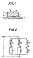
- Fig. 1 illustrates the basic structure of a multi-layered heat transfer gauge according to the present invention.
- a substrate 1 is made of a heat conductive material, and an electric insulation layer 2 which is thick enough for providing a required level of electric insulation is attached to top surface of the substrate 1.
- a heat resistive thin film 3 carries a pair of metallic thin films 4 and 5 bonded to the opposite surfaces thereof and this heat resistive thin film 3 is attached to the top surface of the electric insulation layer 2. Thereby, a heat flux sensor 6 is formed.
- the metallic thin films 4 and 5 act as elements of a resistance thermometer to be described hereinafter.
- the fundamental principles of the multi-layered heat transfer gauge of the invention with the above basic structure is as follows.
- the overall thickness of the heat flux sensor 6 having the heat resistive thin film 3 carrying the metallic thin films 4 and 5 is made very thin, and such thin heat flux sensor 6 is attached onto the surface of an object being measured while inserting the electric insulation layer 2 and the substrate 1 therebetween.
- the electric insulation layer 2 is so thin that it does not disturb the heat flow between the sensor 6 and the object being measured, and the substrate 1 is made of a heat conductive material.
- the heat flux of such heat flow produces a temperature gradient in the heat resistive thin film 3.
- Such temperature gradient can be measured by the metallic thin films 4 and 5 acting as resistive thermometer elements, and the heat flux through the heat resistive thin film 3 can be determined directly from the thus measured temperature gradient by calculation.
- the heat flux sensor 6 determines the heat flux through the heat resistive thin film 3 by measuring the temperature difference across the opposite surfaces of the heat resistive thin film 3 on the basis of the above-mentioned simple principle.
- the heat flux sensor 6 of the invention can determine the heat flux through an object or a field to be measured without disturbing the heat flow therein because the individual films constituting the multi-layered structure are very thin.
- the heat flux sensor 6 of the above structure according to the invention can be made very small, as will be described hereinafter by referring to examples, yet it has a high spatial resolution and a quick response, and its measured data can be easily calibrated as will be explained hereinafter.
- the multi-layered assembly in the heat flux sensor 6 of the invention comprises only the heat resistive thin film 3 carrying metallic thin films 4 and 5 bonded to the opposite surfaces thereof, and all such thin films 3, 4, and 5 can be easily produced and bonded by currently available thin film technology.
- the multi-layered assembly can be made by using various kinds of material in any shape with any desired dimensions so as to meet the need of specific application.
- AT is the temperature difference across the opposite surfaces of the heat resistive thin film 3, and such temperature difference can be indirectly determined by measuring the resistances r 1 and r 2 of the metallic thin films 4 and 5 between terminal lead portions L a and L b (see Fig. 3), which metallic thin films 4 and 5 are bonded to the opposite surfaces of the heat resistive thin film 3.
- the resistance r 1 and r 2 of the metallic thin films 4 and 5 are measured by a bridge circuit of Fig. 2. If the resistances of the metallic thin films 4 and 5 at temperature 0°C at which the bridge circuit is balanced are denoted by r 10 and r 20 , and the temperature coefficients of their resistances are denoted by a 1 and a 2 , then their resistances r 1 and r 2 corresponding to the temperature rise T 1 and T 2 are given by
- the temperature of the metallic films 4 and 5 and hence the average of the temperatures T 1 and T 2 at the opposite surfaces of the heat resistive thin film 3 vary over a fairly wide range even though the speed of such variation is slower than that of change in the temperature difference across the heat resistive thin film 3.
- the temperature coefficients a 1 and a 2 of the resistances of the metallic thin films 4 and 5 are different from each other in general.
- the correction as shown by the second term of the equation (5) is necessary. If the equations (3) and (4) are put to the equation (5) while neglecting their higher order terms, the heat flux qw can be finally given by the following equation (6) after rearrangement.
- the calibration coefficients y and ⁇ for the heat flux sensor 6 are calculated beforehand, and the bridge circuit outputs (e l -e 2 ) and (e 2 -e o ) are measured by using the heat flux sensor 6. Then, the heat flux qw is calculated from the thus measured bridge circuit outputs by using the equation (6).
- Fig. 7A and Fig. 7B show a plan view and an elevation of the heat flux sensor of Fig. 3, while Fig. 8A and Fig. 8B show a plan view and an elevation of the heat flux sensor of Fig. 6.
- the heat resistive thin film 3 was made of silicon monoxide, silicon dioxide or polyester, but such heat resistive thin film 3 can be made of ceramics or other suitable heat resistive material.
- the shape and the dimension of the heat resistive thin film 3 can be selected at will so as to meet the need of specific application.
- the material of the metallic thin films 4, 5 acting as resistance thermometer elements was nickel in the example mainly from the standpoint of economy, but it is also possible to make them with platinum so as to expand the temperature range for measurement.
- the shape and the dimension of the metallic thin films 4, 5 can be selected at will, too.
- the multi-layered heat transfer gauge can be made in a miniature size because of its simple structure comprising a heat resistive thin film 3 carrying metallic thin films 4, 5 deposited thereon so as to act as resistance thermometer elements. Accordingly, the multi-layered heat transfer gauge of the invention can measure the heat flux at a high spatial resolution with quick response, so that measurement by the gauge of the invention can accurately follow rapid changes in heat flux.
- the operating principle based on the steady state temperature gradient in the heat resistive thin film 3 renders a good steady state response to the gauge of the invention, which steady state response has not been available in the thin film type heat transfer gauge of the prior art.
- a multi-layered heat transfer gauge of the invention in the form of a heat flux sensor 6 is mounted on the top surface of a probe 9, which probe is formed as an integral part of an object 10 being measured by using the same material as that of the object 10.
- the probe 9 acts as the substrate 1 of the heat flux sensor 6.
- a number of highly sensitive heat flux sensors 6 are formed by depositing a number of paired metallic thin films 4 and 5 acting as resistance thermometer elements on opposite surfaces of a fairly large heat resistive thin film 3 at uniform intervals over the entire span of the film 3.
- the heat flux sensors 6 thus formed are attached to the top surface of the probe 9, so as to mount the sensors 6 on the object 10.
- a number of flexible heat flux sensors 6 are formed by depositing a number of paired metallic thin films 4 and 5 on opposite surfaces of a large flexible heat resistive thin film 3 at uniform intervals over the entire span of the film 3, and the thus formed sensors 6 are attached to a curved surface of the object 10 in tight contact therewith.
- the paired metallic thin films 4 and 5 are connected with a bridge circuit as shown in Fig. 10, so as to provide arm resistances of the bridge circuit.
- the bridge circuit of Fig. 10 measures the variation of the resistance values of the metallic thin films 4 and 5 as described above by referring to Fig. 2.
- the heat flux can be determined from the output of the bridge circuit in the form of the equations (3) and (4) through the calculation of the equation (6).
- the bridge circuit output levels (e l -e 2 ) and (e 2 -e o ) given by the equations (3) and (4) may be amplified by D.C. amplifiers A 1 and A 2 with gains G 1 and G 2 , and the thus amplified output levels G 1 (e 1 -e 2 ) and G 2 (e 2 -e o ) may be converted into digital signals so that heat flux is calculated by equation (6) with constants set therein, or may be input to an analogue circuit so that heat flux is obtained as an output.
- the calibration constants or coefficients to be used in the processing of the above output from the bridge circuit and the calculation in accordance with the equation (6) must be determined beforehand.
- the two constants y and 6 of the equation (7) can be determined separately. More particularly, the coefficient 6 can be determined as follows; namely, when a constant heat flux is applied to the heat transfer gauge of the invention, even if the differential voltage ratios ⁇ 12 and ⁇ 20 of the equation (6) vary in a non-steady manner, the finally obtained quantity ( ⁇ 12 + ⁇ 20 ) must be constant, and this condition facilitates the determination of 6.
- the coefficient y can be determined as follows; namely, after the above differential voltage ratios E12 and ⁇ 20 are stabilized at constant levels, the quantity ( ⁇ 12 + ⁇ 20 ) is calculated by using the coefficient ⁇ as determined above, and the coefficient y can be determined from the thus calculated quantity by using the equation (6).
- a halogen lamp 7 is held in a vertically slidable manner. After the halogen lamp 7 is fully heated, a shutter 8 is opened for irradiating a heat flux sensor 6 mounted on an object 10, so that heat flux is applied to the heat flux sensor 6 and non-steady output levels g 12 and ⁇ 20 are produced from which the coefficient 6 is determined in the manner described above. Cooling water CW is forced through the inside of the object 10, so that the surface temperature of the sensor is not raised too much by the halogen lamp 7.
- the curves (a), (b), and (c) of Fig. 12 show the non-steady output levels g 12 and ⁇ 20 obtained in the above manner and the output level obtained after calibration effected by the coefficient 6 derived in the above fashion.
- the curves of Fig. 12 indicate that the sensor output level ( ⁇ 12 + ⁇ 20 ) becomes constant after the above calibration.
- the frequency response characteristics and the sensitivity of the heat flux sensor according to the invention will be discussed now.
- the frequency response of the heat flux sensor 6 is approximately as shown in Fig. 4.
- the non-dimensional angular frequency w is determined from heat input sinusoidal frequency f, the thickness L of the heat resistive thin film 3, and the heat conductivity a of the heat resistive thin film 3 by the following formula.
- the cutoff frequency f at which the output level is reduced to 1/4Tof the value in the flat portion of the frequency response characteristics, is related to the thickness L of the heat resistive thin film 3 as shown by the following equation (8).
- ⁇ T max is the upper limit of the sensor surface temperature rise
- L max is the upper limit of the thickness of the heat resistive thin film
- A is the area of the metallic thin film acting as resistance thermometer elements
- y is the resistivity of the metallic thin film.
- the output of the heat flux sensor 6 is given as the sum of a differential component E12 representing difference of resistances of the metallic thin films 4 and 5 on the opposite surfaces of the heat resistive thin film 3 and an in-phase component ⁇ 20 representing the effect of the temperature rise of the sensor 6 itself.
- a ratio E between the measured quantity (qw/y) and the in-phase component ⁇ 20 can be defined as follows.
- the measuring error of both the differential and in-phase components ⁇ 12 , ⁇ 20 causes a digit-drop error with respect to the measured quantity (qw/y).
- thermometer elements a high accuracy of measurement can be ensured by selecting similar temperature coefficients a 1 and a 2 of electric resistance for the two metallic thin films 4 and 5 deposited on the opposite surfaces of the heat resistive thin film 3 as resistance thermometer elements and/or by setting the temperature difference (T 1 -T 2 ) between the two metallic thin films 4 and 5 as large as possible.
- a practical application of the multi-layered heat transfer gauge of the invention will be described next for the case of the measurement of heat transfer at a turbulent flow boundary layer.
- a flat plate model with a measuring cross-sectional area of 150 mm x 150 mm was placed in a supersonic wind tunnel while providing a cooling means as shown in Fig. 11. Measurement was made under the following conditions.
- Wall temperature to total temperature ratio T w/ T o 0.77 Reynolds number based on the distance of the measuring point from the leading edge of the flat plate model : 2.06 x 10 7
- Fig. 14 shows the result of the measurement.
- the solid line in the figure shows the heat flux as determined by the measurement with the heat flux sensor of the invention
- the dotted line of the figure shows reference values of the heat flux as determined by thermocouples mounted on the top and bottom surfaces of the flat plate model at a sideway distance of 10 mm from the sensor of the invention for the purpose of checking.
- the heat flux sensor of the invention provides the same output as that of the thermocouples in the steady state, and yet the sensor of the invention clearly has much faster response under transient conditions as compared with that of the thermocouples at both the starting and the breakdown of the wind tunnel.
- the coefficient of heat-transfer was measured by the heat flux sensor of the invention over the entire range of a so-called shock wave-turbulent boundary layer interaction which was produced by applying an oblique shock wave with a wedge angle of 10.0° to a turbulence boundary layer on a flat plate model placed in a supersonic wind tunnel.
- the result of the measurement is shown in Fig. 15.
- the conditions of the measurement were as follows.
- the heat flux sensor of the invention facilitates clear-cut observation and accurate measurement of the phenomenon that, in the interaction range, the coefficient of heat-transfer varies greatly in steps of spatially small scale.
- the heat flux sensor of the invention used in the above measurements had a spatial resolution of 0.2 mm and a cutoff frequency of the frequency response characteristics of 600 Hz, which spatial resolution and cutoff frequency have been impossible to obtain with the above-mentioned conventional heat flux sensors used in wind tunnels with long flow duration. Further improvement can be expected in the above characteristics of the heat flux sensor of the invention.
- a multi-layered heat transfer gauge comprises a heat resistive thin film having a pair of metallic thin films bonded to opposite surfaces thereof in a multi-layered fashion, the metallic thin films acting as resistance thermometer elements, so that the gauge can measure heat flux with a high spatial resolution and can follow rapid change of heat flux with a quick response. Since the measuring principle of the multi-layered heat transfer gauge of the invention is based on steady state temperature gradient in the heat resistive thin film thereof, it has an excellent steady state response characteristics which greatly exceeds that of a conventional thin film heat transfer gauge.
- the multi-layered heat transfer gauge of the invention facilitates the measurement of heat flux at a high spatial resolution in a wind tunnel having long flow duration and the measurement of rapid transient change in that flux with a quick response.
- the multi-layered heat transfer gauge of the invention simplifies the calibration of gauges of this kind.
- Conventional thin film heat transfer gauges require complicated electric circuits for calibration, but the measurement of the multi-layered heat transfer gauge of the invention can be calibrated easily with a minimum number of circuits.
- the multi-layered heat transfer gauge of the invention is very easy to handle and extremely simple in structure, so that it can be easily mounted on any desired location of an object.
- the level of the heat flux being measured can be determined directly from the measured output of the gauge, which output is in the form of output voltage from a bridge circuit connected with the metallic thin films acting as resistance thermometer elements.
- the invention provides a much simpler means for determining the heat flux as compared with conventional gauges therefor.
Landscapes
- Physics & Mathematics (AREA)
- Health & Medical Sciences (AREA)
- Life Sciences & Earth Sciences (AREA)
- Chemical & Material Sciences (AREA)
- Analytical Chemistry (AREA)
- Biochemistry (AREA)
- General Health & Medical Sciences (AREA)
- General Physics & Mathematics (AREA)
- Immunology (AREA)
- Pathology (AREA)
- Investigating Or Analyzing Materials Using Thermal Means (AREA)
- Measuring Temperature Or Quantity Of Heat (AREA)
Applications Claiming Priority (2)
| Application Number | Priority Date | Filing Date | Title |
|---|---|---|---|
| JP59057426A JPS60201224A (ja) | 1984-03-27 | 1984-03-27 | 多層薄膜熱伝達ゲ−ジ |
| JP57426/84 | 1984-03-27 |
Publications (3)
| Publication Number | Publication Date |
|---|---|
| EP0159438A2 true EP0159438A2 (de) | 1985-10-30 |
| EP0159438A3 EP0159438A3 (en) | 1986-12-17 |
| EP0159438B1 EP0159438B1 (de) | 1990-03-21 |
Family
ID=13055324
Family Applications (1)
| Application Number | Title | Priority Date | Filing Date |
|---|---|---|---|
| EP84307352A Expired EP0159438B1 (de) | 1984-03-27 | 1984-10-25 | Multi-Dünnschicht-Wärmetransportmesser |
Country Status (4)
| Country | Link |
|---|---|
| US (1) | US4577976A (de) |
| EP (1) | EP0159438B1 (de) |
| JP (1) | JPS60201224A (de) |
| DE (1) | DE3481727D1 (de) |
Cited By (3)
| Publication number | Priority date | Publication date | Assignee | Title |
|---|---|---|---|---|
| EP0419873A3 (en) * | 1989-08-30 | 1991-07-03 | Mitsui Toatsu Chemicals, Incorporated | Method and apparatus for measuring thermal diffusivity by ac joule-heating |
| WO2009078866A1 (en) * | 2007-12-18 | 2009-06-25 | Utc Power Corporation | Fuel cell systems and methods involving variable numbers of flow field passes |
| CN111947882A (zh) * | 2020-09-14 | 2020-11-17 | 中国空气动力研究与发展中心超高速空气动力研究所 | 一种瞬态热流传感器及其测试方法 |
Families Citing this family (44)
| Publication number | Priority date | Publication date | Assignee | Title |
|---|---|---|---|---|
| JPS60213834A (ja) * | 1984-04-09 | 1985-10-26 | Matsushita Electric Ind Co Ltd | 熱流センサ |
| JPS60230027A (ja) * | 1984-04-27 | 1985-11-15 | Matsushita Electric Ind Co Ltd | 熱流センサ |
| US4653934A (en) * | 1985-04-04 | 1987-03-31 | Lockheed Corporation | Heat flux meter |
| US4722609A (en) * | 1985-05-28 | 1988-02-02 | The United States Of America As Represented By The Secretary Of The Navy | High frequency response multilayer heat flux gauge configuration |
| US4812050A (en) * | 1985-05-28 | 1989-03-14 | The United States Of America As Represented By The Secretary Of The Navy | Method for calibrating a heat flux gauge |
| US4779994A (en) * | 1987-10-15 | 1988-10-25 | Virginia Polytechnic Institute And State University | Heat flux gage |
| US5216094A (en) * | 1987-12-23 | 1993-06-01 | Kansai Paint Company, Limited | Resins with unsaturated carbonyl and hydroxyl groups |
| GB8815609D0 (en) * | 1988-06-30 | 1988-08-03 | Atomic Energy Authority Uk | Temperature measurement of flowing fluids |
| US5026170A (en) * | 1989-06-07 | 1991-06-25 | The United States Of America As Represented By The United States Department Of Energy | Optical heat flux gauge |
| US5005984A (en) * | 1989-06-07 | 1991-04-09 | The United States Of America As Represented By The United States Department Of Energy | Optical heat flux gauge |
| US5044765A (en) * | 1989-06-07 | 1991-09-03 | United States Department Of Energy And United States Department Of Air Force | Optical heat flux gauge |
| JPH03123239U (de) * | 1990-03-29 | 1991-12-16 | ||
| US5273359A (en) * | 1992-04-03 | 1993-12-28 | The United States Of America As Represented By The United States Department Of Energy | Remote high-temperature insulatorless heat-flux gauge |
| US5314247A (en) * | 1993-04-16 | 1994-05-24 | The United States Of America As Represented By The Administrator Of The National Aeronautics & Space Administration | Dual active surface, miniature, plug-type heat flux gauge |
| US5356216A (en) * | 1993-05-03 | 1994-10-18 | Industrial Technology Research Institute | Apparatus for measuring heat of circuit module |
| US6040057A (en) | 1997-04-11 | 2000-03-21 | Karen M. Slimak | Enhancing the strength, moisture resistance, and fire-resistance of wood, timber, lumber, similar plant-derived construction and building materials, and other cellulosic materials |
| US6303234B1 (en) | 1996-03-15 | 2001-10-16 | K. M. Slimak | Process of using sodium silicate to create fire retardant products |
| US20020191671A1 (en) * | 2001-04-10 | 2002-12-19 | Ferrell Wayne M. | Method for thermal analysis of a clutch-brake system |
| EP1249691A1 (de) * | 2001-04-11 | 2002-10-16 | Omron Corporation | Elektronisches Fieberthermometer |
| US6821015B2 (en) * | 2002-01-25 | 2004-11-23 | Robert Hammer | Conducted heat vector sensor |
| JP4155749B2 (ja) * | 2002-03-20 | 2008-09-24 | 日本碍子株式会社 | ハニカム構造体の熱伝導率の測定方法 |
| US20040136434A1 (en) * | 2003-01-13 | 2004-07-15 | Langley Lawrence W. | Laminated heat flux indicating device |
| GB2401999B (en) * | 2003-05-20 | 2005-11-16 | Rolls Royce Plc | A lead |
| JP2005053250A (ja) * | 2003-08-01 | 2005-03-03 | Honda Motor Co Ltd | 自動車用エアバッグ装置 |
| TWM253059U (en) * | 2003-11-05 | 2004-12-11 | Arima Optoelectronics Corp | Full-color light emitting diode formed by overlapping three primary colors |
| US7077563B2 (en) * | 2003-11-19 | 2006-07-18 | General Electric Company | Deposition sensor based on differential heat flux measurement |
| EP1717566A1 (de) * | 2005-04-25 | 2006-11-02 | Mettler-Toledo AG | Thermoanalytischer Sensor |
| JP5230484B2 (ja) * | 2009-02-27 | 2013-07-10 | 三菱重工業株式会社 | 熱流束計測方法及び熱流束計測装置 |
| JP2012524261A (ja) * | 2009-04-15 | 2012-10-11 | アリザント ヘルスケア インク. | 深部組織用温度プローブ構造体 |
| EP2419004B1 (de) * | 2009-04-15 | 2017-07-19 | 3M Innovative Properties Company | Sondenkonstruktionen für tiefengewebetemperatur |
| US8226294B2 (en) * | 2009-08-31 | 2012-07-24 | Arizant Healthcare Inc. | Flexible deep tissue temperature measurement devices |
| US8373959B2 (en) | 2009-09-08 | 2013-02-12 | International Business Machines Corporation | Detecting and preventing overheating in power connectors |
| US8517600B2 (en) * | 2009-10-27 | 2013-08-27 | General Electric Company | Deposition sensor based on differential heat transfer resistance |
| US8292495B2 (en) | 2010-04-07 | 2012-10-23 | Arizant Healthcare Inc. | Zero-heat-flux, deep tissue temperature measurement devices with thermal sensor calibration |
| US8292502B2 (en) | 2010-04-07 | 2012-10-23 | Arizant Healthcare Inc. | Constructions for zero-heat-flux, deep tissue temperature measurement devices |
| US9354122B2 (en) | 2011-05-10 | 2016-05-31 | 3M Innovative Properties Company | Zero-heat-flux, deep tissue temperature measurement system |
| JP6622559B2 (ja) * | 2015-10-23 | 2019-12-18 | 学校法人明治大学 | 熱流束センサおよびその較正方法、被測定物の異常検知方法並びにエンジンの動作異常検知方法 |
| JP6358234B2 (ja) * | 2015-11-12 | 2018-07-18 | 株式会社デンソー | 稼働状態の診断装置 |
| JP6358233B2 (ja) * | 2015-11-12 | 2018-07-18 | 株式会社デンソー | 組付状態の診断装置 |
| US10393598B1 (en) | 2015-12-03 | 2019-08-27 | FluxTeq LLC | Heat flux gage |
| JP6274246B2 (ja) * | 2016-04-08 | 2018-02-07 | 株式会社デンソー | 監視装置 |
| JP6870954B2 (ja) * | 2016-10-26 | 2021-05-12 | 京セラ株式会社 | 熱浸透率センサ |
| JP6799522B2 (ja) * | 2017-11-30 | 2020-12-16 | 三菱重工業株式会社 | 熱流束計測システム |
| CN117168657A (zh) * | 2022-05-23 | 2023-12-05 | 上海交通大学 | 高温合金基底上多层异质薄膜结构热流计及其制备方法 |
Family Cites Families (7)
| Publication number | Priority date | Publication date | Assignee | Title |
|---|---|---|---|---|
| DE442294C (de) * | 1925-02-22 | 1927-03-24 | I G Farbenindustrie Akt Ges | Vorrichtung zur Bestimmung von Waermedurchgangs- und Waermeleitzahlen, bestehend aus einer unterteilten, mit Isolierschicht versehenen Messplatte |
| US3648516A (en) * | 1969-05-29 | 1972-03-14 | Nasa | Thin-film gauge |
| US3765238A (en) * | 1970-12-29 | 1973-10-16 | Showa Denko Kk | Heat flow meter |
| FR2188158A1 (de) * | 1972-06-14 | 1974-01-18 | Bailey Meter Co | |
| JPS4939473U (de) * | 1972-07-05 | 1974-04-06 | ||
| DE2758994A1 (de) * | 1977-12-30 | 1979-07-05 | Kernforschungsz Karlsruhe | Messfuehler zum bestimmen von waermestroemen durch ein festes medium |
| FR2471055A1 (fr) * | 1979-12-03 | 1981-06-12 | Anvar | Dispositif sensible a un gradient de temperature et son application pour constituer un fluxmetre calorifique ou un capteur solaire |
-
1984
- 1984-03-27 JP JP59057426A patent/JPS60201224A/ja active Granted
- 1984-10-19 US US06/662,899 patent/US4577976A/en not_active Expired - Lifetime
- 1984-10-25 EP EP84307352A patent/EP0159438B1/de not_active Expired
- 1984-10-25 DE DE8484307352T patent/DE3481727D1/de not_active Expired - Lifetime
Cited By (4)
| Publication number | Priority date | Publication date | Assignee | Title |
|---|---|---|---|---|
| EP0419873A3 (en) * | 1989-08-30 | 1991-07-03 | Mitsui Toatsu Chemicals, Incorporated | Method and apparatus for measuring thermal diffusivity by ac joule-heating |
| WO2009078866A1 (en) * | 2007-12-18 | 2009-06-25 | Utc Power Corporation | Fuel cell systems and methods involving variable numbers of flow field passes |
| CN111947882A (zh) * | 2020-09-14 | 2020-11-17 | 中国空气动力研究与发展中心超高速空气动力研究所 | 一种瞬态热流传感器及其测试方法 |
| CN111947882B (zh) * | 2020-09-14 | 2024-03-29 | 中国空气动力研究与发展中心超高速空气动力研究所 | 一种瞬态热流传感器及其测试方法 |
Also Published As
| Publication number | Publication date |
|---|---|
| JPH0257853B2 (de) | 1990-12-06 |
| JPS60201224A (ja) | 1985-10-11 |
| EP0159438A3 (en) | 1986-12-17 |
| US4577976A (en) | 1986-03-25 |
| DE3481727D1 (de) | 1990-04-26 |
| EP0159438B1 (de) | 1990-03-21 |
Similar Documents
| Publication | Publication Date | Title |
|---|---|---|
| US4577976A (en) | Multi-layered thin film heat transfer gauge | |
| US3938384A (en) | Mass flow meter with reduced attitude sensitivity | |
| Van Oudheusden | Silicon thermal flow sensor with a two-dimensional direction sensitivity | |
| US3592055A (en) | Directional sensor | |
| US4713970A (en) | Thermal diffusion fluid flow sensor | |
| Leclercq et al. | Apparatus for simultaneous temperature and heat‐flow measurements under transient conditions | |
| US3417617A (en) | Fluid stream temperature sensor system | |
| Löfdahl et al. | Characteristics of a hot-wire microsensor for time-dependent wall shear stress measurements | |
| US3995480A (en) | Thermal sensor for measurement of ocean current direction | |
| CN104122010A (zh) | 辐射热流测量装置 | |
| JPH07151572A (ja) | 計測装置および計測方法 | |
| US2745283A (en) | Temperature change compensated thermal measuring device | |
| Berg | SURFACE ROUGHNESS EFFECTS ON THE HYPERSONIC TURBULENT BOUNDARY LAYER. | |
| US3490283A (en) | Molecular speed ratio probe | |
| Gorbachuk | Measuring transducers and sensors | |
| US4475392A (en) | Skin friction gage for time-resolved measurements | |
| Chun et al. | Design and fabrication of micro heat flux sensor | |
| KR20240090222A (ko) | 대류 열전달 계수 및 인터페이스의 두께를 검출하기 위한 방법 | |
| JPH027431B2 (de) | ||
| Turan et al. | Wall effect on the hot-wire signal without flow | |
| US3514998A (en) | D.c. circuit for operating asymmetric thermopile | |
| JP3502085B2 (ja) | 計測装置 | |
| Van Oudheusden | The behaviour of a thermal-gradient sensor in laminar and turbulent shear flow | |
| JPS5923369B2 (ja) | 零位法熱流計 | |
| Walker et al. | Measurement of longitudinal and normal velocity fluctuations by sensing the temperature downstream of a hot wire |
Legal Events
| Date | Code | Title | Description |
|---|---|---|---|
| PUAI | Public reference made under article 153(3) epc to a published international application that has entered the european phase |
Free format text: ORIGINAL CODE: 0009012 |
|
| AK | Designated contracting states |
Designated state(s): DE FR GB |
|
| PUAL | Search report despatched |
Free format text: ORIGINAL CODE: 0009013 |
|
| AK | Designated contracting states |
Kind code of ref document: A3 Designated state(s): DE FR GB |
|
| 17P | Request for examination filed |
Effective date: 19870212 |
|
| 17Q | First examination report despatched |
Effective date: 19880620 |
|
| GRAA | (expected) grant |
Free format text: ORIGINAL CODE: 0009210 |
|
| AK | Designated contracting states |
Kind code of ref document: B1 Designated state(s): DE FR GB |
|
| REF | Corresponds to: |
Ref document number: 3481727 Country of ref document: DE Date of ref document: 19900426 |
|
| ET | Fr: translation filed | ||
| PLBE | No opposition filed within time limit |
Free format text: ORIGINAL CODE: 0009261 |
|
| STAA | Information on the status of an ep patent application or granted ep patent |
Free format text: STATUS: NO OPPOSITION FILED WITHIN TIME LIMIT |
|
| 26N | No opposition filed | ||
| REG | Reference to a national code |
Ref country code: GB Ref legal event code: IF02 |
|
| PGFP | Annual fee paid to national office [announced via postgrant information from national office to epo] |
Ref country code: FR Payment date: 20031003 Year of fee payment: 20 |
|
| PGFP | Annual fee paid to national office [announced via postgrant information from national office to epo] |
Ref country code: GB Payment date: 20031022 Year of fee payment: 20 |
|
| PGFP | Annual fee paid to national office [announced via postgrant information from national office to epo] |
Ref country code: DE Payment date: 20031103 Year of fee payment: 20 |
|
| PG25 | Lapsed in a contracting state [announced via postgrant information from national office to epo] |
Ref country code: GB Free format text: LAPSE BECAUSE OF EXPIRATION OF PROTECTION Effective date: 20041024 |
|
| REG | Reference to a national code |
Ref country code: GB Ref legal event code: PE20 |