EP0159523A1 - Verfahren zur Autoradiographie - Google Patents
Verfahren zur Autoradiographie Download PDFInfo
- Publication number
- EP0159523A1 EP0159523A1 EP85103029A EP85103029A EP0159523A1 EP 0159523 A1 EP0159523 A1 EP 0159523A1 EP 85103029 A EP85103029 A EP 85103029A EP 85103029 A EP85103029 A EP 85103029A EP 0159523 A1 EP0159523 A1 EP 0159523A1
- Authority
- EP
- European Patent Office
- Prior art keywords
- phosphor sheet
- support medium
- stimulable phosphor
- radioactively labeled
- labeled substances
- Prior art date
- Legal status (The legal status is an assumption and is not a legal conclusion. Google has not performed a legal analysis and makes no representation as to the accuracy of the status listed.)
- Granted
Links
- 238000000034 method Methods 0.000 title claims abstract description 47
- 230000008569 process Effects 0.000 title claims abstract description 30
- OAICVXFJPJFONN-UHFFFAOYSA-N Phosphorus Chemical compound [P] OAICVXFJPJFONN-UHFFFAOYSA-N 0.000 claims abstract description 149
- 239000000126 substance Substances 0.000 claims abstract description 71
- 230000005855 radiation Effects 0.000 claims abstract description 30
- 230000001678 irradiating effect Effects 0.000 claims abstract description 5
- 230000001681 protective effect Effects 0.000 claims description 12
- 239000011230 binding agent Substances 0.000 claims description 9
- 238000003776 cleavage reaction Methods 0.000 claims description 9
- 229920001222 biopolymer Polymers 0.000 claims description 8
- 230000002285 radioactive effect Effects 0.000 claims description 8
- 230000007017 scission Effects 0.000 claims description 8
- 238000001962 electrophoresis Methods 0.000 claims description 5
- 108020004707 nucleic acids Proteins 0.000 claims description 5
- 102000039446 nucleic acids Human genes 0.000 claims description 5
- 150000007523 nucleic acids Chemical class 0.000 claims description 5
- 239000010410 layer Substances 0.000 description 41
- 238000000376 autoradiography Methods 0.000 description 20
- 239000000499 gel Substances 0.000 description 14
- 239000000463 material Substances 0.000 description 12
- -1 polyethylene terephthalate Polymers 0.000 description 10
- 239000006185 dispersion Substances 0.000 description 9
- 238000012545 processing Methods 0.000 description 8
- 239000011248 coating agent Substances 0.000 description 7
- 238000000576 coating method Methods 0.000 description 7
- 238000011282 treatment Methods 0.000 description 7
- ZWEHNKRNPOVVGH-UHFFFAOYSA-N 2-Butanone Chemical compound CCC(C)=O ZWEHNKRNPOVVGH-UHFFFAOYSA-N 0.000 description 6
- 239000000203 mixture Substances 0.000 description 6
- 239000005020 polyethylene terephthalate Substances 0.000 description 6
- 229920000139 polyethylene terephthalate Polymers 0.000 description 6
- 230000004936 stimulating effect Effects 0.000 description 6
- 229910052693 Europium Inorganic materials 0.000 description 5
- 208000028659 discharge Diseases 0.000 description 5
- 239000012634 fragment Substances 0.000 description 5
- 238000000926 separation method Methods 0.000 description 5
- 239000012790 adhesive layer Substances 0.000 description 4
- 238000002474 experimental method Methods 0.000 description 4
- 239000011521 glass Substances 0.000 description 4
- 239000002245 particle Substances 0.000 description 4
- 239000000243 solution Substances 0.000 description 4
- 229910052771 Terbium Inorganic materials 0.000 description 3
- 239000007983 Tris buffer Substances 0.000 description 3
- 230000003321 amplification Effects 0.000 description 3
- 239000007853 buffer solution Substances 0.000 description 3
- 229910052801 chlorine Inorganic materials 0.000 description 3
- 239000011777 magnesium Substances 0.000 description 3
- 229910052751 metal Inorganic materials 0.000 description 3
- 239000002184 metal Substances 0.000 description 3
- 238000003199 nucleic acid amplification method Methods 0.000 description 3
- 108090000623 proteins and genes Proteins 0.000 description 3
- 102000004169 proteins and genes Human genes 0.000 description 3
- 239000002904 solvent Substances 0.000 description 3
- HRPVXLWXLXDGHG-UHFFFAOYSA-N Acrylamide Chemical compound NC(=O)C=C HRPVXLWXLXDGHG-UHFFFAOYSA-N 0.000 description 2
- 229910052684 Cerium Inorganic materials 0.000 description 2
- RTZKZFJDLAIYFH-UHFFFAOYSA-N Diethyl ether Chemical compound CCOCC RTZKZFJDLAIYFH-UHFFFAOYSA-N 0.000 description 2
- TWRXJAOTZQYOKJ-UHFFFAOYSA-L Magnesium chloride Chemical compound [Mg+2].[Cl-].[Cl-] TWRXJAOTZQYOKJ-UHFFFAOYSA-L 0.000 description 2
- LRHPLDYGYMQRHN-UHFFFAOYSA-N N-Butanol Chemical compound CCCCO LRHPLDYGYMQRHN-UHFFFAOYSA-N 0.000 description 2
- 239000000020 Nitrocellulose Substances 0.000 description 2
- 229910052793 cadmium Inorganic materials 0.000 description 2
- 229910052791 calcium Inorganic materials 0.000 description 2
- 239000000460 chlorine Substances 0.000 description 2
- 239000011247 coating layer Substances 0.000 description 2
- 230000006866 deterioration Effects 0.000 description 2
- 238000009826 distribution Methods 0.000 description 2
- 238000002372 labelling Methods 0.000 description 2
- 229910052749 magnesium Inorganic materials 0.000 description 2
- 229920001220 nitrocellulos Polymers 0.000 description 2
- 239000002985 plastic film Substances 0.000 description 2
- 229920003229 poly(methyl methacrylate) Polymers 0.000 description 2
- 229920000728 polyester Polymers 0.000 description 2
- 239000004926 polymethyl methacrylate Substances 0.000 description 2
- 239000000941 radioactive substance Substances 0.000 description 2
- 239000011347 resin Substances 0.000 description 2
- 229920005989 resin Polymers 0.000 description 2
- 108091008146 restriction endonucleases Proteins 0.000 description 2
- GGCZERPQGJTIQP-UHFFFAOYSA-N sodium;9,10-dioxoanthracene-2-sulfonic acid Chemical compound [Na+].C1=CC=C2C(=O)C3=CC(S(=O)(=O)O)=CC=C3C(=O)C2=C1 GGCZERPQGJTIQP-UHFFFAOYSA-N 0.000 description 2
- 238000003860 storage Methods 0.000 description 2
- 229910052712 strontium Inorganic materials 0.000 description 2
- 229910052725 zinc Inorganic materials 0.000 description 2
- NIXOWILDQLNWCW-UHFFFAOYSA-M Acrylate Chemical compound [O-]C(=O)C=C NIXOWILDQLNWCW-UHFFFAOYSA-M 0.000 description 1
- 239000004925 Acrylic resin Substances 0.000 description 1
- 229920000178 Acrylic resin Polymers 0.000 description 1
- 239000004215 Carbon black (E152) Substances 0.000 description 1
- 229920000623 Cellulose acetate phthalate Polymers 0.000 description 1
- 238000001712 DNA sequencing Methods 0.000 description 1
- KCXVZYZYPLLWCC-UHFFFAOYSA-N EDTA Chemical compound OC(=O)CN(CC(O)=O)CCN(CC(O)=O)CC(O)=O KCXVZYZYPLLWCC-UHFFFAOYSA-N 0.000 description 1
- 229910052691 Erbium Inorganic materials 0.000 description 1
- 241000588724 Escherichia coli Species 0.000 description 1
- LFQSCWFLJHTTHZ-UHFFFAOYSA-N Ethanol Chemical compound CCO LFQSCWFLJHTTHZ-UHFFFAOYSA-N 0.000 description 1
- 208000034454 F12-related hereditary angioedema with normal C1Inh Diseases 0.000 description 1
- 229910052688 Gadolinium Inorganic materials 0.000 description 1
- 108010010803 Gelatin Proteins 0.000 description 1
- 229910052689 Holmium Inorganic materials 0.000 description 1
- 229910052779 Neodymium Inorganic materials 0.000 description 1
- 239000004698 Polyethylene Substances 0.000 description 1
- 239000004372 Polyvinyl alcohol Substances 0.000 description 1
- VYPSYNLAJGMNEJ-UHFFFAOYSA-N Silicium dioxide Chemical compound O=[Si]=O VYPSYNLAJGMNEJ-UHFFFAOYSA-N 0.000 description 1
- YSMRWXYRXBRSND-UHFFFAOYSA-N TOTP Chemical compound CC1=CC=CC=C1OP(=O)(OC=1C(=CC=CC=1)C)OC1=CC=CC=C1C YSMRWXYRXBRSND-UHFFFAOYSA-N 0.000 description 1
- 229910052775 Thulium Inorganic materials 0.000 description 1
- 229910052769 Ytterbium Inorganic materials 0.000 description 1
- 230000009102 absorption Effects 0.000 description 1
- 238000010521 absorption reaction Methods 0.000 description 1
- 230000004913 activation Effects 0.000 description 1
- 230000002776 aggregation Effects 0.000 description 1
- 238000004220 aggregation Methods 0.000 description 1
- 229910052784 alkaline earth metal Inorganic materials 0.000 description 1
- 150000001342 alkaline earth metals Chemical class 0.000 description 1
- 229910052782 aluminium Inorganic materials 0.000 description 1
- XAGFODPZIPBFFR-UHFFFAOYSA-N aluminium Chemical compound [Al] XAGFODPZIPBFFR-UHFFFAOYSA-N 0.000 description 1
- QVQLCTNNEUAWMS-UHFFFAOYSA-N barium oxide Chemical compound [Ba]=O QVQLCTNNEUAWMS-UHFFFAOYSA-N 0.000 description 1
- 229910001864 baryta Inorganic materials 0.000 description 1
- 229910052797 bismuth Inorganic materials 0.000 description 1
- 229920002301 cellulose acetate Polymers 0.000 description 1
- 125000001309 chloro group Chemical group Cl* 0.000 description 1
- 238000012790 confirmation Methods 0.000 description 1
- 239000003431 cross linking reagent Substances 0.000 description 1
- 230000003247 decreasing effect Effects 0.000 description 1
- 230000002939 deleterious effect Effects 0.000 description 1
- 230000000994 depressogenic effect Effects 0.000 description 1
- 238000001514 detection method Methods 0.000 description 1
- VHJLVAABSRFDPM-QWWZWVQMSA-N dithiothreitol Chemical compound SC[C@@H](O)[C@H](O)CS VHJLVAABSRFDPM-QWWZWVQMSA-N 0.000 description 1
- 238000001035 drying Methods 0.000 description 1
- 230000000694 effects Effects 0.000 description 1
- 150000002148 esters Chemical class 0.000 description 1
- OGPBJKLSAFTDLK-UHFFFAOYSA-N europium atom Chemical compound [Eu] OGPBJKLSAFTDLK-UHFFFAOYSA-N 0.000 description 1
- 230000029142 excretion Effects 0.000 description 1
- 239000011888 foil Substances 0.000 description 1
- 238000001502 gel electrophoresis Methods 0.000 description 1
- 229920000159 gelatin Polymers 0.000 description 1
- 239000008273 gelatin Substances 0.000 description 1
- 235000019322 gelatine Nutrition 0.000 description 1
- 235000011852 gelatine desserts Nutrition 0.000 description 1
- 208000016861 hereditary angioedema type 3 Diseases 0.000 description 1
- 229930195733 hydrocarbon Natural products 0.000 description 1
- 150000002430 hydrocarbons Chemical class 0.000 description 1
- VEXZGXHMUGYJMC-UHFFFAOYSA-N hydrochloric acid Substances Cl VEXZGXHMUGYJMC-UHFFFAOYSA-N 0.000 description 1
- 230000006872 improvement Effects 0.000 description 1
- 239000012535 impurity Substances 0.000 description 1
- 239000004615 ingredient Substances 0.000 description 1
- 230000007794 irritation Effects 0.000 description 1
- 238000002955 isolation Methods 0.000 description 1
- 150000002576 ketones Chemical class 0.000 description 1
- 229910052746 lanthanum Inorganic materials 0.000 description 1
- 229910052745 lead Inorganic materials 0.000 description 1
- 229910001629 magnesium chloride Inorganic materials 0.000 description 1
- 229910052748 manganese Inorganic materials 0.000 description 1
- 239000003550 marker Substances 0.000 description 1
- 238000005259 measurement Methods 0.000 description 1
- 230000004060 metabolic process Effects 0.000 description 1
- 230000005012 migration Effects 0.000 description 1
- 238000013508 migration Methods 0.000 description 1
- 238000004816 paper chromatography Methods 0.000 description 1
- 230000037361 pathway Effects 0.000 description 1
- 230000035515 penetration Effects 0.000 description 1
- 239000013612 plasmid Substances 0.000 description 1
- 229920006255 plastic film Polymers 0.000 description 1
- 229920002401 polyacrylamide Polymers 0.000 description 1
- 229920001225 polyester resin Polymers 0.000 description 1
- 239000004645 polyester resin Substances 0.000 description 1
- 229920000573 polyethylene Polymers 0.000 description 1
- 229920002635 polyurethane Polymers 0.000 description 1
- 239000004814 polyurethane Substances 0.000 description 1
- 229920002689 polyvinyl acetate Polymers 0.000 description 1
- 239000011118 polyvinyl acetate Substances 0.000 description 1
- 229920002451 polyvinyl alcohol Polymers 0.000 description 1
- 239000000700 radioactive tracer Substances 0.000 description 1
- 230000004044 response Effects 0.000 description 1
- 230000000630 rising effect Effects 0.000 description 1
- 238000006748 scratching Methods 0.000 description 1
- 230000002393 scratching effect Effects 0.000 description 1
- 230000035945 sensitivity Effects 0.000 description 1
- 230000035939 shock Effects 0.000 description 1
- 239000000741 silica gel Substances 0.000 description 1
- 229910002027 silica gel Inorganic materials 0.000 description 1
- 125000006850 spacer group Chemical group 0.000 description 1
- 230000000638 stimulation Effects 0.000 description 1
- 238000004381 surface treatment Methods 0.000 description 1
- 229920001059 synthetic polymer Polymers 0.000 description 1
- 238000012360 testing method Methods 0.000 description 1
- 229910052716 thallium Inorganic materials 0.000 description 1
- 238000004809 thin layer chromatography Methods 0.000 description 1
- 229920006352 transparent thermoplastic Polymers 0.000 description 1
- LENZDBCJOHFCAS-UHFFFAOYSA-N tris Chemical compound OCC(N)(CO)CO LENZDBCJOHFCAS-UHFFFAOYSA-N 0.000 description 1
- 238000012800 visualization Methods 0.000 description 1
- 238000005406 washing Methods 0.000 description 1
- 238000009736 wetting Methods 0.000 description 1
- 229910052727 yttrium Inorganic materials 0.000 description 1
Images
Classifications
-
- G—PHYSICS
- G01—MEASURING; TESTING
- G01T—MEASUREMENT OF NUCLEAR OR X-RADIATION
- G01T1/00—Measuring X-radiation, gamma radiation, corpuscular radiation, or cosmic radiation
- G01T1/29—Measurement performed on radiation beams, e.g. position or section of the beam; Measurement of spatial distribution of radiation
- G01T1/2914—Measurement of spatial distribution of radiation
- G01T1/2921—Static instruments for imaging the distribution of radioactivity in one or two dimensions; Radio-isotope cameras
- G01T1/2942—Static instruments for imaging the distribution of radioactivity in one or two dimensions; Radio-isotope cameras using autoradiographic methods
Definitions
- the present invention relates to an autoradiographic process.
- autoradiography or "radioautography” comprising steps of: introducing a radioactively labeled substance into an organism; placing the organism or a part of tissue of the organism (that is, a sample or specimen) and a radiographic film such as a high-speed type X-ray film together in layers for a certain period of time to expose said film thereto; and obtaining the locational information on the radioactively labeled substance in said sample from the resolved pattern of the film.
- the autoradiography has been utilized, for example, to investigate the pathway and state of metabolism, absorption, and excretion of the substance introduced in the organism in detail.
- the autoradiography has been also utilized to obtain locational information on the radioactively labeled tissue of an organism and/or the radioactively labeled substances originating from an organism, which present on a medium.
- an autoradiography comprising steps of: labeling organism-originating biopolymers such as proteins or nucleic acids with a radioactive element; resolving a mixture of the radioactively labeled biopolymers, derivatives thereof, cleavage products thereof, or synthetic products thereof on a support medium through a resolving process such as gel electrophoresis; placing the gel support and a high-speed X-ray film together in layers for a certain period of time to expose said film to the gel support, developing said film, obtaining the locational information on the radioactively labeled substances from the developed film, and then performing the identification of the polymeric substances, determination of molecular weight of the polymeric substances and isolation of the polymeric substances based on the obtained locational information.
- the autoradiography has been effectively used especially for determining the base sequence of a nucleic acid such as DNA. Therefore, the autoradiography is thought to be a very usefull means in the field of structural determination of polymeric substances originating from organisms.
- a support medium containing radioactively labeled substances is brought into contact in the form of layers with a radiographic film such as a high-speed X-ray film for a given time so that the film is exposed to the radiation and then a visible image indicating the positions of the radioactive substances is obtained.
- a radiographic film such as a high-speed X-ray film
- the primary drawback resides in that the exposure operation should be carried out at a low temperature (e.g., 0 0 C to -80 0 C) for a long period of time (e.g., several tens hours to several days). This is because intense radioactivity is not imparted to the substances to be labeled, a latent image in silver salt of the film formed by exposure to a radiation or light emission tends to fade at a relatively high temperature such as room temperature and to be undevelopable, and the silver salt is easily fogged chemically through migration of deleterious ingredients from the support medium carrying the sample thereto.
- a low temperature e.g., 0 0 C to -80 0 C
- a long period of time e.g., several tens hours to several days.
- the second drawback resides in that the exposure operation ought to be done in a dry state to prevent the radiographic film from wetting and being chemically fogged which bring about decreasing the quality of an image.
- the third drawback resides in that the radiographic film is readily influenced by physical irritation and produces fogging under application of physical pressure caused by the contact of the film with the hands of operators or the instrument in the exposure operation.
- high skill and caution must be taken in the handling of the film.
- the exposure over a long period of time causes natural radioactivities incorporated in the support medium to take part in the exposure of the radiographic film.
- the accuracy of the locational information on the labeled substances is lowered.
- parallel experiments using control samples are generally performed to find out proper exposure time, but such more experiments make the procedure complicated.
- kits employed therefor are described in Japanese Patent Applications No. 57(1982)-193418, No. 57(1982)-193419 and No. 58(1983)-30604 (corresponding to U.S. Patent Application No. 549,417 or European Patent Application No. 83110984.8).
- One of the kits is a separation type which comprises a stimulable phosphor sheet and a support medium for resolution, and the other one is an integrated type which comprises a stimulable phosphor sheet and a support medium provided thereon.
- the stimulable phosphor sheet is also called a radiation image storage panel, disclosed in, for example, U.S. Patent No. 4,239,968 and thus its general constitution is already known.
- the stimulable phosphor sheet comprises a stimulable phosphor, in which said phosphor is capable of absorbing radiation energy having passed through an object or radiated from an object; and releasing the radiation energy stored therein as stimulated emission when said sheet is excited with an electromagnetic wave (stimulating rays) such as visible or infrared rays.
- the stimulated emission is photoelectrically detected to obtain electric signals, which is then reproduced as a visible image on a display device such as CRT or on a recording medium such as a photographic film, or represented locational information in the form of symbols and/or numerals.
- the autoradiographic process using the stimulable phosphor sheet not only the exposure time is greatly shortened but also the accuracy of the locational information on the radioactively labeled substances is not lowered even when the exposure is carried out at an ambient temperature or a temperature therearound.
- the exposure operation previously taking many hours under chilling, is made easy and hence, the autoradiographic procedure can be greatly simplified.
- the employment of the stimulable phosphor sheet in the autoradiography as a radiosensitive material substantially prevents either the chemical fog or the physical fog, both of which are the unavoidable problems in the use of a conventional radiographic film.
- This provides an advantageous feature in the improvement of the accuracy of the locational information and workability of the autoradiography. It is also possible to easily reduce or eliminate such a disadvantageous effect on the accuracy that is caused by the natural radioactivity or the radioactivity of impurities contained in the support medium, by applying a certain electric processing to the locational information stored in the stimulable phosphor sheet.
- the visualization is not always required to obtain the locational information on the radioactively labeled substances which are stored and recorded on the stimulable phosphor sheet, that is, the information can be obtained in the desired forms such as a visible image, symbols and/or numerical values and combinations thereof by scanning the phosphor sheet with an electromagnetic wave such as a laser to read out the locational information. It is also possible to get the required information in various forms by further processing the obtained image information by use of an appropriate electric means. Namely, the information can be obtained as an alternative information by subjecting the image information to certain data processing. For example, the electric signals or digital signals having the locational information on the labeled substances obtained by reading out the phosphor sheet may be analyzed by means of a computer etc. to obtain a desired infor- nation on the organism.
- a stimulable phosphor sheet combined with a support medium in layers can be subjected to the read-out operation in the autoradiography for obtaining the locational information on the radioactively labeled substances resolved on the support medium, said operation comprising irraidating the phosphor sheet having absorbed and stored radiation energy emitted by the labeled substances with stimulating rays and detecting stimulated emission given thereby.
- the autoradiographic procedure can be further simplified without lowering the accuracy of the resulting locational information.
- the present invention provides in one aspect an autoradiographic process for obtaining information on one or two dimensional location of radioactively labeled substances originating from an organism, which comprises:
- the invention provides in another aspect an autoradiographic process for obtaining information on one or two dimensional location of radioactively labeled substances originating from an organism, which comprises:
- the former process can be applicable to, for instance, the case where the aforementioned separation type kit is used.
- the latter process can be applicable to, for instance, the case where the aforementioned integrated type kit is used.
- the term "locational information" on the radioactively labeled substances resolved on the support medium means to include a variety of information relating to the location of the radioactively labeled substances or the aggregation thereof, being present in the support medium, such as the location, the shape, the concentration, the distribution and combinations thereof.
- the stimulable phosphor sheet combined with the support medium in layers (in the superposed form) can be subjected to the read-out operation without separating said phosphor sheet from the support medium even after the exposure operation which is conducted by arranging said phosphor sheet and support medium in layers.
- an operation for scratching the medium such as a gel off the phosphor sheet or washing the medium off the phosphor sheet with an appropriate solvent is not required so that the autoradiographic procedure can be simplified.
- the read-out system e.g., read-out device
- the exposure operation is carried out by allowing the stimulable phosphor sheet combined with the support medium in layers (or the sheet provided with the support medium) to stand within the read-out system for a certain period of time and subsequently the read-out operation can be conducted.
- the support medium and the stimulable phosphor sheet are independently provided, it is not required to place them in a dark room for closely contacting with each other. Accordingly, it becomes possible to combine the exposure operation with the read-out operation in one successive stage.
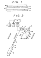
- Figure 1 shows a support medium for resolution and a stimulable phosphor sheet in a superposed form.
- Figure 2 schematically shows an embodiment of the read-out system for reading out the locational information on the radioactively labeled substances in a support medium, which is stored and recorded in the stimulable phosphor sheet according to the present invention.
- the stimulable phosphor sheet used in the present invention basically comprises a support and at least one phosphor layer, and the phosphor layer comprises a binder and a stimulable phosphor dispersed therein. Further, a transparent protective film is generally provided on the free surface (surface not facing the support) of the phosphor layer to keep the phosphor layer from chemical deterioration or physical shock.
- the stimulable phosphor sheet of such constitutuion can be prepared, for instance, by the following procedure.
- a material of the support of the stimulable phosphor sheet can be selected from those employed in conventional radiographic intensifying screens or those employed in known stimulable phosphor sheets.
- the support material include plastic films such as films of cellulose acetate and polyethylene terephthalate, a metal sheet such as aluminum foil, paper sheets such as an ordinary paper, baryta paper and resin-coated paper, or the like.
- On the surface of the support to receive the phosphor layer may be provided one or more of an adhesive layer, a light-reflecting layer, a light-absorbing layer, etc.
- the phosphor layer-side surface of the support (or the surface of an adhesive layer, light-reflecting layer or light-absorbing layer in the case where such layers provided on the phosphor layer) may be provided with protruded and depressed portions, as described in U.S. Patent Application No. 496,278 and European Patent Publication No. 92241.
- the phosphor layer comprises basically a binder and stimulable phosphor particles dispersed therein.
- the stimulable phosphor gives stimulated emission when excited with stimulating rays after exposure to a radiation.
- the stimulable phosphor is desired to give stimulated emission in the wavelength region of 300 - 500 nm when excited by stimulating rays in the wavelength region of 400 - 900 nm.
- Preferably employed in the invention is an europium activated alkaline earth metal fluorohalide phosphor, but any other stimulable phosphor can be employed in the invention.
- Examples of the stimulable phosphor include: SrS:Ce,Sm, SrS:Eu,Sm, Th0 2 :Er, and La 2 0 2 S:Eu,Sm, as described in U.S. Patent No. 3,859,527;
- ZnS:Cu,Pb, BaO ⁇ xAl 2 O 3 :Eu in which x is a number satisfying the condition of 0.8 ⁇ x ⁇ 10, and M 2+ O ⁇ xSi0 2 :A, in which M 2+ is at least one divalent metal selected from the group consisting of Mg, Ca, Sr, Zn, Cd and Ba, A is at least one element selected from the group consisting of Ce, Tb, Eu, Tm, Pb, Tl, Bi and Mn, and x is a number satisfying the condition of 0.5 ⁇ x ⁇ 2.5, as described in U.S. Patent No. 4,326,078;
- LnOX:xA in which Ln is at least one element selected from the group consisting of La, Y, Gd and Lu, X is at least one element selected from the group consisting of Cl and Br, A is at least one element selected from the group consisting of Ce and Tb, and x is a number satisfying the condition of 0 ⁇ x ⁇ 0.1, as described in the above-mentioned U.S. Patent No. 4,236,078; and
- M II is at least one divalent metal selected from the group consisting of Mg, Ca, Sr, Zn and Cd
- X is at least one element selected from the group consisting of CR, Br and I
- A is at least one element selected from the group consisting of Eu, Tb, Ce, Tm, Dy, Pr, Ho, Nd, Yb and Er
- x and y are numbers satisfying the conditions of 0 ⁇ x ⁇ 0.6 and 0 ⁇ y ⁇ 0.2, respectively, as described in U.S. Patent No. 4,239,968.
- phosphor particles and a binder are added to an appropriate solvent (e.g., a lower alcohol, chlorine atom-containing hydrocarbon, ketone, ester, ether), and then they are well mixed to prepare a coating dispersion comprising the phosphor particles dispersed in the binder solution.
- an appropriate solvent e.g., a lower alcohol, chlorine atom-containing hydrocarbon, ketone, ester, ether
- binder examples include proteins such as gelatin and synthetic polymers such as polyvinyl acetate, nitrocellulose, polyurethane, polyvinyl alcohol, linear polyester and polyalkyl (meth)acrylate.
- the ratio between the binder and the phosphor in the coating'dispersion generally is within the range of from 1 : 8 to 1 : 40 (binder : phosphor, by weight).
- the coating dispersion is then coated evenly on a support to form a coating layer, and the coating layer is gradually heated to dryness to prepare the phosphor layer on the support.
- the thickness of the phosphor layer generally ranges from 50 to 500 um.
- a transparent protective film may be provided to protect the phosphor layer from physical and chemical deterioration.
- the material of the protective film include cellulose acetate, polymethyl methacrylate, polyethylene terephthalate and polyethylene.
- the thickness of the transparent protective film generally ranges from 0.1 to 20 ⁇ m.
- the surface of the stimulable phosphor sheet on which a support medium is superposed may be previously subjected to any of various surface treatments to increase the adhesion between the phosphor sheet and the support medium.
- the protective film-side surface (or the support-side surface) may be previously subjected to surface activation treatment such as a glow discharge treatment or a roughing treatment to impart hydrophilic property thereto. Examples of the hydrophi- lically treated stimulable phosphor sheet is described in U.S. Patent Application No. 582,767 and European Patent Application No. 84101963.1.
- the support medium for resolving (or developing) a radioactively labeled substances originating from an organism can be selected from those employed or proposed to employ in the conventional autoradiography.
- Representative examples of the support medium include a medium for electrophoresis such as a gel support e.g., polyacrylamide gel; a medium for paper chromatography such as a filter paper; and a medium for thin layer chromatography such as silica gel.
- the support medium is generally subjected to the exposure operation in a dry state, but it may be used in a wet state such as containing a resolving solvent, if desired. Further, the support medium can be encased or supported by an accessory means such as glass plate or plastic sheet.
- the resolving support medium may be originally provided on the stimulable phosphor sheet to give an integrated structure.
- the intensity of a radiation (such as a-rays, a-rays or the like) radiating from the radioactively labeled substances is so low that the support medium is generally provided directly on the surface of the phosphor layer (or the surface of the protective film when used) of the stimulable phosphor sheet.
- kits for the autoradiographic process comprising the support medium for resolution and the stimulable phosphor sheet as described above are described more in detail in the aforementioned U.S. Patent Application No. 549,417 and European Patent Application No. 83110984.8.
- Examples of the sample to be resolved in the present invention include radioactively labeled organism-originating substances such as biopolymers, for instance, proteins, nucleic acids, their derivatives, their cleavage products, and their synthetic products.
- the organism-originating substances to be applied to the process of the invention are by no means restricted to the biopolymers as described above.
- the radioactivity label can be attached to the sample by introducing thereinto a radioactive element by appropriate means. Any radioactive element can be employed in the invention, provided that the radioactive element emits a radiation such as a-rays, S-rays, y-rays, neutron beams and X-rays.
- Typical examples of the radioactive elements include 32P, 14 C , 35 S, 3 H, and 125 I.
- the exposure operation is then carried out by placing the stimulable phosphor sheet and the support medium having the radioactively labeled substances resolved thereon together in layers in a dark room or in a light-shielded box for a certain period of time. Since the intensity of a radiation radiating from the labeled substances in the support medium is usually low, the phosphor sheet and the support medium can be superposed so as to bring the surface of the phosphor layer (or the surface of the protective film) into contact with the support medium as shown in Figure 1.
- Figure 1 is a schematic view showing a form in which the support medium for resolution and the stimulable phosphor sheet are combined together in layers (or superposed), in which numeral 1a represents the stimulable phosphor sheet comprising the support (a 1 ), the phosphor layer (a 2 ) and the protective film (a3), and numeral 1b represents the support medium for resolution.
- the support medium may be superposed on the support-side surface the stimulable phosphor sheet.
- the support medium and the stimulable phosphor sheet are so fixed not to slip off from each other.
- either or both of the support medium and the stimulable phosphor sheet may be mechanically processed so that they are fixed to each other in layers.
- the support medium and the stimulable phosphor sheet are held by transparent glass plates to fix each other.
- an autoradiograph is recorded as a radiation energy-stored image on the phosphor sheet.
- the exposure can be performed therein after the support medium and the phosphor sheet are combined together in layers even in a light room as described hereinafter.
- the exposure time varies depending on the radiation intensity of the radioactively labeled substance contained in the support medium, the amount of said substances and the sensitivity of the stimulable phosphor sheet.
- the exposure time can be greatly shortened as compared with that required in the case using the conventional radiographic film.
- the precise control of the exposure time is not particularly required, since the locational information on the radioactively labeled substances can be suitably processed in the subsequent read-out operation through applying various electrical processing thereto according to the intensity and distribution of energy stored in the phosphor sheet and the desired information form, for example, by setting the amplification of electric signals to an appropriate value.
- the temperature employed for the exposure operation there is no specific limitation on the temperature employed for the exposure operation, and it is possible to perform the exposure at an ambient temperature within the range of 10 to 35°C in the autoradiography according to the present invention. If desired, the exposure operation may be, of course, performed at a low temperature of approximately 5°C or lower as in the conventional autoradiography.
- the radiation energy stored in the phosphor sheet in the course of resolution of a sample on the support medium is released as light emission by irradiating the phosphor sheet with appropriate light or heat rays. More in detail, since the stimulable phosphor sheet is exposed to the natural radioactivity contained in a sample and to a radiation from the running radioactively labeled substances during the resolution, the radiation energy-stored image different from that to be read out (image showing the desired autoradiograph) is formed on the phosphor sheet to introduce a noise into the desired radiation energy-stored image. Thus, when the influence of the noise on the autoradiograph is not ignorable, it is desired to erase the noise before the radiation energy-stored image having the desired autoradiograph is formed on the stimulable phosphor sheet.
- the support medium having the sample resolved thereon as such or after optionally applying thereto a drying treatment or a resolved substance-fixing treatment may be subjected to the noise-erasing operation.
- the read-out operation for the autoradiograph stored and recorded in the stimulable phosphor sheet is performed.
- the phosphor sheet combined together with the support medium in layers (in the superposed form) is subjected as such to the read-out operation.
- Figure 2 schematically shows an embodiment of the read-out system for reading out the information on one or two dimensional location of the radioactively labeled substances, which is stored and recorded in the support medium-superposed stimulable phosphor sheet 1 shown in Figure 1 wherein numeral 1a represents the stimulable phosphor sheet and 1b represents the support medium.
- the read-out operation is carried out in the following manner.
- Laser beam 3 generated by a laser source 2 first passes through a filter 4 to cut off a light beam in the wavelength region corresponding to the wavelength region of stimulated emission to be emitted from the phosphor sheet la in response to stimulation with the laser beam 2.
- the size of the beam diameter of the laser beam 2 passed through the filter 4 is strictly controlled by means of a beam expander 5.
- the laser beam is subsequently deflected by a beam deflecter 6 such as a galvanometer mirror and reflected by a plane reflection mirror 7.
- the deflected beam then impinges one-dimensionally upon the support medium 1b of the support medium-superposed stimulable phosphor sheet 1.
- An f4 lens 8 is provided between the beam deflector 6 and the plane reflection mirror 7 so that the beam speed is continuously kept constant when the deflected laser beam is scanned on the support medium 1b.
- the laser source 2 used herein is so selected as to avoid overlapping of the wavelength region of the laser beam 4 with the main wavelength region of the stimulated emission to be given by the stimulable phosphor sheet 1a.
- the support medium-superposed phosphor sheet 1 is then transferred to the direction along the arrow 9 under the irradiation of the above-mentioned deflected laser beam. Therefore, the whole surface of the stimulable phosphor sheet 1a is subjected to the irradiation of the deflected laser beam through the support medium 1b.
- the phosphor sheet 1a When irradiated with the above-mentioned laser beam, the phosphor sheet 1a gives stimulated emission having the intensity proportional to the radiation energy stored therein.
- the emission then enters through the support medium 1b into a light guiding sheet 10.
- the light guiding sheet 10 has a linear edge face for receiving the emission and the edge face is so positioned in the vicinity of the support medium as to correspond to the scanning line on the support medium 1b.
- the exit of the light guiding sheet 10 is in the form of a ring and is connected to an light-receiving face of a photosensor 11 such as a photomultiplier.
- the light guiding sheet 10 is made, for instance, by processing a sheet of a transparent thermoplastic resin such as a synthetic acrylic resin, and so constituted that the emission introduced from the linear edge face is transferred to the exit under total reflection within the sheet 10.
- the stimulated emission from the phosphor sheet 1a is guided in the interior of the light guiding sheet 10 to the exit, and received by the photosensor 11.
- a filter which allows only the light in the wavelength region of the stimulated emission to pass therethrough and cuts off the light in the wavelength region of the stimulating rays (laser beam) so as to detect only the stimulated emission.
- the stimulated emission detected by the photosensor 11 is converted to electric signals, amplified to electric signals adjusted to an appropriate level in an amplifier 13 according to an amplification degree setting value a provided from a control circuit 12 and transmitted to an A/D converter 14.
- the adjusted electric signals are then converted to digital signals according to an appropriate scale factor defined by a scale factor setting value b provided from the same control circuit 12, and supplied to a signal processing circuit 15.
- the digital signals are so processed according to the image processing condition setting value c provided from the same control circuit 12 as to give a well-readable image having well adjusted concentration and contrast, and then transmitted to a recording device (not shown), optionally upon storage in a storing means such as a magnetic tape.
- the amplification degree setting value a, the scale factor setting value b and the image processing condition setting value c provided from the control circuit 12 can be set, for instance, according to the stored and recorded information obtained by carrying out a preliminary read-out operation prior to the above read-out operation so that a well-readable image having even concentration and contrast can be obtained.
- the setting values can be experimentally set according to the exposure time of the phosphor sheet.
- the locational information on the radioactively labeled substances can be obtained by detecting the resolved direction of bands (for instance, electrophoretic bands) of the radioactively labeled substances in the preliminary read-out operation and then carrying out the final read-out operation along the detected resolved direction as described in Japanese Patent Application No. 58(1983)-57417 (corresponding to U.S. Patent Application No. 595,479 or European Patent Application No. 84103619.7).
- bands for instance, electrophoretic bands
- Various recording devices based on various systems can be employed for the above-described purpose, for instance, a device for visualizing optically by scanning a photosensitive material with a laser beam, etc., a display means for visualizing electrically on CRT, etc., a means for printing a radiation image displayed on CRT by means of video printer, and a means for visualizing on a heatsensitive recording material using thermic rays.
- the manner of recording is not restricted to the manner of visualizing the image on the above-mentioned devices, and the information on the two dimensional location of the radioactively labeled substances can be recorded, for example, in the form of numerals and/or symbols.
- the support medium-superposed stimulable phosphor sheet may be irradiated with the stimulating rays on the phosphor sheet-side (namely, the support-side) and the stimulated emission also may be detected therefrom, instead of the irradiation and detection on the support medium-side as described above.
- the read-out system When the read-out system is made to be shielded from light, it is possible to perform the exposure in the system. Thus, there is no need of using a light-shielded box for the exposure.
- the erasure section for eliminating the noise is provided in the read-out system, it is not necessary to place the support medium and the stimulable phosphor sheet in layers just before the exposure operation (namely, setting them into the read-out system) and the superposition can be done in any suitable stage after resolving the sample. Further, it is possible to automate all the operations for the erasure, exposure and read-out under controlling the periods of time for the exposure and erasure in the read-out system.
- the autoradiographic process can be simplified to substantially comprise the resolving stage and the read-out stage including the exposure.
- the support medium and stimulable phosphor sheet are previously integrated, the superposition and separation thereof are not needed so that the read-out operation can be directly carried out after the resolution operation.
- the locational information on the radioactively labeled substances can be obtained in the desired form such as an image, symbols and/or numerals.
- the kit used in the following example comprises a stimulable phosphor sheet and a support medium for electrophoresis provided thereon, which was prepared by the following method.
- the coating dispersion was applied to a polyethylene terephthalate sheet (support, thickness: 250 gm) placed horizontally on a glass plate.
- the application of the coating dispersion was carried out using a doctor blade.
- the support having a layer of the coating dispersion was then placed in an oven and heated at a temperature gradually rising from 25 to 100°C. Thus, a phosphor layer having thickness of 300 ⁇ m was formed on the support.
- a polyethylene terephthalate transparent film (thickness: 12 ⁇ m; provided with a polyester adhesive layer on one surface) to combine the film and the phosphor layer with the adhesive layer.
- a stimulable phosphor sheet comprising a support, a phosphor layer and a protective film was prepared.
- the protective film-side surface of the phosphor sheet was treated with glow discharge by allowing the sheet to run at 15 cm distant from an electrode plate on which four half-circular rod electrodes (diameter: 2 cm, length: 40 cm) were fixed in each distance of 10 cm on an insulating plate, in a vacuum tank at pressure of 0.05 mmHg under the conditions of the discharge voltage of 3 kV, the treatment time of 3 sec. and the electrode current of 0.4 A.
- a polyethylene terephthalate film (thickness: 100 ⁇ m) was subjected to the glow discharge treatment on one surface in the same manner as described above and supported by a glass plate provided on the other surface to prepare a covering material for an electrophoretic support medium.
- Poly(methyl methacrylate) rectangular spacers were put between the covering material and the stimulable phosphor sheet, facing each other with the glow discharge-treated surfaces to prepare a mold for forming a suppot medium.
- a tris - borate buffer solution of acrylamide (acrylamide content: 8 %, crosslinking agent content: 3 %) prepared by the known method was poured into the mold to form a slab gel (1.5 mm x 200 mm x 200 mm).
- an integlated kit consisting of a stimulable phosphor sheet, a gel (electrophoretic support medium) and a polyethylene terephthalate film (covering material).
- Plasmid DNA of E. coli. (pBR 322) was cleaved by the use of restriction enzyme Hind-III by the known method and 5'-end thereof was labeled with 32 P to obtain 1 ⁇ g. of a double helix DNA ( 32 P-labeled substance).
- the double helix DNA (1 ⁇ g.) and approx. 1 unit of the restriction enzyme Hae-III were added to 20 ⁇ l. of 20 mM of tris[tris(hydroxymethyl) aminomethane] - hydrochloric acid buffer solution (pH 7.4) containing 5 mM of magnesium chloride and 1 mM of dithiothreitol.
- the resulting mixture was kept at 37 0 C for one hour to perform the specific cleavage reaction and a cleaved mixture solution containing cleavage products was obtained.
- the sample of cleaved mixture solution was charged on the slab gel support of the kit and electrophoresed at voltage of 500 V using 50 mM tris - borate buffer solution (pH 8.3) containing 1 mM of EDTA as an electrode solution.
- the electrophoresis was continued until the marker dye previously added to the sample reached the bottom end of the gel, and the starting position thereof was marked with a 32 P-containing ink.
- the kit was exposed to light to erase a noise recorded on the stimulable phosphor sheet.
- the kit was introduced into a read-out apparatus as shown in Figure 2 and kept at room temperature (approx. 25 0 C) for one minute to perform the exposure, and then read out to obtain locational information which represented electrophoretic positions of the fragments (cleavage products) labeled with 32P based on the starting position marked with the 32 P-containing ink.
- the slab gel support was separated together with the covering material from the kit. According to thus obtained locational information, the portions containing the fragments with 32P label were cut out of the gel with a thin razor blade, and the gel portion segments were placed in a test tube.
- the residual gel (a part of which had been removed as above) was laid again on the stimulable phosphor sheet, and the read-out operation was carried out thereto in the read-out apparatus to examine absence of the 32 P-labeled fragment.
- the result of the examination indicated that the 32 P-labeled fragments had been completely removed from the gel.
- the accuracy of the locational information on 32 P-labeled fragments obtained by means of the above stimulable phosphor sheet provided with the support medium was sufficiently high.
Landscapes
- Physics & Mathematics (AREA)
- Health & Medical Sciences (AREA)
- Life Sciences & Earth Sciences (AREA)
- General Physics & Mathematics (AREA)
- High Energy & Nuclear Physics (AREA)
- Molecular Biology (AREA)
- Spectroscopy & Molecular Physics (AREA)
- Measurement Of Radiation (AREA)
- Conversion Of X-Rays Into Visible Images (AREA)
- Investigating Or Analysing Biological Materials (AREA)
- Radiography Using Non-Light Waves (AREA)
Applications Claiming Priority (2)
| Application Number | Priority Date | Filing Date | Title |
|---|---|---|---|
| JP50292/84 | 1984-03-15 | ||
| JP59050292A JPS60194385A (ja) | 1984-03-15 | 1984-03-15 | オ−トラジオグラフ測定法 |
Publications (2)
| Publication Number | Publication Date |
|---|---|
| EP0159523A1 true EP0159523A1 (de) | 1985-10-30 |
| EP0159523B1 EP0159523B1 (de) | 1990-06-13 |
Family
ID=12854831
Family Applications (1)
| Application Number | Title | Priority Date | Filing Date |
|---|---|---|---|
| EP19850103029 Expired EP0159523B1 (de) | 1984-03-15 | 1985-03-15 | Verfahren zur Autoradiographie |
Country Status (3)
| Country | Link |
|---|---|
| EP (1) | EP0159523B1 (de) |
| JP (1) | JPS60194385A (de) |
| DE (1) | DE3578227D1 (de) |
Cited By (7)
| Publication number | Priority date | Publication date | Assignee | Title |
|---|---|---|---|---|
| US4931643A (en) * | 1987-11-17 | 1990-06-05 | Siemens Aktiengesellschaft | Autoradiography system for stimulable phosphor foils |
| EP0413962A1 (de) * | 1988-04-21 | 1991-02-27 | Quantex Corporation | Bilderzeugender Schirm für die Elektrophorese und Vorrichtung zur Bildwiedergabe |
| US5028793A (en) * | 1985-10-10 | 1991-07-02 | Quantex Corporation | Imaging screen for electrophoresis applications |
| WO1992005427A1 (en) * | 1990-09-25 | 1992-04-02 | Jydsk Telefon A/S | Method and device for the scanning of the distribution of sources of radiation in a medium, for example the distribution of proteins in a gel |
| EP0772059A1 (de) * | 1995-11-01 | 1997-05-07 | Eastman Kodak Company | Montage für Autoradiographie mit einem Lichtdurchlässigen Schirm |
| US6066858A (en) * | 1992-09-03 | 2000-05-23 | Fuji Photo Film Co., Ltd. | Autoradiographic process |
| GB2366370A (en) * | 2000-08-25 | 2002-03-06 | Amersham Pharm Biotech Uk Ltd | Reagent for scintillation proximity assays |
Families Citing this family (1)
| Publication number | Priority date | Publication date | Assignee | Title |
|---|---|---|---|---|
| CN111562278A (zh) * | 2020-05-22 | 2020-08-21 | 江苏万略医药科技有限公司 | 一种定量全身放射自显影药物分布跟踪方法 |
Citations (3)
| Publication number | Priority date | Publication date | Assignee | Title |
|---|---|---|---|---|
| US4236078A (en) * | 1978-07-12 | 1980-11-25 | Fuji Photo Film Co., Ltd. | Method and apparatus for recording and reproducing a radiation image |
| US4389670A (en) * | 1981-12-30 | 1983-06-21 | The United States Of America As Represented By The United States Department Of Energy | Electronic method for autofluorography of macromolecules on two-D matrices |
| EP0111154A2 (de) * | 1982-11-05 | 1984-06-20 | Fuji Photo Film Co., Ltd. | Verfahren zur Autoradiographie |
Family Cites Families (1)
| Publication number | Priority date | Publication date | Assignee | Title |
|---|---|---|---|---|
| JPS4877679U (de) * | 1971-12-25 | 1973-09-25 |
-
1984
- 1984-03-15 JP JP59050292A patent/JPS60194385A/ja active Pending
-
1985
- 1985-03-15 DE DE8585103029T patent/DE3578227D1/de not_active Expired - Lifetime
- 1985-03-15 EP EP19850103029 patent/EP0159523B1/de not_active Expired
Patent Citations (4)
| Publication number | Priority date | Publication date | Assignee | Title |
|---|---|---|---|---|
| US4236078A (en) * | 1978-07-12 | 1980-11-25 | Fuji Photo Film Co., Ltd. | Method and apparatus for recording and reproducing a radiation image |
| US4236078B1 (de) * | 1978-07-12 | 1989-01-03 | ||
| US4389670A (en) * | 1981-12-30 | 1983-06-21 | The United States Of America As Represented By The United States Department Of Energy | Electronic method for autofluorography of macromolecules on two-D matrices |
| EP0111154A2 (de) * | 1982-11-05 | 1984-06-20 | Fuji Photo Film Co., Ltd. | Verfahren zur Autoradiographie |
Non-Patent Citations (1)
| Title |
|---|
| NATURE, vol. 274, no. 5666, 6th July 1978, pages 87-89, Macmillan Journals Ltd., Basingstoke, GB; J. STANLEY et al.: "A different approach to RNA sequencing" * |
Cited By (9)
| Publication number | Priority date | Publication date | Assignee | Title |
|---|---|---|---|---|
| US5028793A (en) * | 1985-10-10 | 1991-07-02 | Quantex Corporation | Imaging screen for electrophoresis applications |
| US4931643A (en) * | 1987-11-17 | 1990-06-05 | Siemens Aktiengesellschaft | Autoradiography system for stimulable phosphor foils |
| EP0413962A1 (de) * | 1988-04-21 | 1991-02-27 | Quantex Corporation | Bilderzeugender Schirm für die Elektrophorese und Vorrichtung zur Bildwiedergabe |
| WO1992005427A1 (en) * | 1990-09-25 | 1992-04-02 | Jydsk Telefon A/S | Method and device for the scanning of the distribution of sources of radiation in a medium, for example the distribution of proteins in a gel |
| US6066858A (en) * | 1992-09-03 | 2000-05-23 | Fuji Photo Film Co., Ltd. | Autoradiographic process |
| EP0772059A1 (de) * | 1995-11-01 | 1997-05-07 | Eastman Kodak Company | Montage für Autoradiographie mit einem Lichtdurchlässigen Schirm |
| US5830629A (en) * | 1995-11-01 | 1998-11-03 | Eastman Kodak Company | Autoradiography assemblage using transparent screen |
| GB2366370A (en) * | 2000-08-25 | 2002-03-06 | Amersham Pharm Biotech Uk Ltd | Reagent for scintillation proximity assays |
| GB2366370B (en) * | 2000-08-25 | 2004-11-24 | Amersham Pharm Biotech Uk Ltd | Reagent for scintillation proximity assays |
Also Published As
| Publication number | Publication date |
|---|---|
| JPS60194385A (ja) | 1985-10-02 |
| EP0159523B1 (de) | 1990-06-13 |
| DE3578227D1 (de) | 1990-07-19 |
Similar Documents
| Publication | Publication Date | Title |
|---|---|---|
| US4617468A (en) | Stimulable phosphor sheet with hydrophilic surface | |
| US5260190A (en) | Autoradiographic process | |
| US4865967A (en) | Autoradiographic gene-screening method | |
| US5270162A (en) | Autoradiographic gene-screening method | |
| EP0160939B1 (de) | Autoradiographisches Verfahren | |
| EP0159523B1 (de) | Verfahren zur Autoradiographie | |
| US4888695A (en) | Signal processing method in autoradiography | |
| EP0725278B1 (de) | Verfahren zum Nachweis mittels Chemilumineszenz und Vorrichtung dafür | |
| EP0141382B1 (de) | Verfahren zur Bestimmung der Basensequenz der DNS oder der DNS-Fragmente mittels Autoradiographie | |
| EP0111154B1 (de) | Verfahren zur Autoradiographie | |
| EP0138086B1 (de) | Methode zum autoradiographischen Genscreening | |
| EP0115777B1 (de) | Verfahren zur Bestimmung der Basensequenz der DNS oder des DNS-Fragments | |
| US4871913A (en) | Signal processing method in autoradiography | |
| JPH0160784B2 (de) | ||
| JPH0456259B2 (de) | ||
| US6066858A (en) | Autoradiographic process | |
| JPS60233582A (ja) | オ−トラジオグラフ測定法 | |
| JPH0465997B2 (de) | ||
| JP2945547B2 (ja) | オートラジオグラム測定方法 | |
| JPH09281240A (ja) | オートラジオグラフィ露光装置 |
Legal Events
| Date | Code | Title | Description |
|---|---|---|---|
| PUAI | Public reference made under article 153(3) epc to a published international application that has entered the european phase |
Free format text: ORIGINAL CODE: 0009012 |
|
| AK | Designated contracting states |
Designated state(s): CH DE FR LI NL SE |
|
| 17P | Request for examination filed |
Effective date: 19851202 |
|
| 17Q | First examination report despatched |
Effective date: 19870508 |
|
| GRAA | (expected) grant |
Free format text: ORIGINAL CODE: 0009210 |
|
| AK | Designated contracting states |
Kind code of ref document: B1 Designated state(s): CH DE FR LI NL SE |
|
| REF | Corresponds to: |
Ref document number: 3578227 Country of ref document: DE Date of ref document: 19900719 |
|
| ET | Fr: translation filed | ||
| PLBE | No opposition filed within time limit |
Free format text: ORIGINAL CODE: 0009261 |
|
| STAA | Information on the status of an ep patent application or granted ep patent |
Free format text: STATUS: NO OPPOSITION FILED WITHIN TIME LIMIT |
|
| 26N | No opposition filed | ||
| EAL | Se: european patent in force in sweden |
Ref document number: 85103029.6 |
|
| PGFP | Annual fee paid to national office [announced via postgrant information from national office to epo] |
Ref country code: FR Payment date: 20040322 Year of fee payment: 20 |
|
| PGFP | Annual fee paid to national office [announced via postgrant information from national office to epo] |
Ref country code: NL Payment date: 20040323 Year of fee payment: 20 |
|
| PGFP | Annual fee paid to national office [announced via postgrant information from national office to epo] |
Ref country code: SE Payment date: 20040325 Year of fee payment: 20 |
|
| PGFP | Annual fee paid to national office [announced via postgrant information from national office to epo] |
Ref country code: CH Payment date: 20040326 Year of fee payment: 20 |
|
| PGFP | Annual fee paid to national office [announced via postgrant information from national office to epo] |
Ref country code: DE Payment date: 20040430 Year of fee payment: 20 |
|
| PG25 | Lapsed in a contracting state [announced via postgrant information from national office to epo] |
Ref country code: LI Free format text: LAPSE BECAUSE OF EXPIRATION OF PROTECTION Effective date: 20050314 Ref country code: CH Free format text: LAPSE BECAUSE OF EXPIRATION OF PROTECTION Effective date: 20050314 |
|
| PG25 | Lapsed in a contracting state [announced via postgrant information from national office to epo] |
Ref country code: NL Free format text: LAPSE BECAUSE OF EXPIRATION OF PROTECTION Effective date: 20050315 |
|
| REG | Reference to a national code |
Ref country code: CH Ref legal event code: PL |
|
| NLV7 | Nl: ceased due to reaching the maximum lifetime of a patent |
Effective date: 20050315 |
|
| EUG | Se: european patent has lapsed |