EP0159572A2 - Dispositif pour introduire de l'acier liquide dans des installations de coulée continue à double bande - Google Patents
Dispositif pour introduire de l'acier liquide dans des installations de coulée continue à double bande Download PDFInfo
- Publication number
- EP0159572A2 EP0159572A2 EP85103739A EP85103739A EP0159572A2 EP 0159572 A2 EP0159572 A2 EP 0159572A2 EP 85103739 A EP85103739 A EP 85103739A EP 85103739 A EP85103739 A EP 85103739A EP 0159572 A2 EP0159572 A2 EP 0159572A2
- Authority
- EP
- European Patent Office
- Prior art keywords
- tube
- sealing
- compensating
- sprue
- pipe
- Prior art date
- Legal status (The legal status is an assumption and is not a legal conclusion. Google has not performed a legal analysis and makes no representation as to the accuracy of the status listed.)
- Withdrawn
Links
Images




Classifications
-
- B—PERFORMING OPERATIONS; TRANSPORTING
- B22—CASTING; POWDER METALLURGY
- B22D—CASTING OF METALS; CASTING OF OTHER SUBSTANCES BY THE SAME PROCESSES OR DEVICES
- B22D11/00—Continuous casting of metals, i.e. casting in indefinite lengths
- B22D11/06—Continuous casting of metals, i.e. casting in indefinite lengths into moulds with travelling walls, e.g. with rolls, plates, belts, caterpillars
- B22D11/0637—Accessories therefor
- B22D11/064—Accessories therefor for supplying molten metal
- B22D11/0642—Nozzles
Definitions
- the invention relates to a feed device for introducing molten steel into double-belt casting machines with mold walls moved exclusively in the casting direction, with a cast-iron pipe which can be rotated about a horizontal pivot axis and which is laterally adjustable transversely to its longitudinal extent, and which has its own slide forms a pouring unit which is movable separately from a preceding front container and from the double belt casting machine, a sealing gap being able to be produced therewith via the pouring pipe mouthpiece projecting between the mold walls and the pouring pipe being connected to the movable, via a sealing surface which, as a ball socket or ball pin, is part of a ball joint, height-adjustable front container is connectable.
- the movable and orientable arrangement of the sprue tube allows it to be separated from the header tank and from the double belt casting machine, and makes it possible to heat the connecting parts accessible after the separation between the header tank and double belt casting machine by means of burners.
- the mouthpiece of the sprue tube given its ball-and-socket connection with the front container, can be aligned with respect to the mold space of the double-belt casting machine in such a way that it forms a sealing gap with the mold walls, which forms the outlet from Excludes steel melt between the mouthpiece and mold walls to the outside.
- the feeding device of the type mentioned at the outset is to be further developed in such a way that it works with the required operational reliability, regardless of any deformations that may occur on the interacting components.
- a temperature-related, unforeseeable shift of the end points of the mutually interacting sealing surfaces should not lead to the casting process possibly having to be stopped prematurely due to the escape of molten steel.
- the above-mentioned object is achieved in that the feed device of the type mentioned at the outset is further developed in the manner described in claim 1.
- the basic idea of the invention consists in the use of a compensating tube between the sprue tube and the header tank, which forms a movable sealing point not only in the region of its outlet with the sprue tube, but also in the region of its inlet with the header tank; one of the two sealing points is simultaneously designed as a coupling point of the sealing surfaces interacting there.
- a further movable sealing point between the sprue tube and the header tank, via which any deformations that occur during heating and cooling can be compensated for.
- the compensating tube forms a movable part of the sprue tube (claim 2), is preferably articulated to it (claim 3).
- the coupling point which enables mutual movements, exists at the inlet of the compensating pipe between the latter and the header tank. Displacements between the pouring pipe and the front container can be compensated to a greater extent by the fact that the sealing surfaces of the compensating pipe and the front container interacting at the inlet sealing point are designed as flat surfaces (claim 4). Due to the mobility of the ball joint at the outlet sealing point of the compensating tube, the two flat surfaces can each take a position in which they form a reliable sealing point that is independent of relocations.
- the compensating tube is designed as a spherical cap with a small longitudinal extension (claim 5), that is to say it consists of a ball stud, which is directly adjoined on the entry side by the plane surface already mentioned.
- the compensating pipe equipped with a flat surface is preferably fastened to the sprue pipe via finger-like holding elements which engage with groove-shaped recesses in the compensating pipe (claim 6); the range of motion between the finger-like holding elements and the groove-shaped recesses is dimensioned such that the compensating tube can be pivoted in the required angular range with respect to the sprue tube.
- the inlet sealing point of the compensating tube is also composed of sealing surfaces which together form a ball joint (claim 7). Due to the use of two ball joints, the compensating pipe can compensate for any displacement occurring between the pouring pipe and the header tank, without fear of leaks in the area of the two sealing points.
- the compensating tube (which normally has a greater longitudinal extension than the spherical cap according to claim 5) is adjustable in height with respect to the front container on a support element which in turn is held on the slide of the sprue tube (claim 8).
- the support element is expediently designed so that it is the compensating tube in each case holds in the desired altitude.
- the compensating tube can be suspended from a cable that is equipped with a counterweight that serves to balance the weight.
- the compensating tube has a side adjustment unit, by means of which its side position with respect to the front container can be changed (claim 9).
- a particularly simple design of the side adjustment unit is a cable pulling on the compensating tube, which is supported on the surroundings via deflection rollers (i.e. on the sprue tube and / or the slide).
- the compensating tube or the front container is preferably covered with a fiber mat which essentially consists of A1 2 0 3 and Si0 2 (claim 10).
- the feed device having a sprue pipe 1 works together with an upstream front container 2, the melting space 4 delimited by a side wall 3 merging downwards into a deflection stone 5.
- An operationally reliable connection is to be made between this and the sprue pipe 1, which will be explained in detail later.
- the supply of molten steel from the front container 2 can be influenced by means of a height-adjustable stopper rod 6 arranged in the region of the deflection stone 5.
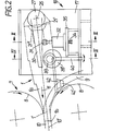
- the sprue pipe 1 is equipped on its side facing a double belt casting machine 7 with a mouthpiece 1a, which with its front section and its outlet section 1b protrudes to form a layer D gap between the mold walls 8, 9 (vgl.Fig.1 and 2). These delimit a rectangular mold space 10 and circulate in the region of the casting direction (arrow 11) accordingly.
- the mold space like the pouring tube 1, is inclined at an angle of 6 ° with respect to the horizontal in order to be able to empty the double belt casting machine 7.
- the mold walls of the double belt casting machine consist of paired opposite (upper and lower) endless casting belts 8 and laterally (shown in FIG. 2) on these adjoining endless, structured side dams 9.
- the front container 2 is releasably attached to a vehicle 12, the wheel sets 13 of which are equipped with eccentric bushings, not shown, and can be adjusted in height with respect to the vehicle frame 14, indicated by a double arrow 14 '.
- the vehicle 12 can be moved along a guideway 15 in the sense of the double arrow 16 by means of a displacement drive, for example in the form of an articulated hydraulic cylinder.
- the sprue tube 1 is movably held on a carriage 18 via a housing 17, which in turn is supported on a fixed guide, movable in both directions; this essentially consists of a guide rod 19 and a guide frame 20 supporting it (cf. FIG. 1).
- the pouring pipe 1 with the longitudinal axis 1 '- which in the area of the slide 18 as essential components a ceramic inner lining 21 with a casting bore 22, a heat insulating layer 23 surrounding the inner lining and a steel jacket 24 serving as a supporting element
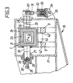
- the pivot pin 26 of the pivot axis 25 (located on the left in FIG. 3) is provided outside the area of the associated bearing bush 27 with a rectangular groove 26 'into which the adjustment head 28' of a side adjustment screw 28 engages with lateral play. This is supported via its threaded section in an adjustment housing 29 connected to the bearing bush 27.
- the sprue tube 1, which is supported on the pivot axis 25, can be laterally displaced within the housing 17 and held roughly adjusted in the desired lateral position. This is important with regard to the orientation of the mouthpiece 1a (see FIG. 1) in the cold state with respect to the side dams 9 (see FIG. 2) which protrude over the casting belts 8 in the opposite direction to the pouring direction. There is approximately 1 millimeter of freedom of movement for hot alignment.
- this is laterally (cf. in particular FIG. 3) equipped with a rigidly attached rocker arm 30 which projects to the right over the housing 17 and which rests on an elastically supported buffer 31; this is movably supported in a housing 32 by a spring element in the form of a package 33 of disc springs.
- the pre 1 tension force of the spring element can be increased or decreased by means of a preload screw 34.
- the housing 32 is connected to the housing 17 via a side console 35.
- an inclination eccentric 36 is attached, the essential components of which are an immovable support arm 37, a bearing bush 38, an eccentric bushing 39 with an eccentric 39 'and a lever 40 which enables the adjustment of the inclination eccentric.
- the eccentric disk 39 ' can be brought into contact with the already mentioned rocker arm 30.
- the inclined position of the pouring tube 1 with respect to the housing 17 can be varied continuously over a wide range.
- the position of the eccentric bushing 39 with respect to the support arm 37 can be secured in a simple manner in that a locking screw 41 which extends through the parts 39 and 38 is braced against the support arm 37.
- the pouring tube of the feed device according to the invention thus has, in addition to the buffer 31, an inclination adjustment which facilitates the threading of the mouthpiece 1a between the mold walls 8 and 9.
- the position of the inclination eccentric 36 and the buffer 31 with respect to the housing 17 can be seen particularly well from FIG.
- the mouthpiece 1a protrudes in the pouring position into the mold space 10 at an angle of 6 °, the longitudinal axis 1 'of the pouring tube 1 coinciding with the longitudinal axis 10' of the mold space.
- the advantage of the described embodiment is that the pouring tube 1 can be brought in advance by swiveling the lever 40 into a position which enables the mouthpiece 1a to be threaded effortlessly.
- a metallic centering part 42 with finely machined, bevelled side surfaces 42 ' is attached below the pouring tube.
- the side surfaces 42 ′ reach the area of the projecting side dams 9 and bring the sprue tube 1 into the required lateral position, in which the centering part 42 finally lies between the mold walls 9.
- only the carriage 18 has to be moved in the direction of the double belt casting machine (i.e. to the left in FIG. 2).
- connection surface 21 'of the ceramic inner lining 21 facing the front container which also comprises a concave sealing surface 21 "designed as a ball socket, lies - seen in the casting direction (arrow 11) - behind the pivot axis 25 of the pouring tube 1.
- the fulcrum of the pouring tube 1, which is movable in the manner of a rocker, and the center of the ball of the ball joint to be described, which center is assigned to the sealing surface 21 ", are identical to one another.
- a releasable connection between the pouring pipe 1 and the front container can be produced via a short compensating tube 43 designed as a spherical cap, the pouring channel 5 of which merges into a ceramic stone 45 fastened via sealing mortar 44 with a pouring hole 45 ' .
- the spherical cap 43 is supported via its convexly curved outer surface 43 'on a sealing surface 46 consisting of a fiber mat, which is concave on the curved sealing surface 21 ".
- the two interacting sealing surfaces 43 'and 21" thus form an outlet sealing point located at the outlet of the compensating tube 43 in the manner of a ball joint.
- the connecting section 1c preceding the connecting surface 21 ' is equipped with screw-type connections 47 with finger-like holding elements 48 which engage with groove-shaped recesses 43 "in the compensating pipe 43 and prevent its separation from the sprue pipe.
- the opposite end faces of the compensating tube 43 and the ceramic stone 45 are each designed as flat faces 43 ′′ or 45 ′′, the former being covered with a fiber mat 49 serving as a sealing face.
- a further sealing point can be formed via the two cooperating sealing surfaces 43 "'and 45" at the entry of the equalizing tube 43, which in this respect temperature-related displacements between the pouring tube 1 and the Attachment container 2 allows when it is built up from flat surfaces.
- the ball joint forming the outlet sealing point ensures that the flat surface 43 ′′ with the fiber mat 49 can in each case adapt to the position of the sealing surface 45 ′′ of the ceramic stone 45.
- the compensating tube 43 is tracked via the holding elements 48 of the movement of the pinch tube 1; the inlet sealing point with the components 43 "', 49 and 45" thus simultaneously forms a coupling point.
- connection between the pouring pipe 1 (shown purely schematically) and the header tank 2 can be established via a compensating pipe 50 with a longitudinal extension of several 100 millimeters.
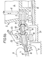
- the compensating pipe 50 which is movably held on the pouring pipe 1, forms with the connecting section 1c an outlet sealing point which, in accordance with the embodiment according to FIG. 5, is designed as a ball joint.
- the convex sealing surface 50 'designed as a ball pivot is supported by the interposition of a fiber mat 46 in the sealing surface 21' 'of the inner lining of the pouring tube 1.
- the center of rotation of the sealing surface 50' coincides with the pivot axis 25 of the pouring tube Attachment container 2 facing side (ie at the entrance to the compensating tube 50) there is a correspondingly designed convex sealing surface 50 ′′.
- This is opposite the concave sealing surface 51 ', which is designed as a ball socket, of a ceramic stone 51 fastened to the deflection stone 5 and which is covered with a fiber mat 52 (FIG. 6a).
- An inlet sealing point can be formed via the two sealing surfaces 50 "and 51 ', which, like the already described outlet sealing point with the sealing surfaces 21" and 50', represents a ball joint (FIGS. 6b and 7).
- the compensating tube 50 is expediently designed as a movable component of the pouring tube 1; the inlet sealing point between the compensating tube 50 and the ceramic stone 51 with the interacting sealing surfaces 50 ′′ and 51 ′ serves at the same time as a coupling point via which the components 1 and 2, for example for heating the sprue tube 1, the compensating tube 50, the ceramic stone 51 and the floor channel 5 , can be separated from each other and made accessible.
- the support on the sprue pipe 1 (cf. FIG. 6a) which permits adjustment of the height of the compensating pipe 50 is achieved in that the compensating pipe is additionally suspended on a cable 53 with a counterweight 54.
- the cable 53 is supported on a stand 55 with a deflection roller 56 on the carriage 18 of the sprue 1.
- the supporting element, which additionally supports the compensating tube, is expediently designed in such a way that the latter maintains a height position, once set, with respect to the ceramic stone 51 without external action.
- the threading process for producing the entry sealing point with the sealing surfaces 50 "and 51 '(see FIG. 7) can be further simplified in that the compensating tube 50 is additionally equipped with a side adjustment unit, via which the lateral position of the compensating tube with respect to the ceramic stone 51 and thus is changeable with respect to the front container 2.
- the compensating tube 50 is pivotally attached in both lateral directions to a side cable 57 which is supported on the housing 17 of the slide 18 for the sprue tube 1 via deflection rollers 58 and 59, respectively.
- the compensating tube 50 can be pivoted to the left or to the right and thus be aligned in its lateral position with respect to the ceramic stone 51.
- the front container 2 is moved to the right so far that the sealing surface 50 "is in the ceramic stone 51 threads and, by means of its sealing surfaces 50 'and 50 "against the fiber fabric 46 and 52, with the associated sealing surfaces of the pouring tube 1 and the ceramic stone 51, respectively, forms an outlet and inlet sealing point designed as a ball joint.
- the pouring process caused by temperature-related deformations of the parts connected via the compensating tube 50 as well as displacements in the vertical and lateral position can be compensated without disturbing the pouring process, because the connection between the sprue 1 and the header 2 is designed as a multiple joint.
- the sensitive alignment of the pouring tube 1 with respect to the mold walls 8 and 9 delimiting the mold space 10 is necessary because a sealing gap of the order of a few tenths of a millimeter must be maintained in the region of the mouthpiece 1a during the casting process. This is particularly important when the steel melt is cast under pressure to achieve a high-quality cast product.
- the molten bath level within the front container 2 is always at a height which lies above the outlet cross section 1b in the mold space 10. This die casting process assumes that the seal between the mouthpiece 1a and the mold walls withstands the increased metallostatic pressure in this area.
- the advantage achieved by the invention consists in the fact that a connection, designed as a multiple joint, between the pouring tube 1 and the front container 2
- the heat insulation layer 23 (cf. FIG. 3), via which the ceramic inner lining 21 resiliently supports the steel jacket 24, preferably consists of aluminum oxide fibers, aluminum silicate fibers and an organic binder (proportions: 72% A1 2 0 3 , 21 % Si0 2 , balance binder). Above a temperature of about 400 ° C, the binder changes to the gaseous state, so that the heat insulation layer then only consists of the components Al 2 O 3 and SiO 2 .
- the ceramic inner lining 21 (of the pouring tube 1) consists, apart from the mouthpiece 1a in the area of the mold walls, of amorphous silica (Si0 2 ) or alumina (Al 2 O 3 ); The same applies to the compensating tubes 43, 50 and the ceramic stones 45, 51 interacting with them (cf. FIGS. 5 and 6, 7).
- the mouthpiece 1a consists of boron nitride (BN) at least in the area in which it forms a narrow sealing gap with the mold walls 8, 9.
- the fiber mat 46 or 49 or 52 (cf. FIGS. 5 and 6, 7) is approximately 1.5 mm thick and is composed of the components A1 2 0 3 , SiO 2 and binder. It serves to compensate for manufacturing inaccuracies of the respective interacting sealing surfaces and thus to ensure the operational safety of the sealing points concerned.
Landscapes
- Engineering & Computer Science (AREA)
- Mechanical Engineering (AREA)
- Casting Support Devices, Ladles, And Melt Control Thereby (AREA)
- Continuous Casting (AREA)
Applications Claiming Priority (2)
| Application Number | Priority Date | Filing Date | Title |
|---|---|---|---|
| DE3415235A DE3415235C2 (de) | 1984-04-21 | 1984-04-21 | Zuführeinrichtung zum Einbringen von Stahlschmelze in Doppelbandgießmaschinen |
| DE3415235 | 1984-04-21 |
Publications (2)
| Publication Number | Publication Date |
|---|---|
| EP0159572A2 true EP0159572A2 (fr) | 1985-10-30 |
| EP0159572A3 EP0159572A3 (fr) | 1986-05-28 |
Family
ID=6234255
Family Applications (1)
| Application Number | Title | Priority Date | Filing Date |
|---|---|---|---|
| EP85103739A Withdrawn EP0159572A3 (fr) | 1984-04-21 | 1985-03-28 | Dispositif pour introduire de l'acier liquide dans des installations de coulée continue à double bande |
Country Status (4)
| Country | Link |
|---|---|
| US (1) | US4576218A (fr) |
| EP (1) | EP0159572A3 (fr) |
| JP (1) | JPS60234750A (fr) |
| DE (1) | DE3415235C2 (fr) |
Cited By (5)
| Publication number | Priority date | Publication date | Assignee | Title |
|---|---|---|---|---|
| EP0279522A3 (en) * | 1987-01-22 | 1988-09-07 | Ishikawajima-Harima Jukogyo Kabushiki Kaisha | Apparatus for pouring molten metal |
| EP0340769A1 (fr) * | 1988-05-05 | 1989-11-08 | Hazelett Strip-Casting Corporation | Procédé et dispositif pour préciser l'espace entre la busette de coulée et la bande de coulée ainsi que entre la busette de coulée et le bloc de rive |
| EP0346077A1 (fr) * | 1988-06-10 | 1989-12-13 | Ishikawajima-Harima Jukogyo Kabushiki Kaisha | Alignement de la busette de coulée d'une machine de coulée continue |
| EP0346076A1 (fr) * | 1988-06-08 | 1989-12-13 | Ishikawajima-Harima Jukogyo Kabushiki Kaisha | Machines pour la coulée continue |
| WO1990000455A3 (fr) * | 1988-07-13 | 1990-03-22 | Uss Eng & Consult | Systeme d'alimentation a tete basse pour le coulage de sections minces |
Families Citing this family (6)
| Publication number | Priority date | Publication date | Assignee | Title |
|---|---|---|---|---|
| FR2588939B1 (fr) * | 1985-10-18 | 1988-07-08 | Air Liquide | Dispositif de transfert d'un fluide cryogenique |
| US4738380A (en) * | 1986-02-28 | 1988-04-19 | Flo-Con Systems, Inc. | Self-adjusting refractory joint |
| WO2002102531A1 (fr) * | 2001-05-31 | 2002-12-27 | Disa Industries A/S | Assemblage de tube de remplissage destine a relier un moule a remplir de metal fondu et un four |
| US6418911B1 (en) | 2001-07-13 | 2002-07-16 | Siemens Diesel Systems Technology | Device and procedure for coupling a fluid rail with fuel injectors |
| US6565128B2 (en) | 2001-07-13 | 2003-05-20 | Siemens Diesel Systems Technology | Device and method for coupling a fluid rail with fuel injectors |
| DE10240512A1 (de) * | 2002-09-03 | 2004-03-11 | INDUGA Industrieöfen und Giesserei-Anlagen GmbH & Co. KG | Verfahren und Vorrichtung zum kontinuierlichen Gießen von Metallen |
Family Cites Families (6)
| Publication number | Priority date | Publication date | Assignee | Title |
|---|---|---|---|---|
| GB191515758A (en) * | 1914-11-28 | 1916-11-08 | Grenville Mellen | Improvements in Continuous Casting-machines. |
| GB908902A (en) * | 1960-02-24 | 1962-10-24 | United Steel Companies Ltd | Improvements relating to nozzles for continuously casting metals |
| US3478813A (en) * | 1967-06-05 | 1969-11-18 | Southwire Co | Vessel positioning means for continuous casting machines |
| FR2389433B1 (fr) * | 1977-05-06 | 1981-06-12 | Secim | |
| DE3009189B1 (de) * | 1980-03-11 | 1981-08-20 | Mannesmann Demag Ag, 4100 Duisburg | Verfahren zum Horizontalstranggiessen von fluessigen Metallen,insbesondere von Stahl,und Einrichtung dazu |
| DE3311090C2 (de) * | 1983-03-26 | 1985-04-04 | Fried. Krupp Gmbh, 4300 Essen | Zuführeinrichtung zum Einbringen von Stahlschmelze in Doppelbandgießmaschinen |
-
1984
- 1984-04-21 DE DE3415235A patent/DE3415235C2/de not_active Expired
-
1985
- 1985-03-28 EP EP85103739A patent/EP0159572A3/fr not_active Withdrawn
- 1985-04-19 US US06/724,809 patent/US4576218A/en not_active Expired - Fee Related
- 1985-04-22 JP JP60084696A patent/JPS60234750A/ja active Pending
Cited By (5)
| Publication number | Priority date | Publication date | Assignee | Title |
|---|---|---|---|---|
| EP0279522A3 (en) * | 1987-01-22 | 1988-09-07 | Ishikawajima-Harima Jukogyo Kabushiki Kaisha | Apparatus for pouring molten metal |
| EP0340769A1 (fr) * | 1988-05-05 | 1989-11-08 | Hazelett Strip-Casting Corporation | Procédé et dispositif pour préciser l'espace entre la busette de coulée et la bande de coulée ainsi que entre la busette de coulée et le bloc de rive |
| EP0346076A1 (fr) * | 1988-06-08 | 1989-12-13 | Ishikawajima-Harima Jukogyo Kabushiki Kaisha | Machines pour la coulée continue |
| EP0346077A1 (fr) * | 1988-06-10 | 1989-12-13 | Ishikawajima-Harima Jukogyo Kabushiki Kaisha | Alignement de la busette de coulée d'une machine de coulée continue |
| WO1990000455A3 (fr) * | 1988-07-13 | 1990-03-22 | Uss Eng & Consult | Systeme d'alimentation a tete basse pour le coulage de sections minces |
Also Published As
| Publication number | Publication date |
|---|---|
| JPS60234750A (ja) | 1985-11-21 |
| DE3415235A1 (de) | 1985-10-31 |
| DE3415235C2 (de) | 1986-04-03 |
| EP0159572A3 (fr) | 1986-05-28 |
| US4576218A (en) | 1986-03-18 |
Similar Documents
| Publication | Publication Date | Title |
|---|---|---|
| EP0159572A2 (fr) | Dispositif pour introduire de l'acier liquide dans des installations de coulée continue à double bande | |
| DE69227686T2 (de) | Druckgussmaschine | |
| EP0920937B1 (fr) | Lingotière pour la coulée continue | |
| DE2304875C2 (de) | Vorrichtung zum Einblasen von Heisswind in einen Schachtofen, insbesondere Hochofen | |
| EP0123121B1 (fr) | Installation de chargement pour alimenter en acier fondu des machines de coulée en continu dont les parois de lingotière se déplacent dans le mDme sens que la direction de coulée | |
| EP1843867A1 (fr) | Chariot doté d'un dispositif de levage pour canal de distribution | |
| EP0133896B1 (fr) | Chenal réfractaire assemblé pour la coulée continue horizontale | |
| EP0055210B1 (fr) | Dispositif et procédé de coulée sous basse pression | |
| DE2840171A1 (de) | Verschlussvorrichtung fuer den bodenausguss von giesspfannen | |
| DE3500863C2 (de) | Schiebeverschluß für den Ausguß metallurgischer Gefäße | |
| EP0241825B1 (fr) | Procédé et dispositif pour ajuster une lingotière de coulée continue | |
| EP0417504A2 (fr) | Coquille pour la coulée continue | |
| DE69802316T2 (de) | Brammen-Stranggiessmaschine mit Vorrichtung zum Auswechseln eines Tauchgiessrohres und Verfahren zum Auswechseln eines Tauchgiessrohres | |
| EP0033309B1 (fr) | Dispositif de protection pour un jet de coulée sortant d'un récipient métallurgique | |
| DE69707362T2 (de) | Träger für ein Überfangglaspostenstruktur und Bediensystem dafür | |
| EP0010728B1 (fr) | Installation de coulée continue avec une lingotière oscillante | |
| DE202006012268U1 (de) | Einspritzaggregat zum gesteuerten An- und Wegfahren des Spritzaggregates | |
| DE69001257T2 (de) | Druckgiesskokille fuer flachmetallprodukte, die brammen. | |
| AT407351B (de) | Stranggiesskokille | |
| CH680501A5 (fr) | ||
| DE69304703T3 (de) | Vorrichtung zur durchflussregelung eines flüssigen metallstromes | |
| DE2408894A1 (de) | Vorrichtung zum heben und schwenken eines metallurgischen gefaesses | |
| EP0156764A1 (fr) | Moule électromagnétique de coulée continue | |
| AT403773B (de) | Metallurgisches gefäss | |
| DE1783174C3 (de) | Verfahren und Hilfsvorrichtung für den Einbau und die Justierung der feuerfesten Einzelteile von regelbaren Bodenverschlüssen für Stahlgießpfannen |
Legal Events
| Date | Code | Title | Description |
|---|---|---|---|
| PUAI | Public reference made under article 153(3) epc to a published international application that has entered the european phase |
Free format text: ORIGINAL CODE: 0009012 |
|
| AK | Designated contracting states |
Designated state(s): AT BE CH FR GB IT LI LU NL SE |
|
| PUAL | Search report despatched |
Free format text: ORIGINAL CODE: 0009013 |
|
| AK | Designated contracting states |
Kind code of ref document: A3 Designated state(s): AT BE CH FR GB IT LI LU NL SE |
|
| STAA | Information on the status of an ep patent application or granted ep patent |
Free format text: STATUS: THE APPLICATION HAS BEEN WITHDRAWN |
|
| 18W | Application withdrawn |
Withdrawal date: 19861113 |
|
| R18W | Application withdrawn (corrected) |
Effective date: 19861113 |
|
| RIN1 | Information on inventor provided before grant (corrected) |
Inventor name: FIGGE, DIETER Inventor name: ARTZ, GERD Inventor name: PHILIPP, CLEMENS Inventor name: BECKMANN, GERHARD |