EP0159633B1 - Umkehrbares Zuführungssystem - Google Patents
Umkehrbares Zuführungssystem Download PDFInfo
- Publication number
- EP0159633B1 EP0159633B1 EP85104461A EP85104461A EP0159633B1 EP 0159633 B1 EP0159633 B1 EP 0159633B1 EP 85104461 A EP85104461 A EP 85104461A EP 85104461 A EP85104461 A EP 85104461A EP 0159633 B1 EP0159633 B1 EP 0159633B1
- Authority
- EP
- European Patent Office
- Prior art keywords
- line
- spool
- valve
- lubricant
- inlet
- Prior art date
- Legal status (The legal status is an assumption and is not a legal conclusion. Google has not performed a legal analysis and makes no representation as to the accuracy of the status listed.)
- Expired - Lifetime
Links
- 230000002441 reversible effect Effects 0.000 title description 3
- 239000000314 lubricant Substances 0.000 claims description 83
- 238000004891 communication Methods 0.000 description 26
- 125000004122 cyclic group Chemical group 0.000 description 11
- 230000000712 assembly Effects 0.000 description 9
- 238000000429 assembly Methods 0.000 description 9
- 238000005461 lubrication Methods 0.000 description 4
- 238000012986 modification Methods 0.000 description 4
- 230000004048 modification Effects 0.000 description 4
- 238000013519 translation Methods 0.000 description 3
- 230000004323 axial length Effects 0.000 description 1
- 238000010276 construction Methods 0.000 description 1
- 238000013461 design Methods 0.000 description 1
- 230000000694 effects Effects 0.000 description 1
- 239000012530 fluid Substances 0.000 description 1
- 239000000523 sample Substances 0.000 description 1
- 238000012163 sequencing technique Methods 0.000 description 1
- 238000012546 transfer Methods 0.000 description 1
Images


Classifications
-
- F—MECHANICAL ENGINEERING; LIGHTING; HEATING; WEAPONS; BLASTING
- F16—ENGINEERING ELEMENTS AND UNITS; GENERAL MEASURES FOR PRODUCING AND MAINTAINING EFFECTIVE FUNCTIONING OF MACHINES OR INSTALLATIONS; THERMAL INSULATION IN GENERAL
- F16N—LUBRICATING
- F16N25/00—Distributing equipment with or without proportioning devices
- F16N25/02—Distributing equipment with or without proportioning devices with reciprocating distributing slide valve
-
- Y—GENERAL TAGGING OF NEW TECHNOLOGICAL DEVELOPMENTS; GENERAL TAGGING OF CROSS-SECTIONAL TECHNOLOGIES SPANNING OVER SEVERAL SECTIONS OF THE IPC; TECHNICAL SUBJECTS COVERED BY FORMER USPC CROSS-REFERENCE ART COLLECTIONS [XRACs] AND DIGESTS
- Y10—TECHNICAL SUBJECTS COVERED BY FORMER USPC
- Y10T—TECHNICAL SUBJECTS COVERED BY FORMER US CLASSIFICATION
- Y10T137/00—Fluid handling
- Y10T137/8593—Systems
- Y10T137/86389—Programmer or timer
- Y10T137/86445—Plural, sequential, valve actuations
Definitions
- This invention relates to a lubricant feeder system according to the first part of claim 1 such as is known from US-A-3,414,085.
- Lubricant feeder systems have been used for providing lubricant to a plurality of individual lubricant needing portions of a general assembly for some period of time.
- Such cyclic lubricant feeder spool valve assemblies are frequently used in large machine assemblies, including transfer lines machine tools and machine clusters. In such embodiments, there are frequently a number of individual points which periodically must be provided with measured quantities of lubricant.
- One known type of lubricant feeder shown in U.S. Patent 4,312,425 employs a valve block having a plurality of individual spool valves received in valve bores.
- the spool valves are cyclically shuttled between the ends of the valve bores and during each movement dispense a measured quantity of lubricant from their end chambers, i. e., the area between the end of the bore and the full diameter end of the spool valve.
- Such devices continue to cycle, with the valves moving in sequence, as long as lubricant is supplied to the valve block. Because the spool valves may be of differing size, different points needing lubrication can be supplied with different quantities of lubricant.
- This type of device known as a single line system, employs only a supply line from a lubricant source. All of the lubricant supplied from a prime source (which can be a prior feeder) is distributed within the valve block assembly to individual outlet lines to the machine parts needing lubrication.
- a prime source which can be a prior feeder
- FIG. 1 illustrates a reversing loop lubricant supply assembly 10 which consists of a lubricant supply 11, a pump 12, a reversing feeder 13, a single line loop 14 and a plurality of cyclic, feed line, spool valve lubricant dispenser valve block assemblies 15 which are arranged in series about the loop 14.
- one of the lubricant dispenser assemblies 15a is equipped with a shunt valve assembly 16 whereby it can individually be cut in and out of the loop.
- the reverser valve 13 is shown schematically in FIGS. 2 and 3 and consists of an inlet 20, two inlet-outlets 21a and 21b, and a return to reservoir line 22.
- the device functions as follows: Pressurized lubricant is directed from the pump 12 through the inlet line 20 to a port 22 to bore 23. Bore 23 is provided with a spool 24 having undercuts 25 and 26. In the position shown in FIG. 2, inlet line 20 is open to line 27 through undercut 26. Line 27 in turn is open to the end chamber portion 28 of bore 29 which contains spool 30 similarly equipped with undercuts 31 and 32.
- Line 52 communicates to the right hand end of bore 29. Movement of spool 24 to the left will also communicate line 27 to line 58 which in turn is in communication with the reservoir line 22. The communication of line 27 to line 58 through undercut 26 allows the spool 30 to move to the left by dispensing lubricant in the end portion 28 of bore 29 back to the reservoir. This movement of spool 30 provides communication between line 52 and inlet-outlet line 21 b through the end section 60 of bore 29. Thus, lubricant will now flow from inlet 20 through bore 23 and undercut 25 to line 52 then through the end portion 60 of bore 29 to line 21 b thereby reversing flow of lubricant.
- inlet line 20 will now be placed in communication with inlet- outlet line 21a through the undercut 26, line 27, and the end portion 28 of bore 29.
- spool 24 is equipped with a projecting probe 70 which can contact microswitch 71.
- a time delay can be provided controlling the motor of pump 12 through the opening and closing of the microswitch 71.
- the microswitch can also provide a fail safe signal which can be used to sense when reversing has not occurred within a predetermined period of time, thereby showing a blockage or leak somewhere in the loop.
- FIGS. 4 through 7 illustrate the cyclic feed line spool valve assemblies of this invention.
- each valve block assembly consists of a plurality of standard individual spool valve blocks 100, an end block 101 and a control block 102.
- control valve block 102 allows the use of standard feed line valve block assemblies 100 in association with a single line reversing flow loop.
- the valve block assembly illustrated has three dispensing spools received in dispensing bores. A greater number of spool valve blocks may be used if desired in each block assembly.
- the bores 105, 106 and 107 are each equipped with spools 108, 109 and 110 which are substantially identical in their construction.
- Each spool includes undercut areas 112 and 113 and axial end undercuts 114 and 115. The end undercuts 114 and 115 allow the definition of end chambers at the opposite axial ends of the bores 105, 106 and 107.
- each of the valve blocks 100 is provided with left and right hand side dispensing ports 120 and 121. These ports communicate through lines which are herein referred to by the same numbers, i.e., 121 and 120, which in turn communicate to other lines which in turn communicate through prior spool undercuts to the end chambers of the dispensing spool.
- each spool is provided with a central port which is in communication with line 130.
- Line 130 is common to all of the assemblies 100 and is in simultaneous communication with each of the bores 105, 106 and 107. Line 130 is the feed line which distinguishes this style of cyclic spool valve lubricant dispenser from other styles such as, for example, cascade or ladder systems.
- Control block 102 includes a control valve bore 129 which contains two control spools 131 and 132 therein. Each of the control spools includes a central undercut 133 and an end undercut 134. The spools 131 and 132 are shorter than the axial length of bore 129 and are biased apart from one another by spring 135 towards the opposite ends 136 and 137 of the bore 129.
- the control block is provided with combination inlet- outlet ports 140 and 141 which are in communication with the end chambers 136, 137 of bore 129 through lines 142, 143.
- the inlet-outlets are also in communication with lines 145 and 146 which in turn communicate with lines 147 and 148 of the end cap 101.
- Line 130, the feed line also communicates with bore 129 through branches 130a and 130b which communicate with the bore 129 adjacent its ends but spaced from the lines 142, - 143, which are open to the bore close to its axial ends.
- valve block assembly of FIG. 4 Assuming that the valve block assembly of FIG. 4 is assembled into the loop line with the inlet- outlets 140,141 connected to the loop line 14, and assuming that the lubricant flow is from left to right of FIG. 4, the valve block assembly will function as follows: Lubricant entering the inlet- outlet 140 will pass via line 142 to the end 136 of the control valve bore 129 where it will bias spool 131 towards the right until communication occurs between line 142 and 130a. Movement of the spool will compress the spring 135 and will act to maintain spool 132 against the end of the bore opposite the end 136. Communication of line 142 with line 130a will supply pressure lubricant to the feed line 130. Spool 131 will continue to move to the right until line 150 is opened.
- Line 150 is in communication with the end portion of bore 105 of the first of the dispensing spool valves. This will cause spool 108 to be biased towards the right. Lubricant in the right hand end portion of bore 105 will be forced through line 151 to the control bore 130 then via undercut 133 of spool 132 to line 152 which in turn is in communication with dispensing port 121 ( Figure 5). Upon the shifting of spool 108 to the right, line 130, the feed line, will be in communication with line 155 via undercut 112. This will supply pressure lubricant from the feed line 130 to the left hand end of the second dispensing spool valve bore 106 to shift spool 109 to the right.
- valve 109 Upon the shifting of the spool 109 to the right, the right hand end portion of the bore 106 will dispense its lubricant through the undercut 113 of spool 108 thence to the outlet 121 associated with the valve block containing bore 106. Movement of valve 109 to the right will communicate feed line 130 via undercut 112 of valve 109 to line 156 which in turn communicates to the left hand end of bore 107. This will cause spool 110 in bore 107 to be shifted to the right dispensing the end portion lubricant via undercut 113 of the spool 109 to the dispensing outlet 121. This can continue for as many valve blocks as are provided in the valve block assembly, it being appreciated that FIG. 4 only illustrates three dispensing valve blocks.
- feed line 130 will be open to passage 148 through undercut 112 of the final spool 110.
- Line 148 is in communication with inlet-outlet 141.
- feed line 130 is a direct passage which only has lateral subpassages to the individual dispensing bores, the path through the valve block assembly is relatively unencumbered and the pressure drop experienced can be small in comparison with cyclic spool valve lubricant dispensers of the cascade or ladder type where the flow must pass in turn through each of the dispensing bores.
- control spool 132 will be moved to the left as pressure builds in the end section 137 thereby initially communicating line 143 with line 130b and thereafter communicating line 143 with line 151.
- Communication of line 143 with line 130b supplies pressure fluid to the feed line 130 where communication of line 143 to line 151 will bias spool 108 to the left forcing lubricant in the end 114 to communicate with the outlet 120 through line 150 and the undercut 133 of control spool 131.
- control valve 131 under the bias of the spring, will have moved to the left in the control bore 129. It will be further appreciated that the movement of the spools will continue in normal fashion with the spools now moving to the left until line 130 communicates through undercut 113 of spool 110 in bore 107 thereby communicating feed line 130 with line 147 to the inlet-outlet port 140.
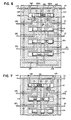
- FIGS. 8 and 9 illustrate a modification of the cyclic feed line spool valve lubricant dispenser assembly of this invention, the modification being that shown at 16 in FIG. 1.
- the modification involves the use of a shunt valve block 200 controlling lubricant flow to the control valve block 102 of the assembly of FIG. 4.
- inlet-outlet lines 140 and 141 are plugged in the control valve block 102 and lines 142(a) and 143(a) (shown plugged in FIG. 4) are opened to the end face 202, the lines 142(a) and 143(a) being extensions, as shown in FIG. 8 of lines 142 and 143.
- the shunt block valve 200 is provided with inlet- outlets 210 and 211 which communicate to shunt valve bore 215 which receives shunt spool 216.
- the spool 216 is provided with intermediate undercuts 217 and 218 and is biased by spring 219 towards the right hand end of the bore 215 where a pilot extension 220 of the shunt is in operative association with actuator 222.
- Actuator 222 may be a solenoid actuator or may be otherwise constructed and is effective to, when activated, bias spool 216 to the left against the spring 219.
- FIG. 11 illustrates yet another embodiment of this invention which functions similarly to the embodiment of FIG. 4 but which utilizes one way check valves between the inlet-outlet ports.
- the cyclic feed line lubricant dispenser assembly is provided with inlet-outlet ports 300 and 301 which communicate respectively with lines 305 and 307 which in turn are provided with one way check valves 302 and 304 before communicating with the central feed line 306.
- the block is provided with three spool valve bores 308, 312 and 316 which contain a control spool 310 and dispensing spools 314 and 318.
- the control spool 310 is provided with undercuts 320 and 322 and the spool is free to move between ends 332 and 338 of bore 308.
- Dispensing spool valve 314 is provided with undercuts 324 and 326 and is free to move between ends 334 and 340 of bore 312.
- spool 318 is provided with undercuts 328 and 330 and is free to move between ends 336 and 342 of bore 316.
- Feed line 306 communicates with the central reaches of both bore 312 and 316.
- Line 346 communicates with the last of the bores, in this instance, bore 316, and with inlet-outlet line 301 while line 344 communicates with inlet-outlet line 300 and with the last of the bores, 316.
- Dispensing lines D1 ⁇ D4 are provided for dispensing lubricants to lubricant demanding areas.
- the lubricant will be provided to the end 332 of the control valve bore 308 and simultaneously pass check valve 302 to feed line 306.
- Check valve 304 will prevent lubricant from passing direct to line 307. Presence of lubricant under pressure in the end 332 of bore 308 will bias control spool 310 to the right, thus communicating line 350 to the end 332. Any lubricant in the end 338 of bore 308 will, during translation of the spool 310 to the right be ported out line 307. The presence of high pressure lubricant in line 350 will bias the spool 314 to the right.
- feed line 306 Upon translation of spool 318 to the right, feed line 306 will be in communication with line 346 via undercut 328. Line 346 is in communication with inlet-outlet 301 and thus lubricant will now flow through the valve assembly.
- High pressure lubricant will now be provided via line 307 and pass check valve 304 to the feed line 306 and to the end 338 of bore 308. This will cause spool 310 to be translated to the left thus opening line 352 to the end of bore 312 to provide high pressure lubricant from line 307 to the end chamber 340 to translate spool 314 to the left.
- Line 344 being in communication with the inlet-outlet 300 will provide for flow of lubricant through the assembly from inlet-outlet 301 via line 307 past check valve 304 through feed line 306 through undercut 330 to line 344, and through line 344 to inlet-outlet 300.
- FIG. 10 illustrates a variation on the device of FIG. 4. Similar functioning bores, lines and passageways of FIG. 10 are numbered the same as in FIG. 4 except that the numbers are given a 400 series in place of the 100 series numbers of FIG. 4.
- control spools 431, 432 are modified from the prior design so that each spool has three undercuts and three lands.
- the undercuts are provided at 480, in the end chamber, at 481, intermediate lands 483 and 484, and at 482, intermediate lands 484 and the inside end land 485.
- the spool may be recessed at 490 for receipt of the spring 435.
- the control bore 429 is provided with different line entrances. In place of line 130a of FIG. 4, which was opened by movement of the control spool 131, bore 429 has two lines, 470 and 430a. Line 470 is positioned opposite line 450 so that movement of control spool 431 to the right from that shown in FIG.
- this embodiment also provides a feed line cyclic spool valve lubricant dispenser assembly with the ability to function in a reversing loop.
- this invention provides a cyclic spool valve lubricant dispenser assembly of the feed line type modified by a control valve to be used in reversing loop feeder systems with the spool valve assembly shifting each of its dispensing valves once during each reversal of pressure in the lubricant loop.
Landscapes
- Engineering & Computer Science (AREA)
- General Engineering & Computer Science (AREA)
- Mechanical Engineering (AREA)
- Multiple-Way Valves (AREA)
Claims (7)
Applications Claiming Priority (2)
| Application Number | Priority Date | Filing Date | Title |
|---|---|---|---|
| US602133 | 1984-04-19 | ||
| US06/602,133 US4572331A (en) | 1984-04-19 | 1984-04-19 | Reversible feeder system |
Publications (3)
| Publication Number | Publication Date |
|---|---|
| EP0159633A2 EP0159633A2 (de) | 1985-10-30 |
| EP0159633A3 EP0159633A3 (en) | 1987-01-14 |
| EP0159633B1 true EP0159633B1 (de) | 1990-01-24 |
Family
ID=24410099
Family Applications (1)
| Application Number | Title | Priority Date | Filing Date |
|---|---|---|---|
| EP85104461A Expired - Lifetime EP0159633B1 (de) | 1984-04-19 | 1985-04-12 | Umkehrbares Zuführungssystem |
Country Status (4)
| Country | Link |
|---|---|
| US (1) | US4572331A (de) |
| EP (1) | EP0159633B1 (de) |
| CA (1) | CA1237992A (de) |
| DE (1) | DE3575597D1 (de) |
Families Citing this family (29)
| Publication number | Priority date | Publication date | Assignee | Title |
|---|---|---|---|---|
| US5199528A (en) * | 1991-12-05 | 1993-04-06 | Atlas Copco Aktiebolag | Flow controller |
| US5565770A (en) * | 1994-07-15 | 1996-10-15 | Lubriquip, Inc. | Linear position sensor including a first open housing having a reciprocal, biased magnet holder and magnet and removable second housing having a hall sensor |
| DE19514177A1 (de) * | 1995-04-15 | 1996-10-17 | Baier & Koeppel | Verfahren zur Zu- und Umschaltung einer Reihe von Progressivverteilern, sowie Einrichtung zur Durchführung des Verfahrens |
| US5730174A (en) * | 1996-07-01 | 1998-03-24 | Lubriquip, Inc. | Solenoid valve cartridge for lubrication divider valves |
| US6260664B1 (en) * | 1998-11-24 | 2001-07-17 | R.R. Donnelley & Sons Company | Press lubrication system modification |
| CN1161549C (zh) * | 1999-04-13 | 2004-08-11 | 马上光治 | 压力流体自动切换装置 |
| US8555927B2 (en) | 2003-04-01 | 2013-10-15 | Coltec Industrial Products Llc | Fluid divider block suitable for use at high pressures |
| US7096889B1 (en) * | 2003-04-01 | 2006-08-29 | Curtis Roys | Fluid divider block suitable for use at high pressures |
| GB2403298A (en) * | 2003-06-23 | 2004-12-29 | David Mark Needham | A fluid flow meter using spool valves |
| RU2281430C2 (ru) * | 2004-03-11 | 2006-08-10 | Открытое Акционерное Общество "Николаевский Завод Смазочного И Фильтрующего Оборудования" | Дозирующе-распределительное смазывающее устройство |
| USD615619S1 (en) | 2004-04-01 | 2010-05-11 | Curtis Roys | Fluid divider block |
| RU2273792C2 (ru) * | 2004-06-01 | 2006-04-10 | Открытое акционерное общество "АВТОВАЗ" | Нагнетательное устройство с программируемой подачей смазочного материала и централизованным контролем |
| DE202005010673U1 (de) * | 2005-07-07 | 2005-09-22 | Lincoln Gmbh & Co. Kg | Notschmiereinheit für Einleitungsschmiereinrichtungen |
| US20070029140A1 (en) * | 2005-08-05 | 2007-02-08 | Lubriquip, Inc. | Series progressive lubricant metering device |
| DE202009002951U1 (de) * | 2009-02-14 | 2009-04-30 | Lincoln Gmbh | Schmierstoffverteiler |
| US9388941B2 (en) | 2011-10-17 | 2016-07-12 | Lincoln Industrial Corporation | Compact lubricant injector and injector system |
| DE102011086179B4 (de) * | 2011-11-11 | 2014-11-06 | Lincoln Gmbh | Progressivverteilergrundkörper sowie Progressivverteiler mit derartigem Progressivverteilergrundkörper |
| DE102012013709B3 (de) * | 2012-07-11 | 2014-01-02 | Sms Meer Gmbh | Schmiervorrichtung zur Versorgung einesWerkzeugs mit Schmiermittel |
| US9151444B2 (en) * | 2012-10-01 | 2015-10-06 | FD Johnson Company | Dual-series feeder lubrication system |
| ITMI20121885A1 (it) * | 2012-11-06 | 2014-05-07 | Dropsa Spa | Dosatore modulare progressivo adattabile |
| ITMI20121884A1 (it) * | 2012-11-06 | 2014-05-07 | Dropsa Spa | Dosatore modulare progressivo |
| CN103343869A (zh) * | 2013-07-22 | 2013-10-09 | 上海大众汽车有限公司 | 加油工位自动监控系统 |
| US9470363B2 (en) | 2014-02-03 | 2016-10-18 | Curtis Roys | Mono-material divider block assembly |
| US9581294B2 (en) | 2014-02-07 | 2017-02-28 | Curtis Roys | Replaceable sleeves used in distribution blocks |
| US10788132B2 (en) | 2017-05-10 | 2020-09-29 | Graco Minnesota Inc. | Hydraulic changeover valve |
| US11435028B2 (en) | 2019-04-30 | 2022-09-06 | Lincoln Industrial Corporation | Lubricant injector |
| US11231055B1 (en) * | 2019-06-05 | 2022-01-25 | Facebook Technologies, Llc | Apparatus and methods for fluidic amplification |
| DE102020126055A1 (de) * | 2020-10-06 | 2022-04-07 | Skf Lubrication Systems Germany Gmbh | Progressivverteiler |
| DE102021104272A1 (de) * | 2021-02-23 | 2022-08-25 | Skf Lubrication Systems Germany Gmbh | Progressivverteiler |
Family Cites Families (12)
| Publication number | Priority date | Publication date | Assignee | Title |
|---|---|---|---|---|
| US2269928A (en) * | 1939-06-12 | 1942-01-13 | Carl E Dirkes | Lubricating system |
| FR973635A (fr) * | 1941-10-22 | 1951-02-13 | Consortium Francais D Automobi | Distributeur-doseur pour systèmes de graissage central |
| US2794518A (en) * | 1953-09-21 | 1957-06-04 | Trabon Engineering Corp | Lubricating system and sequence valve therefor |
| US3107681A (en) * | 1962-03-27 | 1963-10-22 | Westinghouse Air Brake Co | Double check valve |
| US3298460A (en) * | 1964-08-18 | 1967-01-17 | Mccord Corp | Divisional lubricant feeder |
| US3414085A (en) * | 1965-02-03 | 1968-12-03 | Daikin Ind Ltd | Centralized lubricating system |
| GB1197009A (en) * | 1967-09-27 | 1970-07-01 | Mccord Corp | Lubricating System |
| US3866627A (en) * | 1972-06-21 | 1975-02-18 | Caterpillar Tractor Co | Dual check valve arrangement |
| DE2438726C2 (de) * | 1974-08-12 | 1983-12-15 | Société d'Applications des Machines Motrices, 92130 Issy les Moulineaux | Druck-Flüssigkeitsverteiler |
| US4105094A (en) * | 1976-12-14 | 1978-08-08 | Houdaille Industries, Inc. | Single line lubricant reversing feeder |
| US4312425A (en) * | 1978-09-11 | 1982-01-26 | Houdaille Industries, Inc. | Cyclic lubricant distributor valve |
| JPS5675396A (en) * | 1979-11-22 | 1981-06-22 | Komatsu Mfg Co Ltd | Safety device for crane |
-
1984
- 1984-04-19 US US06/602,133 patent/US4572331A/en not_active Expired - Fee Related
-
1985
- 1985-04-12 EP EP85104461A patent/EP0159633B1/de not_active Expired - Lifetime
- 1985-04-12 DE DE8585104461T patent/DE3575597D1/de not_active Expired - Lifetime
- 1985-04-18 CA CA000479436A patent/CA1237992A/en not_active Expired
Also Published As
| Publication number | Publication date |
|---|---|
| CA1237992A (en) | 1988-06-14 |
| DE3575597D1 (de) | 1990-03-01 |
| US4572331A (en) | 1986-02-25 |
| EP0159633A3 (en) | 1987-01-14 |
| EP0159633A2 (de) | 1985-10-30 |
Similar Documents
| Publication | Publication Date | Title |
|---|---|---|
| EP0159633B1 (de) | Umkehrbares Zuführungssystem | |
| US5791142A (en) | Hydraulic control valve system with split pressure compensator | |
| US4580678A (en) | Reciprocating floor conveyor system | |
| KR100298068B1 (ko) | 압력보상유압제어밸브장치 | |
| KR19990037212A (ko) | 비-셔틀식 압력 보상기를 갖는 유압 제어밸브시스템 | |
| WO1996036825A1 (en) | A hydraulic directional-control valve | |
| US4352375A (en) | Control valves | |
| US5273069A (en) | Operation valve with pressure compensation valve | |
| US3476214A (en) | Divisional lubricant feeder with bypass means | |
| US6098403A (en) | Hydraulic control valve system with pressure compensator | |
| US4471805A (en) | Control valve | |
| GB2257495A (en) | A slide valve | |
| US2007156A (en) | Lubricating system | |
| US4252147A (en) | Rotary connection for passage of hydraulic oil | |
| US4276896A (en) | Flow control valve assembly with integrated torque and flow divider control | |
| US3414085A (en) | Centralized lubricating system | |
| US4609330A (en) | Modular unloading sequencing switching valve assembly for hydraulic system | |
| US2954051A (en) | Control valve for multiple valve banks | |
| ZA200304176B (en) | Lubrication device for the supply of several lubrication points. | |
| US4570672A (en) | Hydraulic control valve with independently operable bypass valve | |
| US2856023A (en) | Progressive metering valve and fluid pressure system utilizing same | |
| US4832082A (en) | Hydraulic pilot operated directional control valve | |
| US2794518A (en) | Lubricating system and sequence valve therefor | |
| US4538504A (en) | Fail-safe servovalve system | |
| US2684732A (en) | Reverser for lubricating systems |
Legal Events
| Date | Code | Title | Description |
|---|---|---|---|
| PUAI | Public reference made under article 153(3) epc to a published international application that has entered the european phase |
Free format text: ORIGINAL CODE: 0009012 |
|
| AK | Designated contracting states |
Designated state(s): BE DE FR GB IT |
|
| PUAL | Search report despatched |
Free format text: ORIGINAL CODE: 0009013 |
|
| AK | Designated contracting states |
Kind code of ref document: A3 Designated state(s): BE DE FR GB IT |
|
| 17P | Request for examination filed |
Effective date: 19870701 |
|
| 17Q | First examination report despatched |
Effective date: 19880413 |
|
| RAP3 | Party data changed (applicant data changed or rights of an application transferred) |
Owner name: LUBRIQUIP INC. |
|
| GRAA | (expected) grant |
Free format text: ORIGINAL CODE: 0009210 |
|
| AK | Designated contracting states |
Kind code of ref document: B1 Designated state(s): BE DE FR GB IT |
|
| ET | Fr: translation filed | ||
| REF | Corresponds to: |
Ref document number: 3575597 Country of ref document: DE Date of ref document: 19900301 |
|
| ITF | It: translation for a ep patent filed | ||
| PLBE | No opposition filed within time limit |
Free format text: ORIGINAL CODE: 0009261 |
|
| STAA | Information on the status of an ep patent application or granted ep patent |
Free format text: STATUS: NO OPPOSITION FILED WITHIN TIME LIMIT |
|
| 26N | No opposition filed | ||
| ITTA | It: last paid annual fee | ||
| PGFP | Annual fee paid to national office [announced via postgrant information from national office to epo] |
Ref country code: FR Payment date: 19930304 Year of fee payment: 9 |
|
| PGFP | Annual fee paid to national office [announced via postgrant information from national office to epo] |
Ref country code: BE Payment date: 19930318 Year of fee payment: 9 |
|
| PGFP | Annual fee paid to national office [announced via postgrant information from national office to epo] |
Ref country code: DE Payment date: 19930320 Year of fee payment: 9 |
|
| PGFP | Annual fee paid to national office [announced via postgrant information from national office to epo] |
Ref country code: GB Payment date: 19930322 Year of fee payment: 9 |
|
| PG25 | Lapsed in a contracting state [announced via postgrant information from national office to epo] |
Ref country code: GB Effective date: 19940412 |
|
| PG25 | Lapsed in a contracting state [announced via postgrant information from national office to epo] |
Ref country code: BE Effective date: 19940430 |
|
| BERE | Be: lapsed |
Owner name: LUBRIQUIP INC. Effective date: 19940430 |
|
| GBPC | Gb: european patent ceased through non-payment of renewal fee |
Effective date: 19940412 |
|
| PG25 | Lapsed in a contracting state [announced via postgrant information from national office to epo] |
Ref country code: FR Effective date: 19941229 |
|
| PG25 | Lapsed in a contracting state [announced via postgrant information from national office to epo] |
Ref country code: DE Effective date: 19950103 |
|
| REG | Reference to a national code |
Ref country code: FR Ref legal event code: ST |